
Abstract
Load rating of contactor switches is an important issue for diverse industrial power applications requiring varied connections. This paper presents a simple procedure to evaluate the current-carrying capabilities of contactor switches under overload cyclic stress. An experimental setup is proposed to measure test current, contact voltage drop, and temperature at the contacts and cable connectors. Results are presented for ON–OFF controlled commutated current at 500% and 1000% overload of a contactor in the ON position. The attained results and the criteria for contactors selection in power applications are given.
I. Introduction
Current-carrying capabilities of contactor switches are defined by design and manufacturing in accordance with international recognized standards such as UL, CE, and so on. There are two principal heating sources in the contactor contact. The former and more important is the electrical current flow, and the latter is the cable contacts to the contactor terminals. Electrical contacts have predefined allowed excess temperatures depending on temperature and type of environment in which contacting is performed. 1
Many applications that require power switching are implemented using electronic devices such as silicon-controlled rectifiers (SCRs), Triacs, insulated-gate bipolar transistor (IGBTs), and so on. However, applications for contactor relays are still commonly found in household appliances, automotives, telecommunications, and aerospace. Hence, electromechanical relays still play an important role. 1 Automated test equipments (ATEs) are electronic systems where switches and relays are the best solution because of simplicity in operation and electrical insulation properties. In case of ATE applications, where sensitive measurements are required, electromechanical relays offer practically zero closed impedance (<50 mΩ) and almost infinite open impedance (>100 GΩ), while providing high bandwidth characteristics (>100 MHz). 2
Moreover, switches and electromechanical relays still play an important role in industry. During their exploitation, electric contacts are subjected to high current levels, and numerous ON–OFF cycles. Contacts often fail due to several factors, for instance, material transfer and pitting, arc erosion, corrosion, sticking and welding, and even plastic deformation. The assessment of contact reliability is a complex task due to the lack of information on all the parameters affecting contacts under the multiplicity of operating conditions. 1 In power applications, contacts are subjected to the limits of nominal current design values, and under current overload conditions, the use of computer aided engineering (CAE) software is required, and is complemented by experimental work to evaluate contact dissipation performance. CAE methods are used to more accurately estimate the thermal interface resistance, which is very important in any thermal analysis program. 3
The main function of the contactor is either to transmit an electrical signal or to distribute electric power. For power connectors, heating can lead to an increase in contact resistance and sometimes contact surface melting and the eventual damage of the connector. 4 Temperature rise due to sliding friction and electrical current may be the major source of sliding electrical contact deterioration. 5
In this paper, results of thermal characteristics of riveted contactor type electric contacts are presented with potential applications in ATE systems that handle overload currents for short periods of time (less than 1 s ON and 10 s OFF), with emphasis on dependencies of contact temperatures under load conditions. Results are obtained for 500% and 1000% overload current for contacts in the ON position. Contacts are tested to determine the thermal time response of heat dissipation in one contact (one pole) within switching contactor, subjected to constant nominal current for 1 h to reach steady state. A simplified model is presented to compare the calculated dependencies of contact temperatures with the experimental work with overload current values. The obtained results are discussed on the basis of appropriate maximum current overload for the reliable operating work cycle.
II. Experimental Setup
The experimental setup comprises a 1.5 kVA power transformer, a variac, two opto-isolated relay control ports, one voltage sensor, a current sensor, three thermocouple sensors, a real-time data acquisition and control system, and the contactor under test. Figure 1 shows details of the test setup.
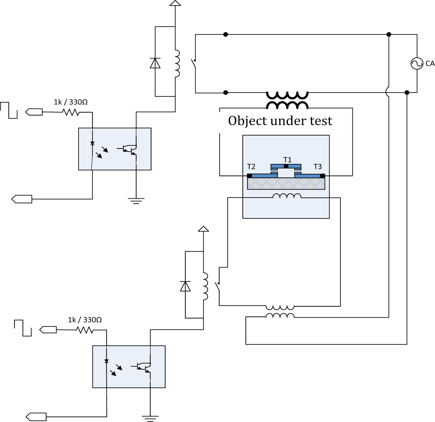
Test setup for contactor
The power transformer is used to supply a test current of up to 400 A from the 120 V (AC) from the mains, the variac is adjusted to set the test current, the opto-isolated relay control ports are used to trigger the contactor and the current flow from the power transformer to the contactor contacts, the voltage sensor is used to measure the voltage drop on the contactor contacts, the current sensor is used to measure and monitor the test current, the three thermocouple sensors are used to measure the temperature at the terminals of the contactor and the temperature rise at the main contacts, and the real-time data acquisition and control system is used to perform the test procedure and timing, and to measure and record values of the temperature at the contacts, and the current and test voltage. The device under test is a contactor series 3100 from Tyco.
III. Test Procedure
The test consist of performing a temperature rise test at rated current for 1 h on a contactor in the ON position; in this paper, the device to be tested is a 30 A commercial contactor. Subsequently, it is made to perform a temperature rise test for overload currents at 150 A and 300 A. The tests are executed using work cycles of 1 s–10 and 0.5–10 s respectively. Figure 2 shows the work cycles of 0.5–10 s for a temperature rise test at 300 A, and Figure 3 presents the thermocouple location on a contractor for a temperature rise test. Figure 4 shows the actual waveform for the 300 A test.
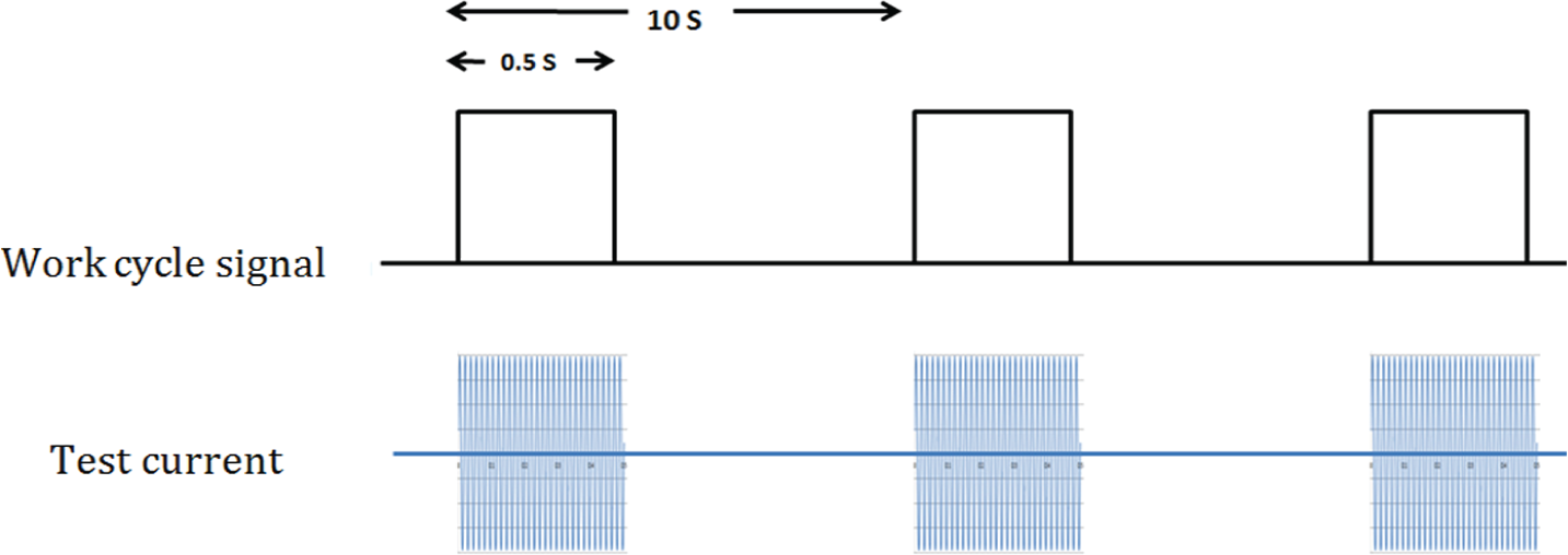
Work cycles of 0.5–10 s for a temperature rise test at 300 A
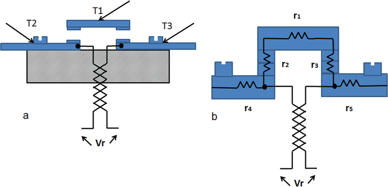
(a) Thermocouple locations on a contactor for a temperature rise test. T1 is the temperature at the main contact, and T2 and T3 are the temperatures at the electrical connection terminals of the contactor. (b) Dissipation resistances associated with a contactor r1 is the resistance of the contact bridge that holds the upper contacts, r2 and r3 are the contact resistances, r4 and r5 are the contact cable connection resistances. Vr is the voltage sensor to measure the voltage drop across the contactor contacts
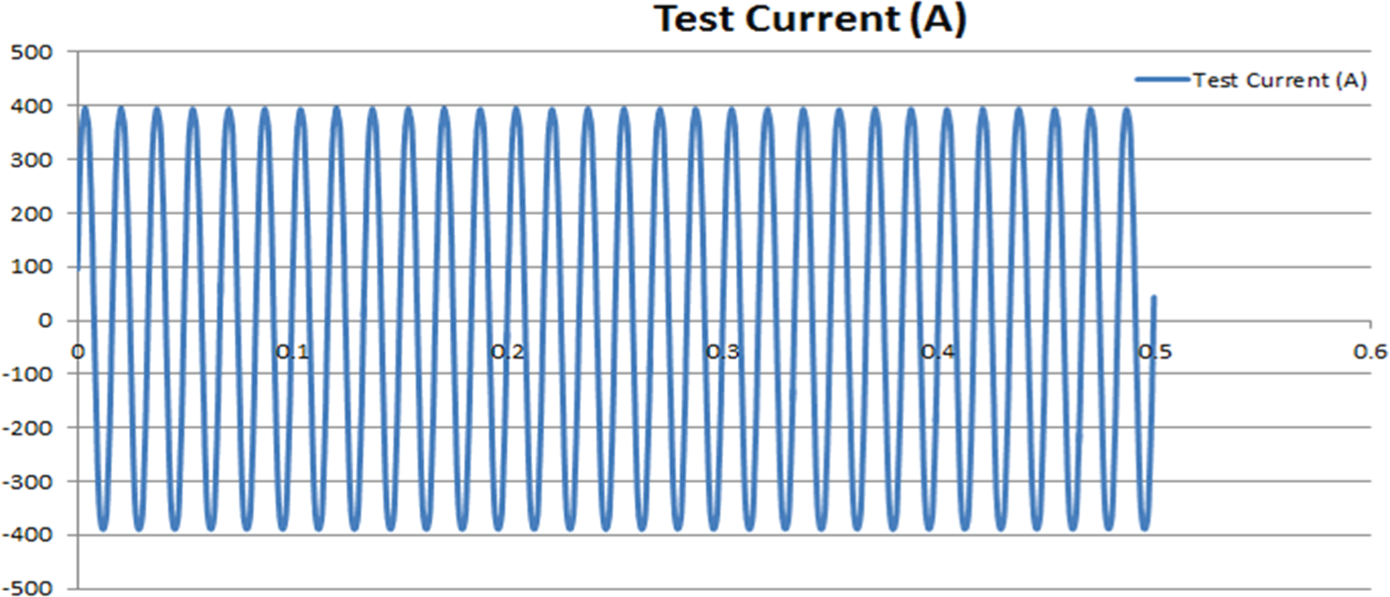
Test current at 300 A RMS, and a 0.5 s ON (30 cycles of 60 Hz)
Measurements of voltage drop across the contactor contacts resistances are recorded during the test to evaluate the contact dissipation temperature dependence. Figure 3 presents the resistances associated with a contactor where r1 is the resistance of the contact bridge that holds the upper contacts, r2 and r3 are the contacts resistances, and r4 and r5 are the contact cable connection resistances. Vr is the voltage sensor to measure the voltage drop across the contactor contacts.
IV. Results and Discussion
The test of the contactor at 30 A rated current for 1 h gave a temperature rise of 72 °C; the temperature response is given in Figure 5 . It shows the temperature rise for the main contacts and terminals. The temperature difference between the main contacts and terminals is about 7 °C, and the hot point is the contact itself, and the cable terminals act as a heat sink. Fourier’s Law can be used to calculate conductive heat transfer as follows:
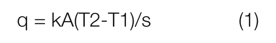
where q is the heat flow in Watts or Joules per second, A is the contact area in m2, k is the thermal conductivity for contacts material made of electrical grade (copper brass), s is the material thickness in m, and T2 − T1 is the temperature difference in Kelvin. In the case of contactors at 30 A rated current, the estimated power dissipation is approximately 15 Watts.
Temperature rise test at 30 A nominal current and 100% work cycle, for a two face contactor
The temperature rise test for 150 A overload current was performed with a work cycle of 1 s ON and 10 s OFF, where the temperature rise was of 65 °C over 25 °C ambient temperature. The temperature rise test for 300 A overload current was performed with a work cycle of 0.5 s ON and 10 s OFF, where the temperature rise was of 117 °C over 25 °C ambient temperature, which exceeds the maximum temperature obtained for the nominal current. Air cooling is required to comply with the temperature limits.
The heating test at 150 and 300 A generates a temperature difference between the main contacts and terminals of about −5 °C, and the hot points are the cable terminals, and the contact is acting as a dissipation heat sink.
The contact resistance and power dissipation can be calculated based on the voltage drop on the contacts, and the test current flowing through the contacts. Equations (2) and (3) can be used to estimate the contact resistance Rc as follows
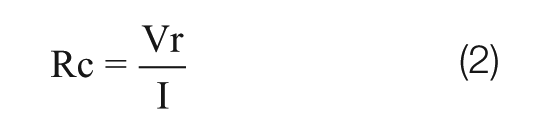
The power dissipation in the contacts can be calculated by

where W is the power in Joules per second (Watts), Vr is the contact voltage drop, and I is the current flowing through the contacts. Figure 6 shows the power dissipation in the contacts as a function of current.
Average power dissipation in the contactor contacts for 30, 75, and 150 A after 1-h test and working cycle of 0.5 s ON and 10 s OFF
The contact resistance has a wide variation, and has a negative temperature coefficient. Contact resistance measurement based on the voltage drop at the contacts is as follows: at nominal current of 30 A test after 1 h of continuous current flow, there is a temperature rise of 58 °C temperature, and a contact resistance of 1.9 mΩ is obtained; at 150 A with a working cycle of 0.5 s ON and 10 s OFF, the temperature rise is 50 °C and the resistance is 0.8 mΩ.
Evaluation of the contact resistance for 75 A and 1 h heat run test gave a maximum resistance of 1.5 mΩ at room temperature. At the end of the test, the resistance was reduced to a minimum of 1.02 mΩ, the resistance variations are shown in Figure 7 .
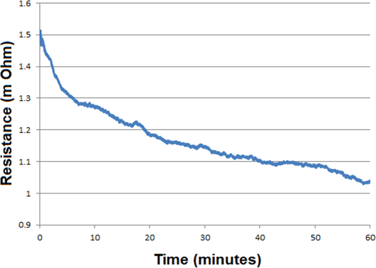
Contact resistance variations for 75 A and 1-h heat run test
Temperature rise test for the contactor depends on the cable connection terminals. The tests performed with heavy copper terminals produced an improvement of 15 °C for a test with a dual contact contactor at 150 A. Figure 8 shows results for the test of 2 contacts with 75 A per contact, and work cycle of 0.5 s ON and 10 s OFF.
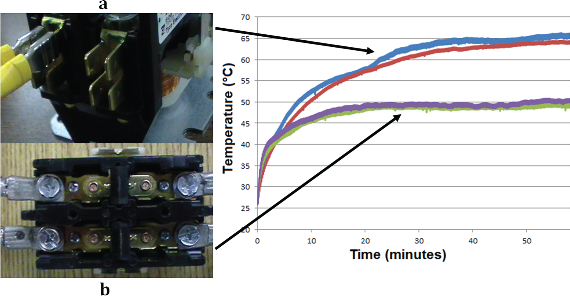
(a) Temperature rise test at 150 A for 2 contacts with 75 A per contact, and work cycle of 0.5 s ON and 10 s OFF. (a) Contactor with original terminals and (b) contactor with heavy terminals
The results of experimental evaluation of the current-carrying capabilities of contactor switches show that low nominal current contactors are applicable for continues small working cycles (1 s ON and 10 s OFF) under overload current upto 500%, and the current capabilities can be improved by modifying the cable terminals and working cycles (0.5 s ON and 10 s OFF) upto 1000%. If different working cycles are required, the criteria for the selection of contactors in power applications should be based on the energy dissipation proportional to the square of the test current and the ON time of the working cycle.
An example for power application for ATE is shown in Figure 9 , where a device under test (DUT) is subjected to a current in accordance with the test voltage and the selected impedance. The use of the contactors tested in this paper allows performing a 300 A durability test when a DUT is a thermomagnetic switch with a duty cycle of 1 s ON and 10 s OFF. An overload test can also be carried out up to 1800 A for a one 60 Hz cycle (16.6 ms). Applications of the diagram presented in Figure 9 can be implemented for single-phase and three-phase testing.
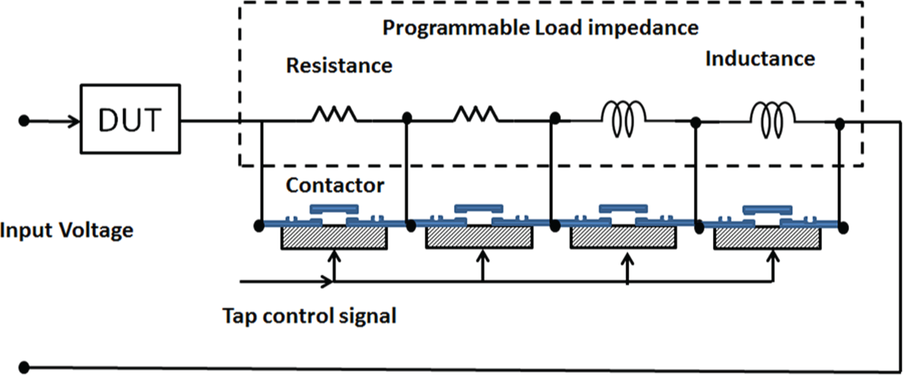
Automated test equipment to evaluate a DUT
V. Conclusion
An experimental setup and simple procedure to evaluate the current-carrying capabilities of contactor switches were presented. The results of experimental evaluation of the current-carrying capabilities of contactor switches were presented. Findings show that in the case of continuous working cycles (1 s ON and 10 s OFF), the overload current can go up to 500%. Current-carrying capabilities can be improved by modifying the cable terminals and working cycles (0.5 s ON and 10 s OFF), and the overload current can go up to 1000%.
The criteria for the selection of contactors in power applications should be based on the energy dissipation being proportional to the square of the test current and the ON time of the working cycle.
Electromechanical relays are a valuable component in power ATE application, and high reliability can be achieved when 500% overload currents are applied for short periods of time (less than 1 s ON and 10 s OFF) without exceeding operating temperature parameters; 1000% overload currents can be handled for very short working cycles (less than 0.5 s ON and 10 s OFF).
Footnotes
Funding
This research received no specific grant from any funding agency in the public, commercial, or not-for-profit sectors.