
Abstract
A large decommissioning cost for the UK nuclear industry is cable and associated infrastructure for Control and Instruments. If future cable installation is reduced or avoided, this would drastically reduce costs.
I. Introduction
The Nuclear Decommissioning Authority owns several site-licence companies in the United Kingdom. Two of them, Magnox Ltd® and Sellafield Sites Ltd®, were both attracted to wireless Control and Instruments (C&I) to help reduce lifetime costs, shorten project timescales, reduce their installed base of equipment, be flexible in project strategies and further improve safety.
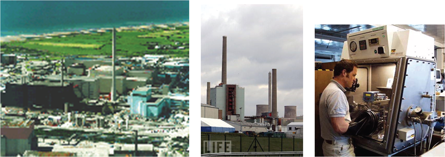
Historically, C&I includes an infrastructure of cables, glanding, trays, trunkings, junction boxes, marshalling panels, power supplies and so on, all with lifetime costs for design, purchase, installation and maintenance. Where C&I is in remote locations (e.g. plants in decommissioning, sewage farm, plant bunds and pits, steam and water services, etc.) or cable access is difficult (stacks, chimneys, furnaces, areas with higher background radiation, ATEX Hazardous Areas (atmosphere explosive (an area with a flammable atmosphere) hazardous areas), etc.), cable infrastructure costs dominate C&I project budgets.
II. Early Alternatives to Wired C&I
Path-finding industries reduced C&I costs by pioneering technologies like multiplexing. C&I wiring is routed to a single multiplexer (Mux); the Mux uses wired telephony or fibre optics to transmit data to a distant location. There, data are de-multiplexed back into their original format (4~20 mA, on/off, etc.). Multiplexing was very useful where the only connection was an existing telephone line, and the dependability and speed of instrument signalling were of low concern.
III. Early “wired” Wireless C&I
Industries later adapted multiplexing to make the telephone line into a radio link. However, this was not true wireless C&I because of the following:
All instruments were still wired and all signals had to be wired to the Mux.
All instruments still had to be powered from a wired supply.
This introduced common points of failure (i.e. the Mux, the radio transmitter and the receiver).
A single Mux limited data capacity (i.e. limited baud rate).
The radio Mux was usually proprietary, that is, specific to one manufacturer. It often used unique hardware and software, spoke only their proprietary protocol and could only be modified, extended or updated by that manufacturer.
IV. True Wireless C&I
The authors assert that a true wireless instrument must have the following attributes:
It should not use cables to output its measurement, status and diagnostics.
It should not use cables to obtain its power (however, in some applications, mains-power may be readily available and could be used).
It should be Commercial Off The Shelf (COTS) technology, readily available from a number of competing suppliers.
It must readily connect with other wireless instruments on a common wireless network without complex information technology (IT) system configuration (i.e. must use a common protocol and give ‘plug & play’ connectivity).
The last point in the bulleted list above was the main problem for true wireless C&I. Early attempts at a common standard for wireless C&I seemed to accomplish little. There were many reasons; no primary standard existed for licence-free wireless (i.e. no standard for frequencies, bandwidths, amplitudes, etc.). It was therefore difficult to develop a standard for a common protocol using technology that itself had few standards.
Despite these problems, several quite capable and effective wireless C&I networks were produced using protocols such as Bluetooth, Wireless Ethernet, ZigBee and so on.
The introduction of IEEE 802.15.4 1 covering licence-free 2.4 GHz bandwidths allowed C&I manufacturers to at least unify around a common method (but not a single protocol) of wireless transmission. Many adopted it as the basis for their wireless networks. However, that standard did not produce a single global protocol. Wireless instruments became available around 2010; typical items are shown in Figure 1 .
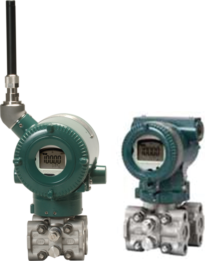
COTS wireless instruments look & behave like their wired equivalents. Note the ‘stubby’ aerial
V. Setting Reasonable Expectations for Modern Wireless C&I
Before Sellafield Ltd and Magnox Ltd selected a wireless protocol, it was important to set reasonable expectations for it. These were
Use the licence-free 2.4 GHz bandwidth
There are concerns about coexistence and interference leading to reliability and latency problems and multiple protocols sharing the same 2.4 GHz bandwidth.
Reasonable expectation – wireless C&I shall not transmit or receive data that are not from a genuine part of its own installation. Data shall not suffer >10 s delay from origin to destination because of bandwidth or latency.
Security
IT security, potential for hacking, jamming, sabotage, loss of service and so on.
Reasonable expectation – wireless C&I shall not transmit or receive data that are not from a genuine part of its installation. Data must be encoded to a standard consistent with the ‘Commercial’ data security classification. All installations shall run ‘in quarantine’ (stand-alone, that is, not connected into wired networks or Distributed Control Systems (DCS) or Programmable Logic Controllers (PLC), that is, no link from a wireless system into a wired system or other network).
Interoperability
An open network (i.e. use C&I from several manufacturers), cost-effective, backwards compatible (i.e. not obsolete in timescales less than those of our major projects).
Reasonable expectation – wireless C&I shall conveniently connect to all approved equipment associated with the protocol being used.
Able to connect to our existing networks (but only at a later date)
Wireless ability to transmit from one remote part of site to another is of great value (see Figure 2 ), but we must be able to do something with the data. Connection to existing networks (i.e. DCS, PLC, emails, intranet, etc.) is already available in COTS. However, early installations shall not connect to existing networks so as to ensure our data security. Connection to site networks is already strictly limited and controlled, so in the future, we must set realistic connectivity targets for wireless to achieve.
Wireless ability to transmit across large areas, from remote locations and to need no cable penetrations is valuable to the UK nuclear industry
Reasonable expectation – wireless C&I shall be capable of conveniently connecting to our site networks at some time in the future.
Our wireless C&I must also be capable of stand-alone operation, for example, able to connect instrument-to-instrument, not requiring IT networks to provide basic functionality.
Signal resilience
Wireless ability to transmit data is reduced by physical obstacles. These include shield walls, pipework, plant steelwork and so on.
Reasonable expectation – a single, stand-alone wireless instrument shall
transmit >200 m in open terrain (fields, car parks, etc.);
transmit >100 m near pipe-bridges, pipe-runs, single-story buildings, etc.;
transmit >50 m inside plant buildings, where plant equipment is dense;
not be expected to transmit through shield walls nor massive constructions.
Where longer distances are required, ‘Gateways’ (repeater stations) or instruments with built-in repeaters shall be used. These allow wireless installations to cover several square kilometres and to transmit data from dozens of separate instruments.
Climate, environment and interference
Wireless C&I must function in ambient conditions at Sellafield and Magnox sites.
Reasonable expectation – wireless C&I shall perform reliably at
−15°C to +33°C;
0%–95% relative humidity;
in ambient conditions defined by rating IP65 2 for ‘field’ instruments;
in interference (EMC) encountered at Sellafield, all equipment must be CE marked to ‘rescom-light’ or higher, 10 V/m;
in an ATEX Hazardous Area rated for at least Zone 2;
in the same locations that wired C&I is installed.
Response time
Like any network, wireless data can be delayed or lost for a number of reasons.
Reasonable expectation – wireless C&I shall
automatically reroute data if one particular pathway is unavailable,
monitor for lost data and retransmit it,
not exceed 10 s from origin to destination.
Use in basic plant control systems C&I
Wireless C&I shall be used to indicate, record, alarm and control our plants.
Reasonable expectation – wireless C&I shall
be used to indicate, record, monitor and alarm in Basic Plant applications;
after a suitable proving period, may be used to provide on/off control of Basic Plant, where time responses of between 10 and 20 s are not a problem;
not be used to provide two-term (proportional–integral (PI) control actions) or three-term (proportional–integral–derivative (PID) control actions) control.
Prohibition of use in safety
Our C&I is classified according to its Safety Function.
Reasonable expectation – wireless C&I shall
be classified as Basic Plant;
may be classified as Safety Related Equipment, given suitable diagnostics are used and formal periodic Maintenance Instructions are used;
not be classified as Safety Instrumented Systems (SIS) 3 attracting any Safety Integrity Level (SIL). 4
General Reliability
A wireless C&I installation is (eventually) to give the same general reliability as our wired C&I installations.
Reasonable expectation – a wireless C&I installation shall
be capable of operation 24 h per day, 7 days per week;
need no routine maintenance requiring a whole wireless network to be offline;
be capable of providing defence in depth (e.g. redundancy of pathways, etc.);
where battery powered (the majority), battery life shall be >2 years.
VI. Understanding the Limitations of All Wireless C&I
When we identified our reasonable expectations, it was important to understand there are issues that will always limit our use of wireless C&I. All technologies have limitations, wireless is no exception. These include
A single transmission medium
Wireless C&I transmit and receive data at defined times. Wireless C&I usually remain silent when it is not their turn to transmit. Every wireless instrument connects onto a ‘channel’. There are a limited number of channels within a frequency band (2.4 GHz). The product of the data transmission rate and the number of channels is called the bandwidth. Bandwidth is the bottleneck that determines how many instruments we can have, how often they can transmit and how quickly data reach their destination. Bandwidth is obviously not unlimited and can be exhausted in a wireless network. The network will slow down exponentially as C&I is added or data volumes are increased.
Signal transmission disruption
Wireless signals are adversely affected by distance, physical obstructions (particularly massive structures and earthed metal objects) and occasionally by weather.
Power supply is limited
For C&I to be truly wireless, it should have no wires and thus no wired power supply. Only a few wireless power supplies commercially exist; the two dominant types are batteries and solar/wind. Both impose power limits (a few Watts). Batteries and solar cells have a definite lifespan (less than the life of our plants) and wind power does not work on calm days nor indoors. Some C&I will probably never be suitable for wireless power. Higher power types include electromagnetic flowmeters, control valve actuators, analysers which require a pumped sample and so on. However, where signal cable is unavailable in our plants, mains (230 Vac) power is usually present or conveniently available nearby. COTS C&I exist that are hybrids, consuming mains power but communicating via wireless.
Wireless instrument battery life depends on several factors: ambient temperature, required signal strength and transmissions/hour rate. Instruments transmitting every 5 s usually have battery life > 3 years; transmitting say every 60 s extends this to >5 years.
VII. Benchmarking the Benefits Claimed by Other Users
C&I manufacturers provided testimonials from other users indicating
C&I infrastructure cost reduction of around 40%,
C&I installation time reduction of around 50%,
plant too difficult or costly for wired C&I were now fitted with wireless.
We listed those issues that are of value to us, under the headings Time, Cost and Quality. We set realistic goals that were long term, as we initially thought it unlikely we would reap major benefits on first use (to our delight, we certainly did 5 ).
VIII. Choosing Our Wireless Protocol Carefully
This paper does not recommend one protocol over another; they all have their benefits and challenges. Some are most suitable for high-speed machines, some for chemical plants, and others for vehicles and so on. Many different protocols exist for wireless C&I (fewer for wireless process instruments).
Such a choice would be the subject of a separate paper. However, beyond those issues listed in sections V and VI, we also considered the following:
What wired networks and protocols are we already using?
If experience already exists on wired networks using a certain protocol, we should keep in mind if a wireless version is available. For example there was very little use of Highway Addressable Remote Transmitter (HART) protocol at Sellafield.
What protocol do our major C&I suppliers support?
If our major suppliers already support a protocol and we are unlikely to switch suppliers, there are obvious benefits in considering that.
Are the instruments we regularly use actually available on this protocol? Not all instruments (e.g. flowmeters and pH transmitters) are available on all protocols. We checked carefully as many instruments are planned but few are available COTS.
The advantage of using, wherever possible, just a single protocol were obvious:
Wireless C&I has the same ‘look and feel’ across plants and becomes familiar to both designers and maintenance staff.
Training requirements will be common across the plants.
Common test tools can be used.
Common Maintenance Instructions can be produced.
Common spares holdings, reducing the total number of spares purchased.
Commitment and cost advantages can be leveraged from the C&I suppliers.
Our Reliability Database can be populated by the growing numbers of common wireless C&I, helping substantiate their dependability for future applications.
Sellafield Ltd and Magnox Ltd chose ISA100 Wireless protocol, 6 see Figure 3 .

The ISA100
IX. Sellafield’s Early Trials
A. Before Sellafield started the first design
The C&I architecture was reviewed to confirm it is possible, practical and beneficial to be implemented using wireless. All functional requirements (e.g. performance requirements, communications, locations, etc.) that influence wireless were identified and included within a Design Basis Document. We considered the overall lifecycle costs (particularly training and spares) versus a wired alternative.
B. During the early stages of design
During the early stages, Engineering Flow Diagrams, Process Instruments Data Sheets and so on were produced to confirm the measurements are available in wireless protocol.
The lowest acceptable data transmission rate per instrument and battery life were considered and added to the Process Instrument Data Sheets. We considered the provision of spares, support contracts, technician and operator training, support tools, obsolescence management and configuration control of the wireless C&I throughout their lifecycle.
It was well worth considering the total number of wireless networks required. Once we started using wireless, we suspected the number of networks would grow rapidly. However, it is common sense we should not add a new wireless network where one already exists if that expansion will not adversely affect that existing wireless network.
C. During detail design
We produced a Wireless Network Diagram for each wireless network. This included
the name of the wireless network;
a list of the wireless process instruments by Tag No. and approximate location (building number and approximate location) on that network;
details if the wireless network is allocated for a specific reason (e.g. this network is solely for say “Environmental Equipment” or solely for “Building ### Filter Trials”, etc.).
As in all C&I design, wireless instruments should only be mounted where they obtain the best possible measurement. Measurement location must never be compromised to overcome other issues such as wireless signal strength, transmission distances and so on.
D. Doing a wireless signal survey
The author certainly does recommend some kind of wireless survey is done, particularly for new wireless networks; but what kind of survey?
A detailed wireless signal survey
Tools exist to conduct formal, comprehensive (and often costly) detailed wireless signal surveys. These tools produce complex contour diagrams, spectrum analysis (see Figure 4 ) and other such data. The author questions their ultimate usefulness. On our sites where buildings and plant are both being demolished and erected, commissioned and decommissioned, where temporary structures (scaffolding, cranes, truck parks, portacabins, etc.) come and go, detailed survey data will quickly become out of date.
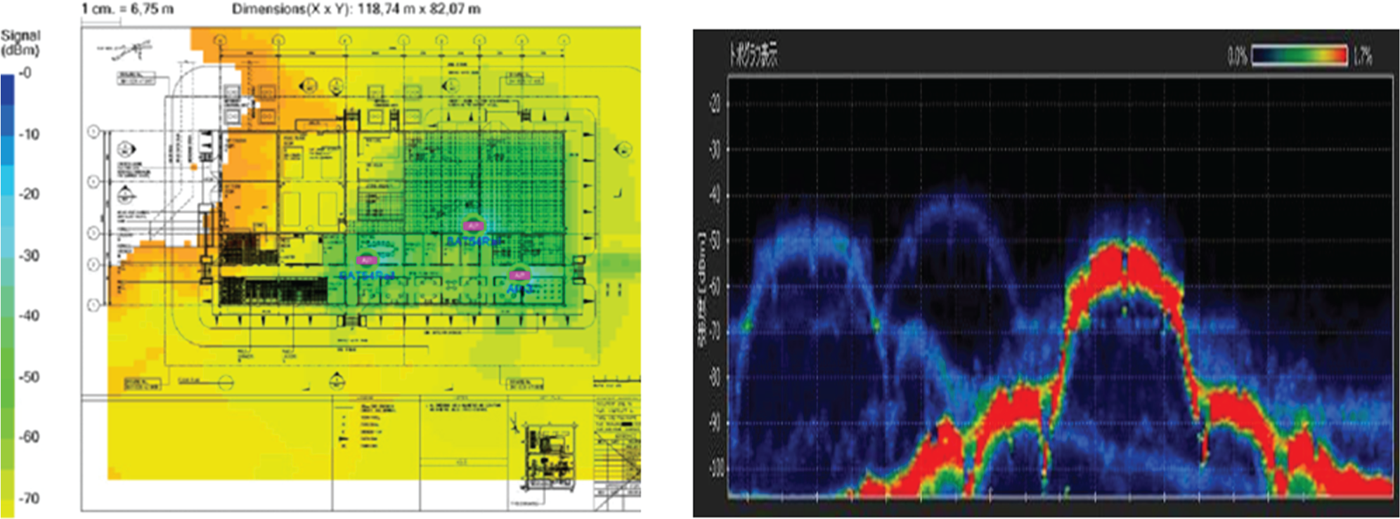
Formal wireless surveys are possible, but before you start, make sure you can actually do something with such detailed data
A simple wireless signal survey
Where a wireless C&I network already exists and the project is to add more wireless instruments to it, it is usually possible to do a just simple wireless signal survey.
Firstly we ‘walked the job’ and classified potential locations versus wireless transmission range and obstacles. Then we took a wireless instrument to the actual location and checked if the appropriate network can communicate with that instrument. Signal strength, update time and so on were checked and confirmed as acceptable. This was done in most of our instrument locations. In an ATEX Hazardous Area and a radiation contaminated area, the instrument was temporarily protected by simply sealing it inside a plastic bag, and later disposing off the bag. We then did an assessment of the effect of adding the total number of wireless instruments onto that wireless network. This included update time, effect on displays and so on.
A mock-up of our wireless network
Tests at the instrument manufacturers were also done, where all our instruments and associated equipment were laid out on the factory floor, set up, run and potential problems injected (e.g. “what happens if the batteries go flat (so we removed the battery) in each instrument?). Software tools supplied with the network configuration software indicated network loading, showed problem areas and so on.
E. Locating our aerials
A major objective of aerial location is to produce a wireless network that has at least two paths leading to the next wireless equipment (called a Mesh network). This provides redundancy in case one wireless instrument becomes inoperable or experiences interference as shown in Figure 5 .
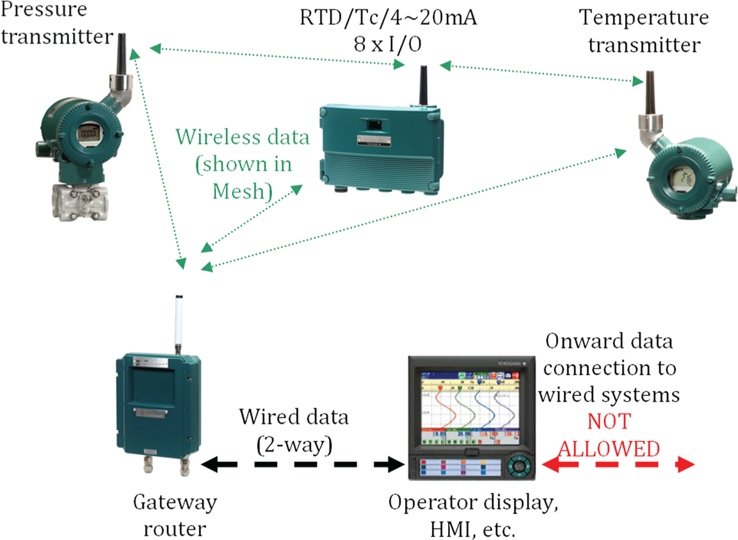
A typical ISA100 Wireless network
Our wireless survey demonstrated the standard ‘stubby’ aerial fitted to wireless instruments was usually adequate. Where it was not, the solution was to site the instrument where wireless reception was better; however, we never compromised the actual measurement by, for example, having long sampling lines and so on.
Where wireless reception remained poor, the solution was to move the stubby aerial. Stubby aerials are supplied ‘remote’, that is, connect to the instrument via a coaxial cable 18 m long. This allowed the instrument to be correctly positioned in the process, while the aerial was also correctly positioned for best reception.
Wireless instruments can also capable be connected to physically larger (about 700 mm long) remote aerials, further improving reception (we did not need these).
An aerial repositioned at height always gave an improvement.
In some of our future applications, it might be essential to mount the wireless process instrument in an area of high radiation. This area may (for radiation shielding purposes) be enclosed behind concrete shield walls or metal partitions. These will affect wireless reception; however, there is no reason to immediately presume they make it impossible. A simple wireless signal survey is essential.
Two solutions may then be possible:
Mount the wireless instruments in-cell and trail their remote aerials through an engineered cell penetration to the out-cell area. This gives the minimum equipment in-cell, but has multiple cell penetrations (cable glands).
Mount the wireless instruments together with their associated Gateway in-cell. Run the Gateway wired output through an engineered penetration to out-cell. This gives the minimum cell penetrations, but all equipment is mounted in-cell.
F. Using the on-board diagnostics
Wireless process instruments feature a considerable number of built-in diagnostic checks. The results are transmitted to the Gateway and then displayed where needed. Early indication of battery usage, data-packet losses and actual signal strength is the most useful for long-term performance monitoring.
G. Buying our spares early
It was well worth buying our spare instruments on the original order. This ensured they came with the same hardware and firmware versions (i.e. are like-for-like) and this simplified Version Control requirements.
X. Results
Wireless C&I gave Sellafield four definite benefits:
Cost – large reduction. Drastically reduced cable costs and costly and specialised cable installation methods (i.e. little or no scaffolds, cherry pickers, installation in ATEX and contaminated areas, at height, installing steel-wire-armour or heavy multicore cables, etc.). Complete elimination of cable junction boxes, tray, trunking, marshalling rooms and so on. ISA100 Wireless protocol instruments are available COTS from a number of competing manufacturers.
Time – significant reduction. There are almost no cables and very little infrastructure to install. Equipment can be ordered early in the design, knowing that its flexibility allows for later design changes.
Quality – small improvements. Wireless process instruments do much more than most wired instruments. All data (i.e. measurements and diagnostics) are always broadcast to everywhere all the time, as standard. Therefore, we asset-manage them more effectively than wired instruments (e.g. only maintain them if they ask for it, interrogate them from the instrument workshop not up a ladder, etc.).
Safety – little improvement, but certainly no degradation. There is no intention to use wireless process instruments in SIS; therefore, this criteria will not apply. However, the reduced cost, ease of installation and flexibility help us to now measure in places that were too difficult or not cost-effective. There are also conventional safety benefits because there is very little installation work required, no need to run cables at height (except rarely to erect an aerial), nor work from scaffolding, nor connection to power supplies and so on.
These benefits are detailed in a later paper. 5
XI. Conclusion
COTS wireless C&I exists. It is easier to use than it first seems. It delivers benefits in cost, time and quality. It has been and will be of great benefit to the UK nuclear industry.
However, like all technology, it will only reap benefits if a strategy is determined before its use.
The decision to use wireless is essentially the same as any other engineering decision, where each option is considered on its individual merits, considering the risks and benefits. The decision is much easier if safety (SIL) applications and IT secure data applications are avoided.
Issues influencing its performance must be fully understood before installation. These include battery life, locations, IT security issues and so on. Choosing the correct protocol is important.
We must also keep a sense of perspective about wired C&I too. It suffers from volt-drop, electromagnetic pick-up, physical damage, corrosion and so on. It is difficult to modify, costly to install and rather inflexible in its use.
Footnotes
Appendix 1
Acknowledgements
The authors thank Simon Marley and Brian Pateman, both Systems Engineers at Sellafield Ltd and Mark Halliwell at Yokogawa UK®, for their work on the first implementation in the UK nuclear industry. All brand names and logos with “®” are the property of their respective owners.
Funding
This research received no specific grant from any funding agency in the public, commercial or not-for-profit sectors.