
Abstract
This paper presents a simple and inexpensive powerless electrical insulated voltage measuring sensor using optical couplers for AC and DC voltage measurement, by harvesting the optical photovoltaic energy from a P–N collector–base junction in an opto-insulator to generate an output voltage proportional to the voltage input. A voltage transducer was built with a low-cost opto-insulator circuit and tested to evaluate the voltage measurement capabilities. The system proved to operate properly for AC power line and DC voltages and switching voltages with a bandwidth of 10 kHz. Applications for the powerless insulated DC–AC voltage sensor are in power electronics, voltage measurement, and control.
I. Introduction
Optically isolated voltage sensors are required and used mainly in power electronic systems with close vicinity to hazardous voltages, and environments with mixed AC, DC, and transient switching voltages. The dominating applications are sensing voltages in electronic power conversion systems, switching power supplies, full-bridge DC/DC converter, DC/AC inverters for wind and photovoltaic (PV) renewable energy systems, and voltage- and current-source pulse-width-modulated (PWM) rectifiers with a power range from a few kilowatts up to several megawatts. 1 Commercial solutions with galvanic insulation and DC and AC measurement capabilities tend to be expensive.
Advanced optically isolated voltage sensors are optical isolation amplifiers based on modulation techniques. An alternative for insulated voltage transducer is a Hall-effect current sensor, with a high resistance in series, using the same technique as current transducers based in closed-loop compensating Hall-effect sensors. Other voltage sensing methods for voltage isolation of analog signals, such as linear opto-insulator for moderate accuracy requirements and piezoelectric-modulated optical fiber Bragg grating sensors for high-voltage applications, have been proposed. 2
Isolated analog-to-digital converters (ADCs) with digital coupling across the isolation barrier are often replacing analog isolation in today’s automation, drives, and energy conversion designs. 3 Linear opto-insulators with linearizing feedback on the isolated side are very linear, but require isolated power supplies at the input and output of the voltage transducer.
This paper presents a voltage sensor based on low-cost optical couplers for bipolar voltage measurement that takes advantage of the electrical insulation and uses energy harvesting of the optical power to generate an output voltage proportional to the voltage input.
A variety of techniques are available for energy scavenging, including solar (light energy) and wind powers, ocean waves, piezoelectricity, thermoelectricity, and physical motions. Conventional two-dimensional P–N diodes can be used for PV energy conversion in a planar geometry. 4 Light energy can be captured via photo sensors, photo diodes, and solar PV panels. 5 Currently, battery is used as a power source in most insulated voltage sensors, with the limitation of battery charge, other applications such as wireless sensor nodes; require periodical replacement of batteries of numerous wireless sensor nodes is impractical. 6
The commercial opto-insulators chosen for the design are used in a push–pull configuration, to handle bipolar voltages and to produce a scaled output voltage with practical characteristics, and do not require any power supply to operate, since part of the light energy from the input light emitting diode (LED) is converted and used by the P–N photo diode collector–base junction inside of the output phototransistor operating at zero bias. 7
PV is a well-understood and mature method of generating electrical power on a large scale and is an environmentally friendly source of micro power. The relation between the optical power and the photo currents is well documented by Piprek. 8 Advanced semiconductors can be designed to allow the transformation of light into current and vice versa. 9
The technology based on direct voltage measurement using opto-insulators has particular applicability to measurements that have to be electrically isolated in environmentally extreme locations without any type of primary power from the digital conversion electronics in the data acquisition system, or microprocessor-based measurement system. Competing alternatives are mapped in Figure 1 , considering the measurement coupling and the galvanic insulation attributes.
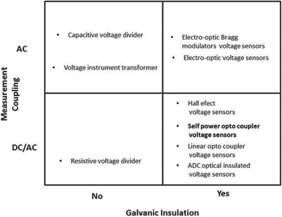
Diagram of technology alternatives for voltage measurement, considering the measurement coupling, and the galvanic insulation attributes
II. Experimental Set-Up and Materials
Two commercial very-low-cost 4N25 opto-couplers are used for the experiments, but the solution is not restricted to this particular component; other components such as 4N28, 4N30, and so on could be used.
The construction of a bipolar voltage transducer connects the input LEDs of two opto-couplers in parallel with inverted polarities, one to handle positive input voltage and the other to handle the negative input voltage; a resistor in series with the LEDs is connected to limit the input current to the LEDs and to scale the input voltage. The positive output voltage is obtained by the PV current circulating from base to collector P–N junction of opto-insulator Opto 1 through resistor R1 for a positive voltage output, and the negative output voltage is obtained by the PV current circulating from base to collector P–N junction of opto-insulator Opto 2 through resistor R2. Figure 2 shows the electronic circuit diagram for the implementation of a bipolar voltage transducer using two opto-insulators.
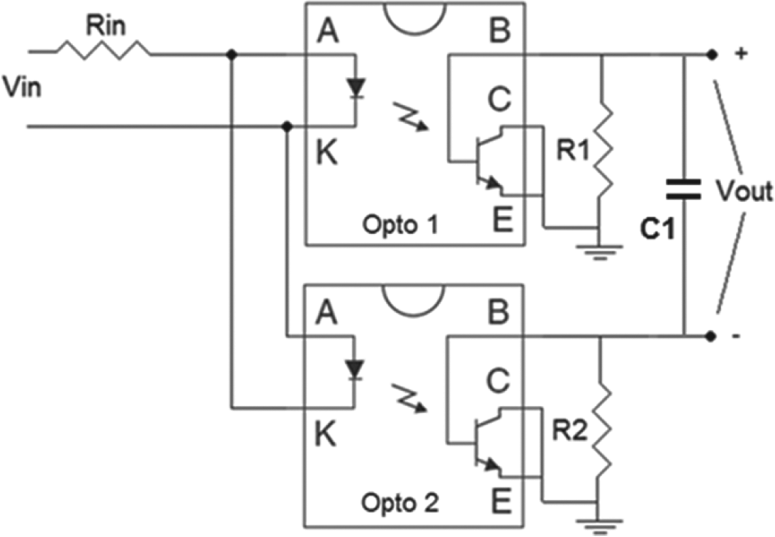
Implementation of a bipolar Voltage transducer using to opto-insulators
A. Circuit implementation
The bipolar voltage transducer was realized using two opto-couplers as shown in Figure 2 . The circuit is designed and built to measure line voltage from the AC mains and power electronics circuits, where a mix of AC and DC signals are encountered. The input resistance is chosen based on the maximum continuous current that the LEDs can handle. Resistors R1 and R2 are chosen to produce the voltage output with a ratio of approximately 5000:1. To monitor 120 VAC, the values are Rin = 4400 Ω, with 10-W power dissipation and R1 and R2 = 1 kΩ; R1 or R2 can be adjusted from 0% to 20% to produce symmetric positive and negative voltages. Capacitor C1 in combination with R1 and R2 is used to limit the frequency response to avoid high frequency noise.
An example of one application of the insulated bipolar voltage transducer is to monitor the voltages in speed control of an induction motor by a dimmer; three points of measurement are illustrated in Figure 3 for the total line voltage, the load voltage at a fan motor, and the voltage developed across the dimmer control.
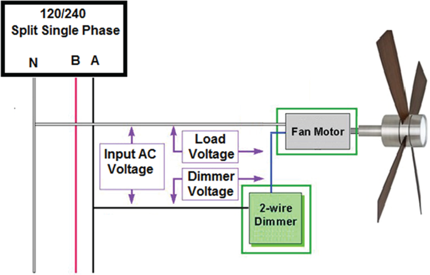
One application of the insulated bipolar voltage transducer using two opto-insulators is to monitor the voltages in speed control of an induction motor by a dimmer
III. Results and Discussion
The results of a simple line voltage measurement test for the bipolar voltage transducer using opto-insulators directly connected to the 120 V grid mains are presented in Figure 4. Figure 5 shows an application example of voltage measurement with a bipolar voltage transducer in the terminals of an AC induction motor with speed control by a Triac dimmer. Figure 6 shows the results for a triangular input voltage from a signal generator to highlight some of the limitations.
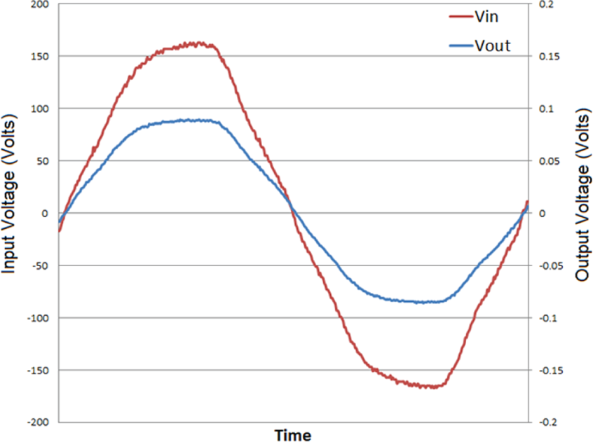
Input and output voltage signals of a bipolar voltage transducer for a 120 VAC mains voltage measurement
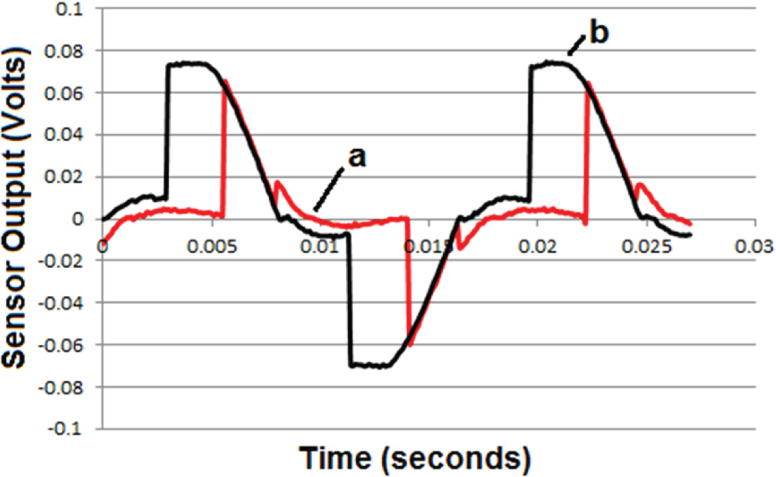
Example of voltage measurement with a bipolar voltage transducer in the terminals of an AC induction motor with speed control by a Triac dimmer: (a) for 1/10 of nominal speed and (b) for ¾ of nominal speed
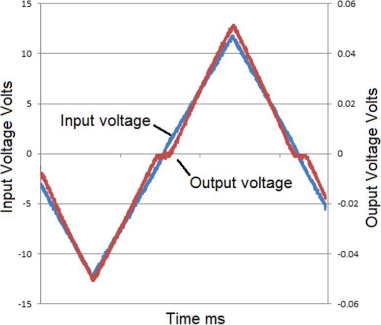
Input and output voltage signals of a bipolar voltage transducer using two opto-insulators for a triangular input voltage from a signal generator
A. Voltage measurement test
The results of the line voltage measurements test were performed at 6 voltage levels from 13 to 139 V. The input and output voltage signals were evaluated to determine the attenuation ratio and attenuation errors for AC voltage measurements. Different input voltage levels exhibit different measurement errors, as shown in Figures 7 and 8. Tests with pure sinusoidal and triangular waves were performed to evaluate linearity errors.
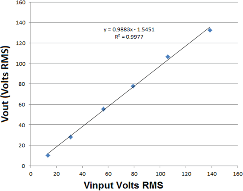
Input versus output voltage for a bipolar voltage transducer using two opto-insulators. The input voltage was a 60-Hz signal from a variable auto-transformer (Variac) connected to the mains
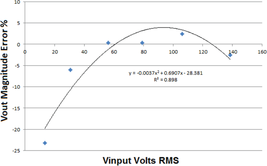
Error estimation results for voltage transducer using opto-insulators
B. Linearity and bandwidth test
In order to evaluate the linearity of the voltage transducer, a test with triangular waves was performed. Results show a non-linearity around the zero crossing of the triangular wave due to the voltage drop required to make the LED conduct current and emit light. The non-linearity errors for a voltage smaller than 15 Vp is around 20% and bigger as the input voltage gets smaller. Data processing could be used to correct for the errors, since the voltage-to-current characteristics for the LED are known and fixed. The transducer was tested to evaluate the bandwidth response using a sinusoidal signal of 15 V pick voltage and a 3 dB bandwidth at 10 kHz was obtained, therefore the reproduction of complex, triangular, and square signals is possible in power electronics applications. Figure 6 shows the reproduction of a triangular wave.
The direct use of the voltage transducer without data processing is from 40 to 140 Vrms, approximately a dynamic range of 3, exhibit errors smaller than 5%. Higher voltages are possible to be measured to cover other line-to-neutral or line-to-line voltages by proportional scaling of the input resistor Rin. The frequency response was tested and is in good agreement with the design; Figure 9 shows frequency response for the bipolar voltage transducer considering R1 and R2 equal to 1 kΩ and C1 equal to 0.001 µF.
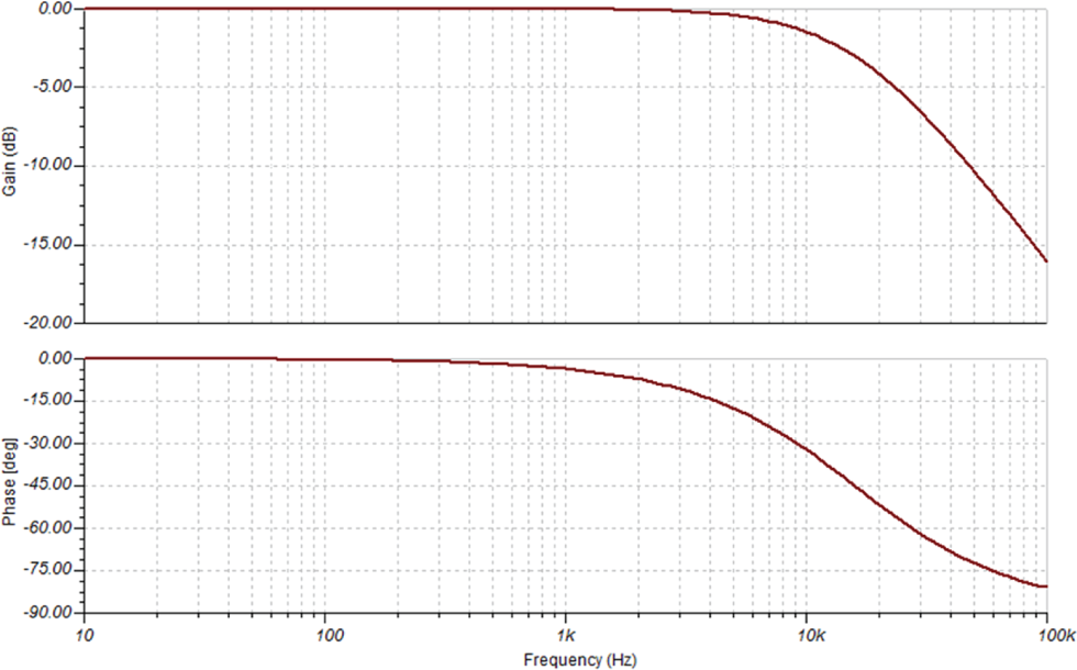
Frequency and phase response for the bipolar voltage transducer
IV. Conclusion
In this work, the presented measurement voltage technique based on PV effect on an opto-insulator proved to be simple, inexpensive, and appropriate for a variety of applications, as in line voltage monitoring and power electronics experimentation. The presented tests show that the linearity error is less than 5% for a line voltage range from 60 to 200 V pick voltage. Voltage magnitude error is less than 5% from 40 to 140 Vrms. The transducer has a bandwidth at 3 dB of 10 kHz approximately and is able to handle mixed AC and DC signals. Therefore, voltage measurement technique through opto-insulators can be a valuable tool for measurement and monitoring of DC and AC voltages in power electronics apparatus where voltage insulation is required.
Footnotes
Funding
This research received no specific grant from any funding agency in the public, commercial, or not-for-profit sectors.