
Abstract

I. Introduction
This article is an overview of the main types of common technology groups utilised for gas analysis applications, together with current working examples of where each technology has been applied. To provide a broad perspective of where the technology can be deployed, I will use a number of application examples to illustrate best practice scenarios across diverse industrial environments such as power generation, metals, cement, steelmaking and biogas. They show how such organisations are tackling legislative compliance challenges, maximising quality control objectives, guaranteeing safety levels and driving operational process efficiencies. While this is not an exhaustive list, it is indicative of the variety of challenges faced by industrial processes. The gas analysis solutions specified to meet such challenges are testament to the flexible, reliable and wide-ranging technology options that are now available.
II. Gas Analysis Technologies
There are three primary group areas of gas analysis technologies that are commonly applied across the process and utilities industries: extractive, in-situ and chromatography. The following observations can be made for each technology:
A. Extractive
Extractive technology solutions are varied. What they have in common is that a sample conditioning system (SCS) is required to extract from the process a sample of the gas to be measured. The SCS ensures that the gas is dry, free from contaminants and is at a constant pressure and temperature. The measurement response time depends on the distance from the process to the analyser and is typically between 30 and 60 s. This means that extractive analysers are ideal for applications in which a fast response time is not critical, such as continuous monitoring and reporting of flue gas emissions.
The following are among the most common types of extractive analysers:
Flame ionisation detection (FID)
FID analysers are used in applications such as the detection of trace hydrocarbons in pure gases or the total measurement of hydrocarbon concentrations for emissions monitoring in waste incineration applications. An example is the Siemens Fidamat 6 (Figure 1).
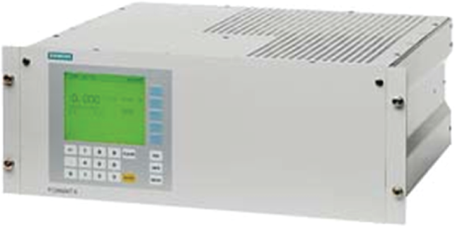
Flame ionisation detection (FID) analyser
These analysers measure the total hydrocarbons in a gas sample, but with different weighting of the hydrocarbon molecules. They work by burning the hydrocarbons in the gas in an oxyhydrogen gas flame. Burning partially ionises the proportion of organically bound hydrocarbons. The released ions are converted into an ionic current by the voltage present between two electrodes and measured by a highly sensitive amplifier. The current measured is proportional to the number of organically bound carbon atoms in the sample gas.
Non-dispersive infrared
Non-dispersive infrared (NDIR) analysers (Figure 2) are used in a wide range of applications, such as emission monitoring, furnace optimisation, biogas analysis and room air monitoring. Gases that can be measured by NDIR analysis include methane, NO, SO2, CO and CO2. An example is the Siemens Ultramat 23 in Figure 2.
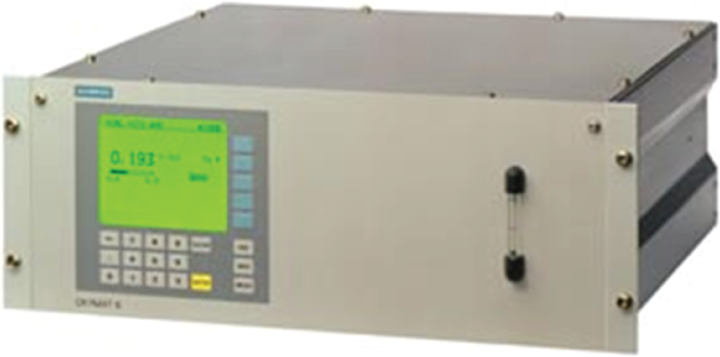
Non-dispersive infrared (NDIR) analyser
The measuring principle of NDIR analysers is based on the molecule-specific absorption of bands of infrared (IR) radiation. A radiation source emits IR radiation, which is then modulated to a specific frequency. A sample of the process gas is introduced, which weakens the intensity of the IR radiation in proportion to the concentration of the measured component. The IR detection chamber can be multilayer, which enables a single analyser to measure more than one component (typically three) in a single-process gas stream. Many NDIR analysers also contain one or two electrochemical cells, which are used to measure reference or secondary gases such as oxygen and H2S. An electrochemical cell works like a fuel cell: the oxygen is converted at the boundary layer between the cathode and electrolyte. An electron emission current flows between the lead anode and cathode via a resistor, where a measurable voltage is present.
UV absorption
Ultraviolet (UV) analysers are used to measure very low concentrations of gases such as NO, NO2, SO2 or H2S. Typical examples include emissions from chemical processes and from gas turbine–based power plants.
The measuring principle of a UV extractive analyser is based on the molecule-specific absorption of gases in the UV wavelength range. Radiation of a wavelength appropriate to the measurement is passed through the sample. The selective absorption, which is proportional to the concentration of the measured component, is determined. An example is the Siemens UV600 (Figure 3).
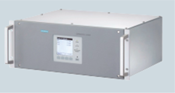
Ultraviolet (UV) absorption analyser
Paramagnetic oxygen
Paramagnetic analysers are used to measure oxygen at process (such as 3%–6% or 0%–100%) and ambient (0%–21%) levels. The main applications are found in industrial gas manufacture (monitoring of ultra-pure gas quality), furnace and boiler flue gas safety measurement and environmental protection.
The paramagnetic measurement principle is unique to oxygen measurement. Two permanent magnets generate an inhomogeneous magnetic field in the measurement cell. Oxygen molecules are drawn into the magnetic field, which results in the displacement of a ‘dumb-bell’-shaped pair of hollow, diamagnetic spheres. This displacement is proportional to the concentration of oxygen. An example of a paramagnetic oxygen analyser is the Siemens Oxymat 6.
Fourier transform infrared (FTIR)
FTIR analysers (Figure 4) are widely used to monitor emissions to air from waste incineration plants, which are required by law to measure a large number of polluting gases, including CO, CO2, HCl, NH3, NO, NO2, N2O and SO2.
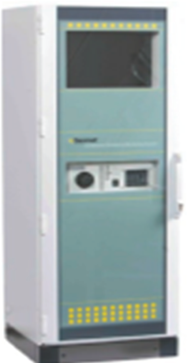
Fourier transform infrared (FTIR) analyser system
The measurement principle of FTIR also uses absorption of IR radiation, but this time, an interferometer is used. The IR spectra of the sample gases are recorded at intervals of a few seconds. The generated interferograms are added together and converted into IR spectra using mathematical Fourier transform routines. The concentrations of the individual components are calculated using multivariate–multicomponent analysis. An example is the Set Gasmet CEMS (Figure 4).
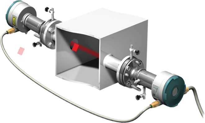
B. In-situ (tuned diode laser)
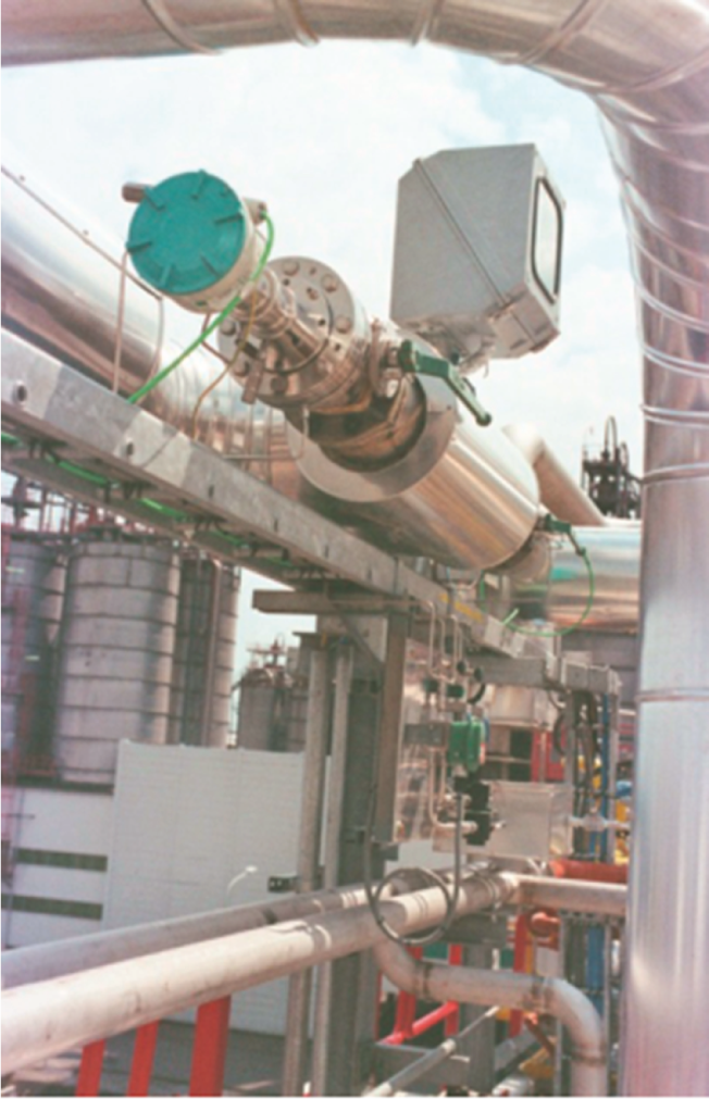
One of the most common in-situ gas analysers is the tuned diode laser (TDL). The biggest difference between an in-situ and an extractive analyser is that the in-situ analyser requires no external sample conditioning. In-situ analysers also have much faster response times (usually around a second), which means that they are typically used as the measured variable for a fast control loop or as a safety measurement that will initiate a process shutdown if unsafe levels of a particular gas (usually oxygen) are measured. The drawback of the in-situ principle is that it is not possible to measure several gases with one device, which is the case with extractive analysers. Hence, extractive and in-situ analysers do not usually compete with each other; they tend to solve different problems.
A TDL laser uses single-line absorption molecular spectroscopy. A diode laser emits a beam of near IR light, which passes through the process gas and is detected by a receiver unit. The wavelength of the laser diode output is tuned to a gas-specific absorption line. The laser continuously scans this line with a very high spectral resolution, and the concentration of the required gas can be measured to a very high degree of accuracy. The most common process gases to be measured in this way are HCl, NH3, O2 and CO. An example of an in-situ TDL is the Siemens LDS 6 (Figure 5).
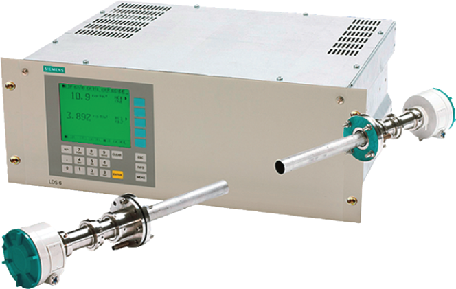
Tuned diode laser (TDL) analyser
C. Gas chromatography
The third category, gas chromatography, is different again. It is still extractive, in that a sample of the gas stream to be analysed must be extracted from the process and conditioned, but the chief benefit of gas chromatography is that it is capable of measuring the concentration of every gas that is present within a stream. This means that the main applications of gas chromatography are to be found in the oil, gas and petrochemical industries. In these industries, gas chromatographs (GCs) can be used to measure the concentrations of the intermediate products, which have a significant effect on the quality of the final products. Before process gas chromatography was widely available, such measurements had to be conducted by taking samples for offline analysis.
The basic principle of gas chromatography is as follows: a sample of the process gas, along with a carrier gas, is injected into a chromatography column, which is a hollow, lined tube. The different gases present in the sample travel at different speeds along the column, so that they separate out. By means of electronic valve switching, each discrete sample can then be measured in a detector. Very sophisticated, multi-stream chromatography is possible, which means that complex hydrocarbon samples can be separated and measured within a single unit. Smaller, less complex analysers can also be mounted in the field, next to the process equipment. Examples of GCs are the Siemens Maxum II (Figure 6) and MicroSAM (Figure 7).
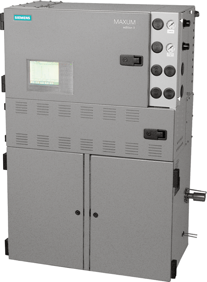
Multi-stream gas chromatograph
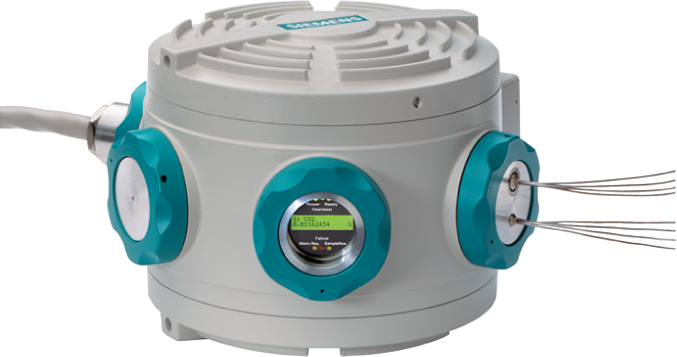
Field gas chromatograph
III. Typical Sample System Design
As mentioned in the ‘Gas Analysis Technologies’ section, extractive analysers require the sample gas to be presented to them in a suitable state, which necessitates the use of a SCS. The main components (Figure 8) of such a system are as follows:
Probe. It is installed within the pipeline or chimney through which the gas to be measured flows. The probe enables a sample of the gas stream to be extracted from the process.
Transport line. It is usually trace-heated to ensure that the sample gas remains at a constant temperature and above the dew point when it reaches the SCS.
Sample conditioning. The number and type of components will vary according to
the process conditions (temperature, pressure, moisture content and
particulate content) and the nature of the gases to be measured. The main
components, however, are Gas cooler – removes any water from the sample gas and
also ensures that the sample is at the appropriate temperature
when it enters the analyser; Pressure reducer – if the process pressure is too high for
the analyser to withstand; Sample pump – ensures a constant flow rate into the
analyser; Particulate trap; Condensate barrier – final trap for any excess
moisture.
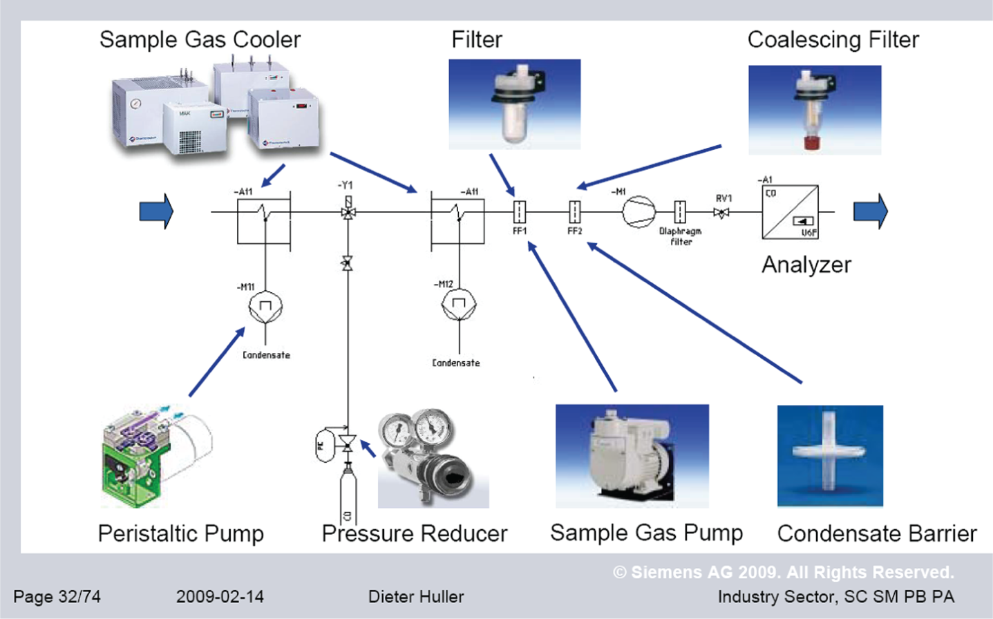
Typical sample conditioning system
IV. Four Golden Rules for Specifying Gas Analysis Technology Solutions
Before going into further detail concerning choice and use of specific technology solutions, it is important to state what, in my opinion, are the golden rules for system specification, whatever the application. This may seem like stating the obvious, but unsuccessful applications of gas analysis technology can always be traced back to the failure to follow one of these rules.
Always select the right analyser for the required measurement.
Design the sampling system correctly, and choose the appropriate components.
If the system is located outdoors, the shelter must be suitable for the prevalent ambient conditions of temperature and humidity.
Ensure a programme of regular maintenance is established and undertaken.
V. Gas Analysis in Action
A. Meeting legislative requirements
Emissions monitoring – Industrial Emissions Directive (Directive 2010/75/EU)
The need to ensure compliance with the demands of the Industrial Emissions Directive places great emphasis upon organisations to ensure process and procedures are in place that can satisfy collection, monitoring and reporting of emissions to air. Ongoing validation and qualification of emissions to air monitoring equipment is a legal requirement, and emission reports must be continually available for inspection by the Environment Agency. The following application for a paper manufacturing operation demonstrates how selected gas analyser technologies were implemented to ensure legislative and reporting success.
A paper manufacturer was driven by a need to acquire low-cost energy, leading to the installation of an energy recovery boiler (ERB), which fell under the jurisdiction of the Waste Incineration Directive (Directive 2000/76/EC). In addition, a combined heat and power (CHP) plant was installed, which required emissions monitoring reporting under the Large Combustion Plant Directive (Directive 2001/80/EC). With two separate emissions monitoring systems in place, a major challenge has been the integration of information streams. The ERB plant uses a combination of NDIR, FID and TDL technology to measure CO, NO, NO2 and N2O (using NDIR), HCl (using TDL) and total hydrocarbons (using FID). The CHP plant uses a single NDIR analyser to measure NO and CO. Report generation has been integrated and automated within the plant’s process control system.
Green energy certification – Renewables Obligation Certificates (ROCs).
In an advanced gasification plant, there is a business need to ensure viability by obtaining a maximum subsidy of ROCs per unit of generated electricity. In order to achieve this, the plant operator must demonstrate that the calorific value (CV) of the synthetic gas (syngas) produced is at least 2 MJ/m3 at the inlet to the generator set (sometimes the generator is driven by a boiler and steam turbine, sometimes by a reciprocating gas engine). In this case, the challenge is in the sample conditioning. Syngas contains both high levels of contaminants and significant quantities of tars, which can liquefy and block the sampling system. The solution is to employ gas chromatography to measure CV and gas composition with traps for tars and contaminants to ensure reliable operation and also to utilise a redundant sampling system to ensure reliable operation.
Natural gas quality and safety – The Office of Gas and Electricity Markets (Ofgem) and health and safety executive (HSE) regulations.
The United Kingdom has a high-pressure natural gas pipeline network, known as the National Transmission System (NTS). When natural gas changes hands along the supply chain, usually when entering the NTS, gas quality and safety-related parameters must be measured. These measurements are specified by Ofgem in the case of quality, and by the HSE in the case of safety. The measurements themselves are complex and include full gas stream composition, hydrocarbon dew point, H2S and total sulphur, oxygen and hydrogen and Wobbe index/CV. Speed of analysis is also an issue. If off-specification gas is detected, the gas in question will have travelled some way down the pipeline before the alarm is raised. The solution therefore is to deploy three GCs at each measurement point. The first GC performs all the quality and safety measurements in a single unit, but there is also a field GC that measures the gas composition with a faster response time. The third GC is a fast-acting unit for measuring H2S and total sulphur, which are vital safety measurements.
B. Quality control
In complex-process plants, quality control is usually a major concern. Gas analysis can play an important role in maintaining quality thresholds. The following applications for the cement, biogas and steelmaking industries illustrate this.
A cement plant has limestone, silica, iron oxide and alumina heated to extreme temperatures in a rotary kiln to formulate cement clinker. This is then ground with gypsum, flue ash and sand to produce finished cement. Continuous analysis of CO, NO and O2 is required to optimise clinker production. With the rotary kiln too hostile an environment for inclusion of a permanent probe in the flue gas stream because of heat levels, dust and aggressive chemicals, one solution is the installation of a self-contained system with a retractable probe, back-flush and NDIR gas analyser. The data produced by the analyser contributes to greater knowledge of the kiln off-gas composition (Figure 9) and more efficient burner control.
Repeatable, accurate and reliable measurement of biogas quality and safety parameters is essential for efficient, safe and profitable operation of biogas-fuelled power generation facilities. In such cases, multi-gas analysis – usually NDIR – can be used for methane (CH4) and CO2 measurements, together with electrochemical analysis of O2 and H2S. Methane and H2S are measured prior to gas cleaning, to gauge the digester performance and again after gas cleaning to ascertain engine performance (Figure 10).
Accurate and repeatable measurement of blast furnace top process gas and basic oxygen steel plant off-gas composition (such as CO, CO2, CH4 and H2) within hostile operating conditions is an essential requirement for quality control in the iron and steel–making industry and is also an aid to the detection of abnormal operating conditions such as water leakage within the furnace. With high temperatures and high levels of dust making reliable gas measurement extremely challenging, analysis solutions must be appropriate. In this case, an extractive NDIR measurement solution is deployed for CO, CO2 and CH4, with thermal conductivity used for H2. Again, the sampling system is a challenge: all items must be ATEX-rated, and it must be possible to back-flush the system’s filters with nitrogen to remove accumulated dust (Figure 11).
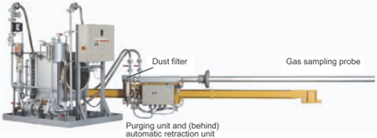
Cement kiln off-gas retractable analyser system
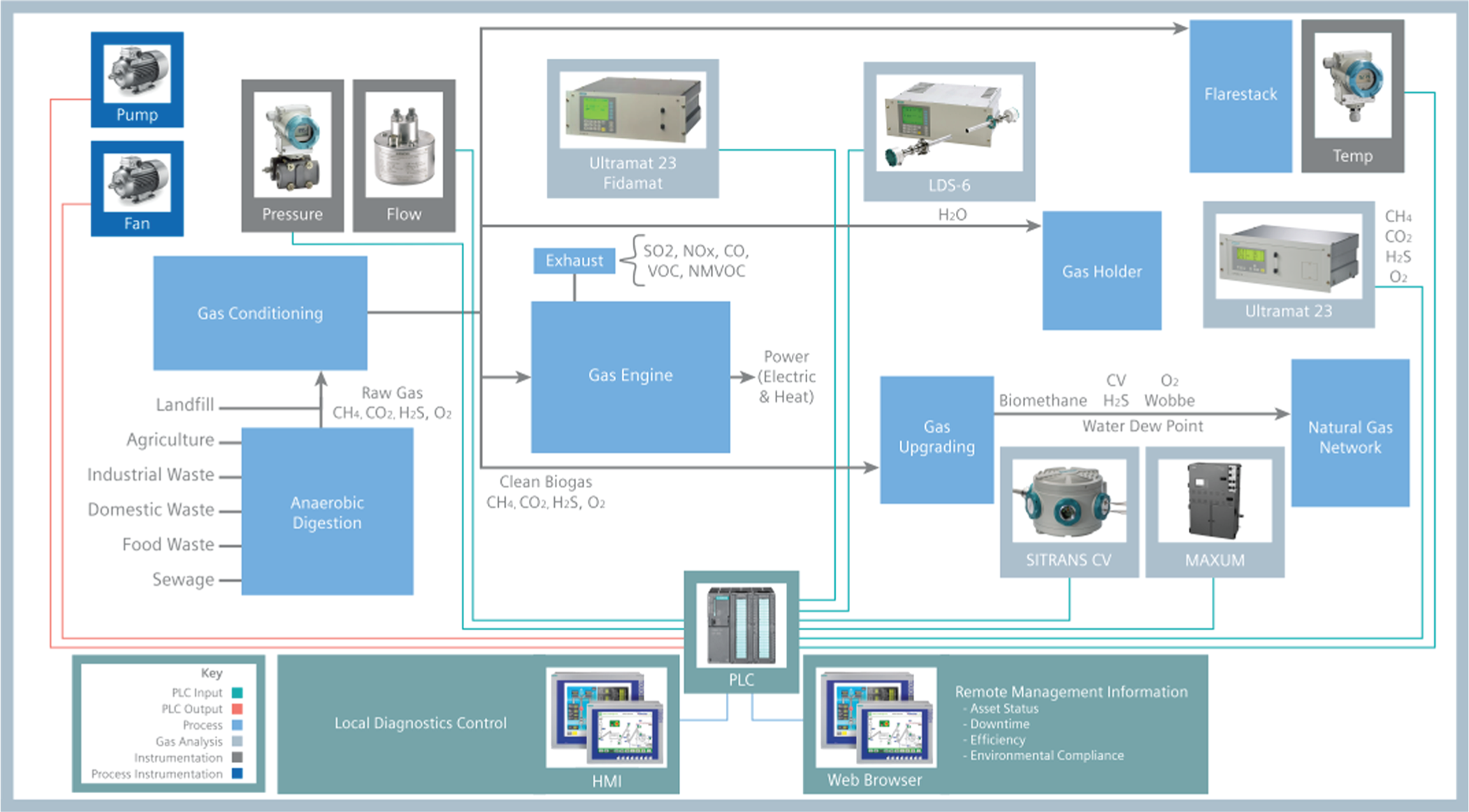
Biogas flow diagram, showing gas analysis points and data management
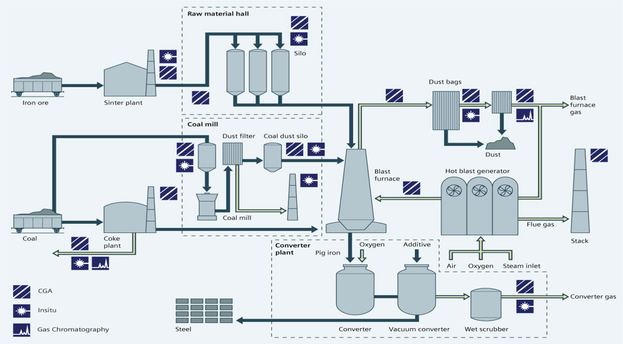
Overview of the steelmaking process, showing points of gas analysis
C. Safety
Safety in potentially dangerous and challenging operational environments is a prerequisite to ensure employees and businesses are protected. The following applications in the powdered metal manufacturing, biogas and power generation sectors illustrate how gas analysis can improve plant safety.
Hard metals manufacturing involves powdering, milling and drying stages. High-risk solvents and potentially harmful chemicals such as cobalt are used – this particular facility is a control of major accident hazards (COMAH) tier 1 production site. Powder is transported from a spray dryer using a nitrogen carrier. Oxygen must be eliminated and measured via a reliable and repeatable gas analyser. There is a business need to minimise the risk of spurious shutdowns without any compromise to safety. The solution is a TDL (Figure 12), which is set to measure 0%–6% oxygen in the gas stream. Its fast-response capability enables the plant safety trip point to be set close to the safety limit without increasing the risk of explosion.
In the biogas industry, oxygen is present in raw biogas, which along with methane and generated heat can potentially cause an explosion. TDL (Figure 13) can be used to provide fast and repeatable measurement of the oxygen present in the biogas. The business case (minimising the risk of spurious trip while maintaining safety) is the same as the previous example.
In coal-fired power stations, dust is removed post-combustion by electrostatic precipitation. Electrostatic filters use the action of force on charged particles in an electric field for dust removal. The dust particles, which are charged through the collection of negative ions, are guided to a receiving electrode in an electric field where they are collected. Electric filters generally pose an explosive hazard by the explosive gas mixture entering the electric field. To prevent such an occurrence, the CO concentration in front of the filter is monitored. In this application, a TDL, tuned to measure carbon monoxide concentration, is used. The fast response of the laser enables the trip point to be set close to the safety limit without increasing the risk of explosion. If CO is detected in unsafe concentrations, operators can deploy a controlled shutdown, thereby ensuring the safety of staff and the operation.
Representation of tuned diode laser in process duct
Field location of tuned diode laser
D. Process efficiency
The operational efficiency of given processes can influence the profitability of the business. The following examples from the power, automotive, glass and steelmaking industries illustrate the contribution effective gas analysis solutions can make to efficiency.
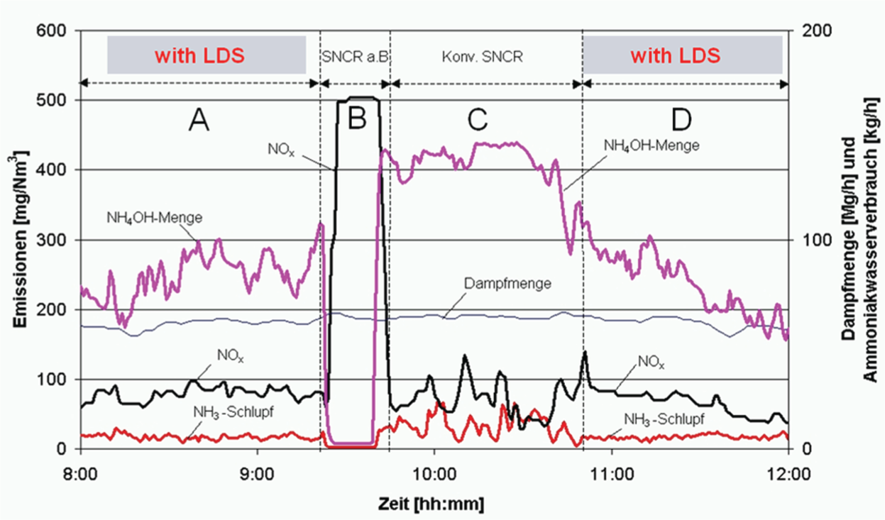
Both the power and automotive sectors are affected by the impact of permissible levels of discharge of oxides of nitrogen (NOx), which are formed through the combustion of fuel in air. Either selective catalytic reduction (SCR) or selective non-catalytic reduction (SNCR) technology is deployed to remove the NOx. These processes use an expensive reagent such as urea or ammonium hydroxide, the by-product in each case being ammonia (NH3) and water. It is feasible for the plant operators to control the amount of reagent used, which is achieved via the measurement of ammonia slip using a TDL. A measured value can be used to control reagent dosing with up to 25% reagent savings proven to be achievable. Figure 14 shows a test carried out on an actual plant and demonstrates the reduction in reagent (NH4OH) usage when closed-loop control is switched on. Some of the text is in German. Menge means ‘mixture’, dampfmenge means ‘humidity’ and schlupf means ‘slip’, as in ‘ammonia slip’ or ‘excess ammonia’.
Furnaces used in the manufacture of glass require exact temperature control. Any variations in CV of the fuel gas – usually natural gas – can lead to the production of inconsistent glass quality. One solution is to deploy in-line measurement of fuel gas composition using a process GC, which can be combined with multi-variable algorithms to optimise furnace temperatures and operating conditions.
With sintering products, such as iron ore fines or water treatment sludge, added to iron ore in a blast furnace to increase production, any incomplete combustion leads to poor productivity. As the sintering products are cooked on a conveyor then crushed prior to loading into the furnace, a TDL (Figure 15) can be used to measure the amounts of CO in the sinter plant chimney. Such readings can be utilised to vary the speed of the sinter strand, thereby ensuring complete combustion. In terms of return on investment, experience from application installations indicate the solution pays for itself within a 6-month period.
The effect of closed-loop control with laser feedback on a de-nitrification process
The use of TDL feedback to optimise sinter production in steelmaking
VI. Conclusion
Gas analysis is an interesting and varied subject. Hopefully, the description of some of the common gas analysis techniques and the case studies of the successful deployment of those techniques have given the reader an insight into the world of process gas analysis.
VII. Glossary
ATEX EU directive describing what equipment can be used in an explosive atmosphere
CH4 Methane
CO Carbon monoxide
CO2 Carbon dioxide
CHP Combined heat and power
COMAH Control of Major Accident Hazards
CV Calorific value (thermal energy content)
ERB Energy recovery boiler
FID Flame ionisation detector
FTIR Fourier transform infrared
GC Gas chromatograph
HCl Hydrochloric acid
HSE Health and Safety Executive
H2S Hydrogen sulphide
IR Infrared
NDIR Non-dispersive infrared
NH3 Ammonia
NH4OH Ammonium hydroxide
NO Nitric oxide
NO2 Nitrogen dioxide
N2O Nitrous oxide
NTS National Transmission System (for natural gas)
O2 Oxygen
ROC Renewables Obligation Certificate
SCS Sample conditioning system
SCR Selective catalytic reduction
SNCR Selective non-catalytic reduction
SO2 Sulphur dioxide
TDL Tuned diode laser
UV Ultraviolet
Wobbe index Ratio of calorific value to relative density (of natural gas)
Footnotes
Funding
This research received no specific grant from any funding agency in the public, commercial, or not-for-profit sectors.