



Abstract
This article considers the requirements for bonding the screens of field cables used in intrinsically safe systems. The possible safety hazard created by potential differences within plant structures is explored, and the recommendation for single-point bonding justified. Figures which illustrate the techniques recommended for commonly occurring installations complete the article
I. Introduction
This article applies only to the screens of field cables. Where screened cables are used for short interconnections in locations where significant voltage differences are not likely to occur, such as within a small cabinet, it is usual to bond the screen at both ends. The screen becomes part of the equipotential plane of this section of the installation.
The only situation where field cable screens have a specified safety function in hazardous areas is the separation of different intrinsically safe circuits in multicores that are not adequately protected from mechanical damage. It is important that the use of a screen does not introduce a hazard. In practice, the use of screens can improve some aspects of safety.
One way a correctly connected screen improves safety is by defining the probable fault path when the cable is damaged. For example, a conductor to screen fault has a defined inductance, whereas a fault to the plant structure is not well defined. Similarly, the capacitance to the screen is well defined and the capacitance to the structure is not. In addition, where a fully floating intrinsically safe circuit is enclosed in a zero potential space by a screen, this mitigates against the circuit drifting to a high voltage with respect to the plant structure. How far this better defined situation increases safety is not quantifiable, but the use of screened cables does decrease the uncertainties.
Screens also reduce further the already low probability of incendive levels of energy being induced into an intrinsically safe circuit. In practice, inducing anything approaching an unacceptable level of energy from an ignition viewpoint (presumably greater than the 1.5 V, 100 mA of simple apparatus) in any instrumentation circuit would produce an operational malfunction. It follows that if a circuit is working then it is also probably not suffering from an unacceptable level of induced energy. However, using screened cables increases the probability of a circuit being both safe and operationally reliable.
There is a general tendency at the present time within electromagnetic compatibility (EMC) circles to recommend bonding electrical systems including screens at all convenient and practical points (e.g. recent Institute of Electrical and Electronics Engineers (IEE) wiring regulations). The assumption made is that the multiple bonding of screens and other equipment ensures that the installation is very well bonded and there is no significant voltage difference between any two points on the structure. In addition, it is assumed that only small currents flow in individual bonds. This is probably true when the bonding points are close together and there is no high-voltage high-power equipment on the site. The current practice is for intrinsically safe circuits to be fully floating or bonded at one point. The multiple bonding of screens would be contrary to this practice. Fully floating screens can possibly create an electrostatic hazard, and consequently, this is not a recommended practice.
When the safety of intrinsically safe circuits is being assessed, the assumption is made that all earthed points are at the same potential interconnected by zero impedance. This is the only practical assumption, but is not easy to completely justify. A well-bonded plant always has significant potential differences across it caused, primarily, by leakage currents from high-voltage electrical equipment. There are other contributory factors such as corrosion potentials and cathodic protection. Higher differential voltages are caused by electrical faults and lightning strikes. Occasionally, instrument cables interconnect areas with different reference potentials, for example, ship to jetty interconnections. These situations and installations using cathodic protection require special consideration. In practice, any long cable whether screened or not can introduce a possible hazard if connected to the structure at two widely separate points by one or more faults. Similarly, where a cable causes a breach in the Faraday cage that usually surrounds a Zone 0, then detailed consideration of the risk needs to be undertaken.
It is to be noted that the majority of petrochemical plants are well-bonded planes because of the interconnected metallic structure. This interconnection is reinforced by the installation of the electrical equipment which has return paths via a conductor and the armour and is also bonded to the plant. Some plants have specific equipotential bonding networks, which further reduce any risk and clarify the installation requirements. Where the soil is conducting, then a further parallel path is provided by the foundations of the plant and the earth mats of power supply and lightning protection systems. However, in many locations, this path is ill-defined and consequently should not be relied upon.
By making a number of assumptions, it is possible to attempt a calculation that helps to put the problem into perspective. Measurements on a number of installations indicate that on a typical well-bonded plant, a voltage difference of 500 mV of predominantly the third harmonic of the mains supply, with 1 V spikes per 100 m can be anticipated. (These measurements were made some years ago, and it is probable that because of the increased use of switch-mode power supplies the bond currents will now contain significant amounts of higher (9th) harmonics.) The screen resistance is typically 2 Ω/100 m, which means a typical fault screen current is 250 mA. The screen inductance is of the order of 1 µH/m, and consequently, the energy stored in the screen is 31 µJ/km. This is less than the 40 µJ associated with inductive circuits in integrated inductive component (IIC) but more than the 17.8 µJ permitted. However, this value combined with the current knowledge of the limited effects of distributed cable parameters suggests that a 1 km screen is not likely to be incendive. However, the assumptions made are not completely defensible, and it is the uncertainty of the consequences that is the reason for avoiding the deliberate bonding of the screen at more than one point. Higher infrequent transients, caused by power system faults or lightning, do briefly create a potentially hazardous level of energy. Consequently, screens, when used in Zone 0, require special consideration.
If a screen or circuit is bonded or capacitively coupled at both ends, then it is desirable to avoid creating a large loop since this increases the risk of unacceptable currents being induced in the circuit. Consequently, the more closely a circuit can be positioned to the plant structure, the lower the probability of significant currents being induced and an incendive spark being created by a break. Presumably, laying cables on well-bonded metallic cable trays is to be recommended. Even when a screen is not bonded at both ends, possible large loops should be avoided so that a hazard is not introduced by faults to the structure.
The inducing of ignition-capable energies on fully isolated wireless aerials by charged raindrops, wind-blown particles, cloud fields or nearby powerful transmitters is a well-recognised phenomenon. Consequently, it does not seem good practice to use exposed instrument cables suspended in space on hazardous plants. If they are securely bonded, there probably is not a significant risk; but anticipating all the possible problems caused by faults is not easy.
II. Preferred Installation Techniques
The ideal screen encloses the circuit (both the outgoing and return leads preferably with a slow twist) in a space that is unaffected by external electromagnetic fields and at the reference potential of the circuit. To minimise the effects of interference, it is usual to bond the screen at one point only, in order to avoid significant circulating currents caused by potential differences in the plant structure. Circulating currents were a smaller problem when it was common practice to use woven screens as they were almost coaxial. Current practice is to use tape screens with a drain wire, and the major part of the circulating current flow through the drain wire with a consequent increase in coupling to the enclosed wires. Tape screens are generally more effective at higher frequencies (i.e. greater than 100 kHz). Screens are usually bonded at one point, normally the 0 V rail of the connected instrumentation. From a safety viewpoint, the screen should be held at or near the plant potential (within 10 V?) and carry only a small current (less than 100 mA?). The 0 V of the connected instrumentation is required to be connected to an electrically quiet point so as to minimise the effect of interference. This connection must also provide a return path for any capacitively coupled current from the mains power supply. These requirements are usually met by connecting to the point where the electrical power system is connected to an earth mat and bonded to the plant equipotential bonding system. Care must be taken to avoid having the screen bonding conductor share any conductor with the return path of the fault or leakage currents derived from the mains supply. These low-frequency currents return to the neutral star point not the earth mat.
Where shunt diode safety barriers are used, then the requirements for bonding the barriers are identical to those of screens. Consequently, it is convenient to use a common return conductor for the barriers, screens and 0 V rail. When isolating interfaces are used, the screens should be bonded in the same way as barriers.
Some users prefer to bond the screen to the structure in the hazardous area and isolate the end in the safe area, especially when using isolator interfaces. This is usually safe on a well-bonded plant but provides an ill-defined path for any fault or leakage currents derived from the mains supply. It also transfers any interference on the plant connecting point to the vicinity of the safe area equipment, and some interaction is inevitable. Bonding the screen in the hazardous area may be acceptable but is not the preferred technique.
There is occasionally concern about the possibility of screens acting as aerials for high frequencies. This is an operational problem since the probability of inducing a power level that could cause ignition by sparking or thermal effect must be low. High radio frequency (RF) power has many dangerous implications and hence should not be permitted to occur. A screen does not form a simple aerial because of its construction and its capacitive coupling to the circuits within it (typically 120 pF/m). How far the performance of a screen as an aerial can be compared with that of a single wire in free space is far from obvious, but the suspicion is that a screen is not an effective aerial. Long cables are usually considered to be the most affected, but the relatively high frequencies in common use in petrochemical plants (2.4 and 5 GHz) have short wavelengths. (The wavelength of a 1 GHz signal is 0.3 m, and it is a quarter wavelength that is usually considered significant. These frequencies may propagate along a cable in a ‘surface wave’ mode that sticks to the cable or is collected at corners or other discontinuities.) The position is further complicated by the fact that almost all field-mounted equipment contains RF decoupling capacitors to the bonding connection of the instrument. These are indirectly connected to the screen via the enclosed circuit and provide some degree of rejection of RF signals.
Occasionally, it is considered necessary to capacitively decouple screens at the isolated end and at points along its length. Currently, the IS standard allows the use of 1 nF high-voltage capacitors for this purpose. The high-voltage requirement is an attempt to ensure the reliability of the capacitors and reduce the possibility of faults to earth. Except on those very rare occasions when terminals complete with decoupling capacitors are provided in the field equipment, mounting these capacitors is difficult. A possible solution is to use capacitors mounted in terminal blocks within a junction box, but this is expensive and inconvenient. In very exceptional circumstances, these terminal boxes could be distributed at points along the cable, but this is very unusual and impractical. It would be interesting to know if such an installation exists on a hazardous plant.
III. Armour
Steel armour has some shielding effect on the contained circuits, but this is most effective at low frequencies. (The use of armour on power cables has the useful attribute of reducing any magnetic field around the cable.) If the armour carries a significant current, then some current may be induced in the contained circuit but the coupling is reduced by the coaxial nature of the armour. Frequently, armoured instrument cable has an internal screen, and this combination is effective from both a mechanical protection and EMC viewpoint.
Where armoured cables are used for intrinsically safe circuits, the armour should be treated in the same way as all other armoured cables, thus avoiding confusion. This means that the armour is bonded to the structure at both ends and any intermediate junction boxes (which must be designed to maintain the continuity of the armour) and becomes part of the bonded structure. The armour may carry significant current, particularly during power fault conditions, but its bonding connections (usually by glands) are secure and incendive sparking should not occur. Where armour enters a Zone 0, particular care should be taken not to import significant voltage differences or current into that location.
The following figures illustrate the connection of screens in frequently occurring situations using the principles outlined above (Figures 1–4).
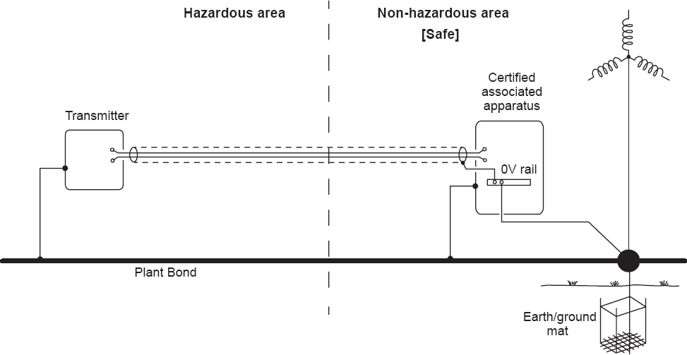
Bonding of screens in a simple system

Bonding of screens in a barrier protected system

Bonding of screens in an isolator protected system

Bonding of screens in a complex system
IV. Conclusion
This article makes recommendations for the bonding of screens in commonly occurring situations. There are occasions when these proposals are not preferred for either operational or safety reasons, and these exceptions can be acceptable if supported by a credible safety analysis. For all installations, it is desirable that the bonding or isolation of the end of screens should be clearly specified in the installation documentation.
Footnotes
Funding
This research received no specific grant from any funding agency in the public, commercial, or not-for-profit sectors.