
Abstract
Emergency lighting facilities are widely installed in public areas such as school, hospital, and station. According the fire regulation in most of countries around the world, such facilities must be installed and checked regularly to ensure their normal working condition. Usually, they are suspended from a high place and distributed widely in the building. Presently, the checking responsibility depends on human operation only, taking at least 30 min for each device. This problem does pose most difficulty to fully meet the required checking rules. Therefore, the proposed scheme develops a portable emergency light checking handset based on wireless transmission/receiving modules integrated with the infrared (IR) ray. The checking command can be transmitted in straight one-way direction, and the checked results can be received at once within 6–10 m. Moreover, the automatic checking mechanism is activated in a prescheduled time. Experimental results reveal that the proposed algorithm can not only control the checking schedule but also read the checked results within the range of 6–10 m instantly. The checking duty relying on the human operation is thus reduced significantly.
I. Introduction
Nowadays, a variety of emergency lights are widely installed in public buildings for safety requirement in case of fire alarm or temporary electricity failure, continuing to supply lighting electricity for a certain period, for example, 30 min. According to the fire regulation in most countries around the world, such devices must be examined and maintained regularly to ensure a good working condition. For example, the battery of emergency light should be checked and discharged every 2 or 3 months. However, even within the same building, these devices are located in different areas. This problem may pose a great difficulty to fully meet the checking criteria if depending on only human operation. Unfortunately, the checking responsibility still relies on human operation today. Therefore, the development of remote automatic checking capability for such emergency lights is an indispensable issue in industry.
This study describes the development of portable wireless handset for emergency light checking. Currently, there is no literature directly related to this study because it is a new idea, not practically produced yet in the market. However, some related techniques are briefly reviewed as follows. This study describes the development of portable wireless handset for emergency light checking. The proposed system using the IR ray integrated with wireless transmission and receiving modules can transmit a control signal to retrieve the checked results using an automation mechanism based on the Microprocessor-based Detector.1–6 Accordingly, the status of the components of the emergency light—charger, battery, and light—can be checked regularly. Besides, a manual operation is designed to implement an instant checking whenever it is necessary. Also, all checked results stored in the Data Recorder can be retrieved any time.6,7–12
This article is organized as follows. “Profile of the System Structure” gives a profile of the proposed system structure. “Demonstration of the Proposed Algorithm” describes the system, both hardware and software, including the operation side and checking side. Particularly, the communication between these two sides is demonstrated and discussed in detail. In “Experimental Results,” the experimental results are presented to confirm that the proposed scheme is capable of online checked results displayed via wireless transmission/receiving modules integrated with the IR ray. Conclusions are given in “Conclusions.”
II. Profile of the System Structure
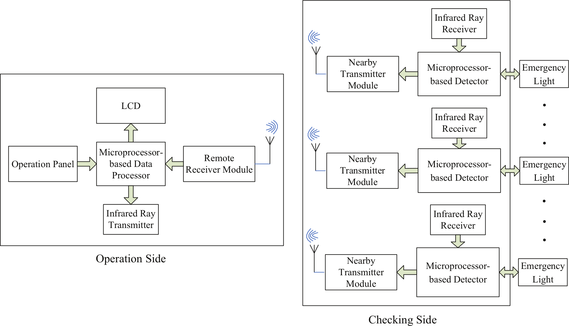
The proposed portable wireless handset for emergency light checking is shown in Figure 1 . It mainly consists of two parts: operation side and checking side. The operation side includes Microprocessor-based Data Processor, Remote Receiver Module, Infrared Ray Transmitter, liquid-crystal display (LCD), and Operation Panel. The checking command is given from the Operation Panel and sent out via Receiver Module. The Infrared Ray Transmitter is used for one-direction signal transmission that can be received only by the assigned Nearby Transmitter Module at the checking side, avoiding any interference occurring from another Transmitter/Receiver Module. The Microprocessor-based Data Processor processes the received results from the checking side and displays it on LCD. On the checking side, Microprocessor-based Detector, Nearby Transmitter Module, and Infrared Ray Receiver are contained. The Infrared Ray Receiver receives the signal from the Infrared Ray Transmitter and thus activates the Nearby Transmitter Module. All checking actions, including the data record, are completed in the Microprocessor-based Detector. More details about the proposed scheme is demonstrated and discussed in “Demonstration of the Proposed Algorithm.”
Depiction of the proposed system
III. Demonstration of the Proposed Algorithm
A. System hardware
Hardware structure of the checking side
The hardware circuit of the proposed system on the checking side is shown in Figure 2 , for more detailed illustration, as follows.

Hardware structure of the checking side
Microprocessor-based Detector: It contains A/D converter (ADC0804), Data Recorder (93C46), Light Detector, and Microprocessor (8051). The battery voltage is converted into a digital signal that is input to 8051. The Light Detector measures the light strength and indicates its status in either sufficient (high) or insufficient (low) level. The Data Recorder is used for recording the checked results. The Microprocessor (8051) is in charge of signal processing, including transmission and receiving of wireless signals.
Nearby Transmitter Module: It transmits the checked results to the operation side.
Infrared Ray Receiver: It receives the command from the Infrared Ray Transmitter of the operation side.
In the checking side, the Light Detector is to check the light strength, shown in Figure 3 . The adjusting resistor (50 kΩ) is used to vary the sensitivity of light detection. According to Equation (1), Q1 will be triggered and turned on whenever the light is on at a good condition, that is, Vcds ≥ 4.11V. The Q2, Q3, and Q4 are thus driven on sequentially. As a result, the resistor 1KΩ will be shortened and results in the output VH = 1. In case of a light malfunction or a bad condition, the output is VH = 1, where Vcds < 3.9V according to Equation (2)
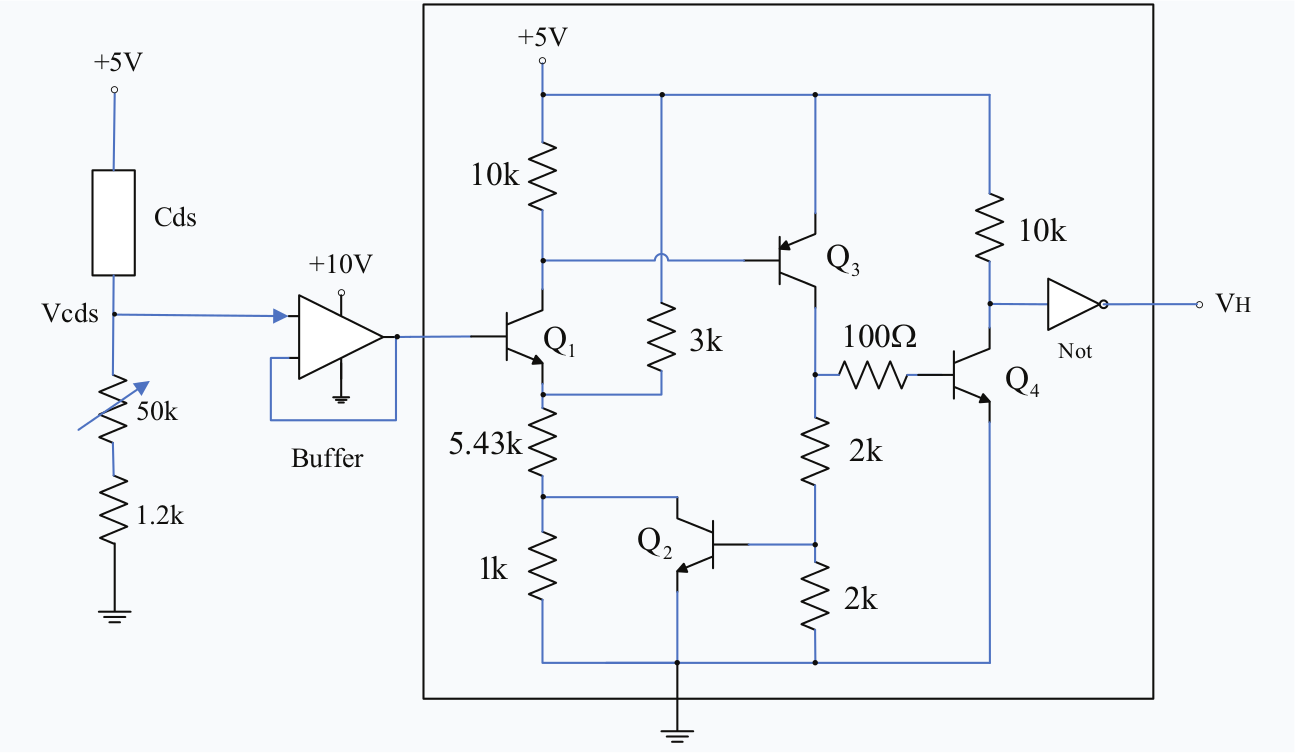
Circuit of the Light Detector


Hardware structure of the operation side
The hardware circuit of the proposed system on the operation side is shown in Figure 4 . More details are discussed in the following.

Hardware structure of the operation side
Operation Panel: (1) SW1: Starts to receive the checked results produced via the automation mechanism or manual operation from the checking side. (2) SW2: Starts manual checking operation. The checking action will begin manually once this switch (SW2) is pressed. (3) SW3: Sequential data reading. (4) SW4: Reads next checked results.
Microprocessor-based Data Processor: Processes the data from the Remote Receiver Module. The checked results are shown on LCD by using SW3 and SW4.
Remote Receiver Module: Receives the checked results from the Transmitter Module of the checking side.
Infrared Ray Transmitter: Transmits control signals of SW1 and SW2 to the checking side.
LCD: Displays the checked results.
B. System software
To carry out the checking performance, the system software is classified into (1) operation programming on the operation side and (2) checking programming on the checking side. More details are discussed in the following.
Operation programming
The operation programming is used to transmit IR signals and retrieve the checked results to/from the checking side. Its programming procedure is briefly described in Figure 5 . More details are discussed in the following.

Flowchart of operation programming
Check if manual operation is requested. If yes, transmit checking IR signal for manual checking operation to the checking side. Then, go to Step (c). Otherwise, go to the next step.
Check if the checked results are requested to be read. If yes, transmit receiving IR signal to receive and display the checked results on LCD from the checking side.
Check if command received is to stop the system. If yes, the system stops. Otherwise, go back to Step (a).
Checking programming
When the Infrared Ray Receiver of the checking side receives the command from the operation side, the Microprocessor-based Detector will soon start the checking performance. The flowchart of emergency light checking is shown in Figure 6 .

Flowchart of emergency light checking
The procedure is briefly described as follows. Note that the charger provides 4.8~5.3 V to charge the battery (3.6 V 700 mAh).
Check if the checking IR signal is received. If yes, go to Step (d). Otherwise, go to the next step.
Check if the receiving IR signal is received. If yes, transmit the checked results to the operation side, and go back to Step (a). Otherwise, go to the next step.
Check if the prescheduled checking period (2 or 3 months) is due. If yes, go to the next step. Otherwise, go back to Step (a).
With the A/D converter, acquire the battery voltage.
Check if the battery voltage is 4.0~4.7 V. If yes, the system of emergency light is confirmed to malfunction. Otherwise, go to the next step.
If the battery voltage is 4.8~5.3 V, it confirms that the condition of charger is OK, battery is bad, and light is unknown. If the battery voltage is less than 3.4 V, it confirms that the condition of charger is bad, battery is unknown, and light is unknown. Then, go to Step (i). If the battery voltage is 3.4~3.9 V, go to the next step.
Check if the light is bright. If yes, go to the next step. Otherwise, it confirms that the condition of charger is OK, battery is unknown, and light is bad. Then, go to Step (i).
Discharge the battery for 30 min.
Check if the light is bright. If yes, it confirms that the condition of charger is OK, battery is OK, and light is OK. Then, go to Step (i). Otherwise, it confirms that the condition of charger is OK, battery is bad, and light is OK. Then, go to Step (i).
Save the checked results to EEPROM (93C46).
Check if command received is to stop the system. If yes, the system stops. Otherwise, go back to Step (a).
Based on Figure 5 , if the system of emergency light is found to malfunction, the charger, battery, and light will not be checked and their status is unknown. More details about the relation between the checking results and representative codes are concluded in Table 1 .
Codes of checking results with status

Note: x means unknown status.
IV. Experimental Results
The circuit boards of operation side and checking side are shown in Figure 7 . The emergency light used for test is shown in Figure 8 .

Circuit board of the proposed system (a) operation circuit and (b) checking circuit

Emergency light with the proposed checking function
A. One-to-one checking
In the experimental tests, first, one operation side to one checking side is used to verify the proposed system. There are up to 10 checked results to be stored in the Data Recorder (93C46). The updated data (checked results) are always saved in the first location. The previous data will be moved to the latter location automatically, such as second, third,…, tenth locations sequentially once new data are received. Besides, the days left for next checking process will come along with the checked results. Figure 9 shows the first checked results and the indication that there are 2 days to go for next automation checking.

The first checked results on LCD
The second to the fourth checked results are shown in Figures 10 – 12 , indicating different situations, respectively.

The second checked results indicating bad battery

The third checked results indicating bad charger

The fourth checked results indicating normal status
The experimental results also reveal that the communication distance using an antenna between the operation side and checking side can be extended up to 10 m. With the IR ray, the command from the operation side can be transmitted to the checking side in a straight one-way direction. As a result, only one checking circuit of emergency light can be operated at the same time. This mechanism can avoid the communication interference occurring from other wireless modules.
B. One-to-multiple checking
The second experiment is to verify the effectiveness of one operation side to multiple checking sides. In this case, one operation set (Num. 3) and two checking sets (Num. 1 and Num. 2) are used and shown in Figure 13 . Figure 14 indicates the location of test devices, where Labels B and C are the checking sides and Label A is the operation side. Note that the distance from A to B and A to C is 6 and 10 m, respectively.

The test devices

The location of test devices
Before the experimental test, the checking side A is arranged working at a normal condition, and the checking side B is simulated working at a bad condition (bad light). Then, use the wireless handset (operation side) to receive the checked results from the checking sides A and B. Figure 15(a) shows the updated data with 2 days left for next checking. Figure 15(b) and (c) indicates that the condition of light is bad, the charger is good, and the battery is unknown. On the checking side B, initially, the manual operation is used to implement the checking process, and it takes 30 min. As a result, after 30 min, the checked results are thus ready for acquisition. Figure 16(a) – (c) reveals that only one day is required to go for next checking to ensure that the working status is normal.

Checked results of checking side A

Checked results of checking side B
V. Conclusion
A portable wireless handset for emergency light checking has been developed and implemented successfully. The proposed handset can send checking commands from the operation side to multiple checking sides within 6–10 m. Based on the IR ray integrated with wireless transmission and receiving modules, the checking command can be transmitted in one-way direction, and the checked results using binary digits (0000~0101) can be received instantly, avoiding an interference from other modules. Also, the automation checking operation can be prescheduled with 2 or 3 months so that the battery life can be prolonged. Alternatively, the manual operation can be activated any time whenever it is necessary. The experimental results confirm that the proposed system can efficiently reduce the load handled by human operation.
Footnotes
Funding
The financial support of this research by the National Science Council, Taiwan, under grant no. NSC 101-2221-E-167 -032 is greatly appreciated.