
Abstract
This article discusses the possibility of using Zenneck surface waves on platforms in order to reduce through-life engineering costs. It is proposed that this can be achieved in two main ways: (1) replace cables with a surface wave channel to increase the flexibility of designs and reduce the cost of repairs and maintenance and (2) use of surface waves for wide area structural health monitoring to reduce service intervals and inspection times.
I. Introduction
As manufacturers take on the whole-life service responsibilities of high-value systems, such as platforms, there is a demand for technologies and design techniques to reduce through-life engineering costs. This can be achieved in several key ways:
Use modular and flexible designs to minimise the cost of changes, such as repairs and upgrades;
Improve reliability, reducing repair and maintenance costs;
Accurately monitor the health of platforms to predict when maintenance is required rather than using conservative time intervals, maximising availability and reducing servicing and inspection costs;
Reduce the number of ‘No Fault Found’, decreasing diagnostics costs.
Wires can be a significant design weakness in any design, creating single-points of failure while also creating an inflexible and complex system to manufacture. Even with these disadvantages, there has been a lack of appetite to move to wireless solutions as these have their own challenges, including reliability and electromagnetic compatibility (EMC).
A possible alternative, providing the flexibility of a wireless solution but the reliability of a wired system are Zenneck surface waves. These propagation modes are similar to a typical home WiFi network with one key difference: the signal is confined to a two-dimensional (2D) surface instead of spreading out into a 3Dsphere. A key advantage of 2D propagation modes is that they provide enhanced power savings compared to traditional wireless solutions as their power is spread over an area rather than a volume.
This article will explore a little of the history of Zenneck surface waves and will then discuss each of the above factors in relation to how the proposed 2D wireless solution could reduce through-life engineering costs.
II. What Are Surface Waves?
Zenneck first identified a mode of electromagnetic waves that propagated over a surface in 1907. 1 These waves were theorised to propagate over surfaces that have particular electric characteristics and decayed exponentially away from the surface.
Various other propagation modes close to a surface were also investigated by various researchers, but some confusion built up over exactly what constituted a surface wave. In Schelkunoff’s 2 1959 article, nine different types of surface waves were identified. In 1960, this lack of clarity was a matter of discussion at the General Assembly of International Union of Radio Science (URSI) held in London. At this meeting, it was concluded that ‘there is no neat definition which would encompass all forms of wave which could glide or be guided along an interface’. 3
In addition, there has been significant confusion between the terms ‘surface waves’ and ‘ground waves’. The cause of this confusion is probably because the Norton surface wave has become one of the more popular types of surface waves to be studied. It is frequently referred to as the ground wave. The Norton surface wave is actually just one component of the ground wave, which can dominate long-range propagation over the Earth and sea. Norton surface waves are in use around the world for surveillance of ship traffic in the form of High Frequency Surface Wave Radar (HFSWR) arrays.
It is, however, important to note the difference between surface waves and ground waves. James Wait, 3 a noted researcher in the area of surface waves, defined them as follows:
A surface wave is one that propagates along an interface between two different media without radiation.
The ground wave includes all components of a radio wave over the earth, specifically the space wave and surface wave but excludes ionospheric and tropospheric waves.
Between the 1960s and now, the Zenneck surface wave had been all but forgotten, with just a few notable articles being published by researchers at the Institute of Moscow. However, it is the opinion of this article’s authors that Zenneck surface waves could provide significant benefit for platform designers. For the remainder of this article, the term ‘surface wave’ will be used to imply ‘Zenneck surface wave’.
III. Reducing Through-Life Engineering Costs
A. Design flexibility
The use of a surface wave–based technology could be applied to any platform; however, for ease of description, we shall consider an unmanned aerial vehicle (UAV). Over the past few years, use of a modular configuration has been proposed. A key advantage of modular designs is that they can be changed to suit the mission requirements obviating the requirement to manufacture and maintain a whole fleet of UAVs, each providing a slightly different capability.
Using modular designs therefore reduces through-life costs; however, one of the key issues with implementing truly flexible modular designs is how to route communications and power. Previously, there were two ways this could be solved:
Use standardised connectors at each joint;
Use wireless communications and distributed power.
Using standardised connectors provides some level of flexibility but still creates limitations. Additionally, connectors are specified for a limited number of connects and disconnects, while also being single-points of failure with this risk increasing with each mating. Both of these issues increase through-life costs.
Wireless solutions provide the ultimate flexibility in modular designs; however, traditional wireless solution generally do not meet TEMPEST or EMC requirements, particularly in relation to interoperability and signature (for military platforms), and they require line-of-sight for reliable communications.
Instead, what if you could confine the wireless signal to within just a few millimetres of the platform? What if non-line-of-sight could simply be part of the link budget? Surface waves will allow you to do just this; they have three unique properties: 4
The E-field decays exponentially away from the surface;
The power of the surface wave attenuates at a rate of 1/r with range as opposed to 1/r2 for traditional wireless systems;
The waves are guided by a meta-material surface (henceforth, referred to as the ‘channel’) and follow the contours of the channel.
A comparison between space waves and surface waves can be seen in Figure 1 . The top figure shows the instantaneous electric field produced by a short electromagnetic pulse from a monopole over a surface wave channel. The bottom diagram shows the field if the surface wave channel is replaced by a metal sheet. The difference in the strength of the field close to the surface is obvious.
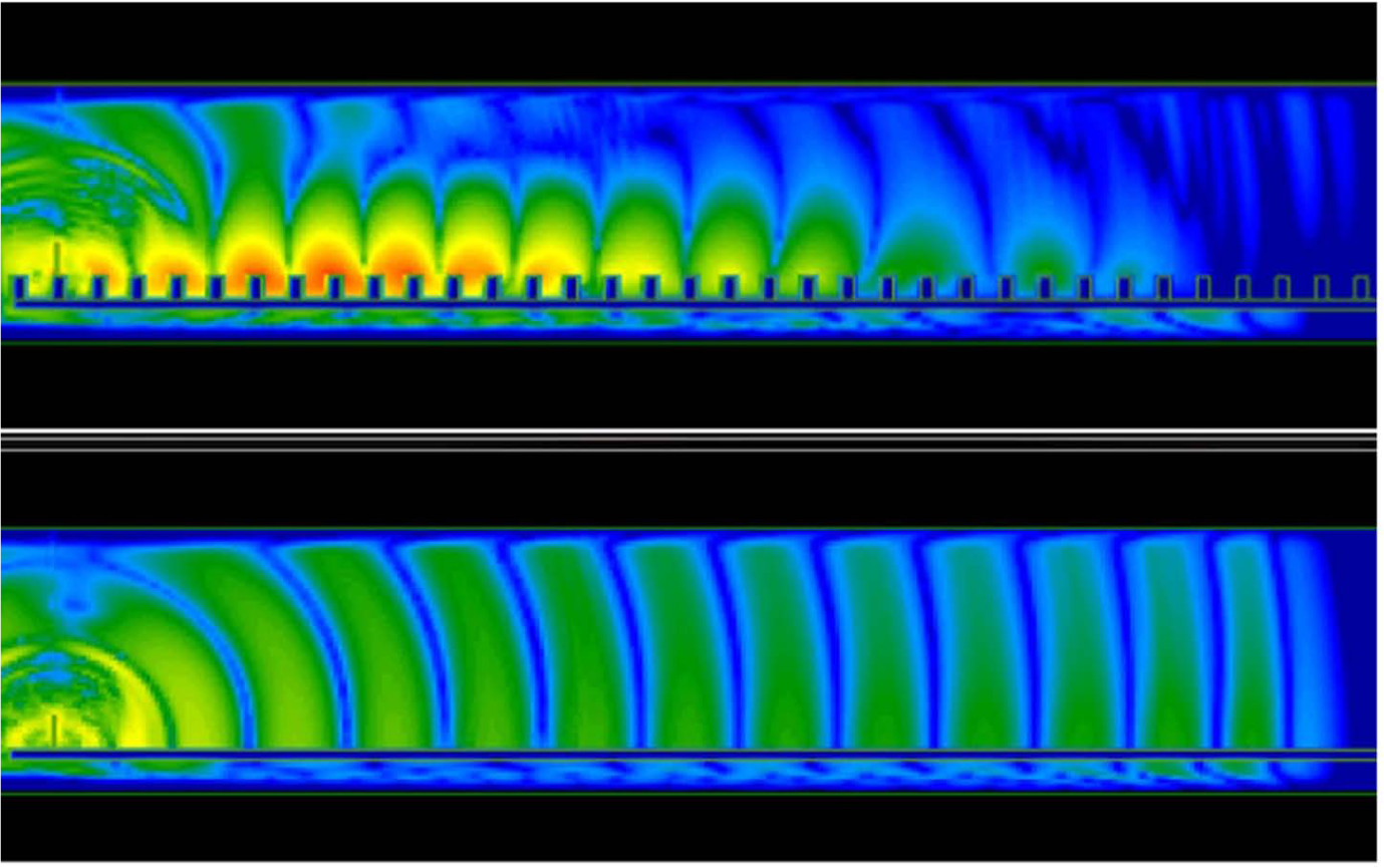
Simulation of the instantaneous electric field produced by a short pulse from a monopole over a surface wave channel (top) and a metal sheet (bottom)
Consider a platform, where the interior is completely covered with the surface wave channel; the structure itself becomes the communications backbone. 5 Sensors and subsystems can be placed anywhere close to or on the surface to become connected to the platforms network. Each of the factors stated above can be compared with traditional wireless technologies and their relative benefits considered.
First, the rapid rate of decay of the E-field away from the channel provides a secure connection that will be less prone to unwanted detection and interception. EMC becomes less problematic as the E-field is highly localised; objects can be placed very close (a few millimetres at 60 GHz) to the channel without interrupting the link. An interferer must be very close to the surface to cause interference, reducing the risk of immunity problems. The low attenuation away from the source in the direction of propagation reduces the power requirement compared with traditional wireless solutions. Finally, the surface following attribute enables wireless communication in challenging environments, particularly when line-of-sight between nodes is not possible. It is in these conditions that traditional wireless technologies struggle to operate.
Therefore, the solution to the ultimate modular and low-cost platform is to integrate the surface wave channel into the structure of the platform. This allows subsystems and sensors to be placed anywhere on or close to the surface providing reliable, wireless communications. Not all platforms will require modular designs, but most platforms will at some point in their life undergo an upgrade or repair.
For example, in civil aviation, airliners need to be able to adjust the percentage of economy and premium seats as demand changes. Unfortunately, each seat is hardwired into the in-flight entertainment systems, which means that there is the requirement for significant re-wiring each time this sort of change is made.
For other platforms, such changes may not be routine, an example being upgrading the bridge of the ship with the latest technology. However, for a wired solution, there will be significant costs associated with re-wiring. Upgrades may also need to occur earlier due to increased data transfer requirements. If these requirements increase beyond a system’s capability, the platform owner either needs to live with a limited system or undertake expensive and highly disruptive network upgrades.
Surface waves can reduce these costs and disruptions. Nodes can be placed anywhere on or close to the surface, allowing subsystems to be easily moved or added. The surface wave channel is capable of transferring large amounts of data; to date, a data transfer rate of 1.5 Gbps has been achieved by streaming a 1080i HD video across a 2000 mm long channel at 60 GHz, the new Industrial, Scientific and Medical (ISM) band, using the equipment shown in Figure 2 . This data rate was limited by the chipset available rather than being an intrinsic upper limit. Using the new WiGig chipsets, due in 2014, and the new IEEE 802.11ad standard, it is anticipated that data rates of 7 Gbps are achievable. If higher data rates are required, a bespoken encoding scheme could be developed, providing the ultimate in flexibility and upgradeability for networks, without the need to make expensive changes at the infrastructure level.
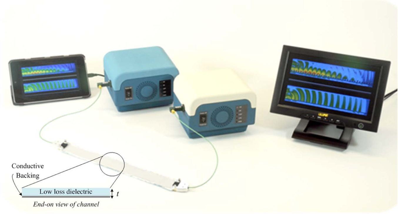
Photograph showing Roke’s ‘gekko’ demonstration kit, whereby t = ~0.5 mm at 60 GHz for the surface wave channel
B. Improving reliability
As already discussed, wires and connectors are not only bulky, heavy and awkward to install, but they are also a single-point of failure. Surface waves provide an alternative, reliable communications network. If damage occurs to the surface wave channel, the surface wave simply ‘jumps’ the damage.
Figure 3 shows a 5-mm gap introduced at 30 GHz (a half-wavelength or λ/2 gap). It can be seen that although some of the surface wave is radiated as a space wave, the majority of it continues to follow the surface wave channel. The size and number of gaps or holes that can be jumped will depend on the transmit power. To put this in context, a relatively large air gap of 2λ (10 mm at 60 GHz) will cause approximately 5 dB of loss; however, it should be noted that this result is for a specific set-up and will vary depending on the surface impedance, frequency and channel width. Although gaps can be introduced unintentionally as a result of damage, intentional gaps can be designed for within the channel and the link budget.
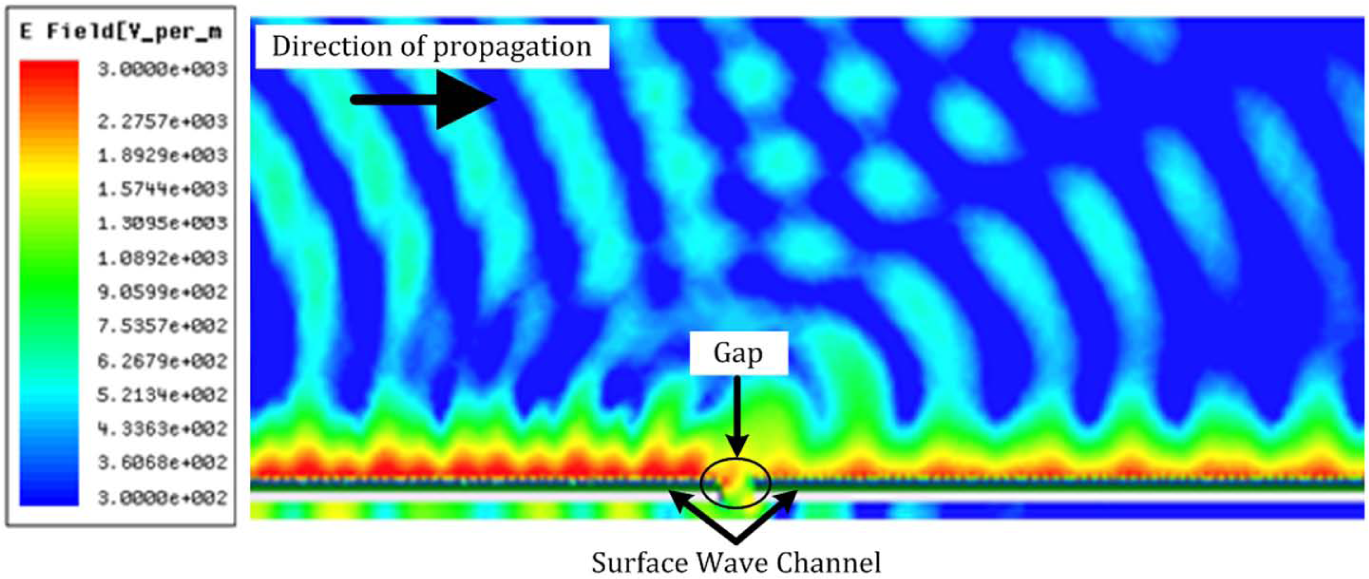
Simulation showing the complex magnitude electric field when a 5-mm air gap is introduced into the channel
In summary, although there will be some loss associated with each area of damage, if the total damaged area is limited to perhaps a couple of wavelengths, a complete communication failure should not occur. A certain level of damage can be included in the link budget, meaning that repairs can be made at a convenient time and will not require rerouting of cables. In addition, the modular design of the platform means that subsystems can easily be removed to allow access to the damaged area for repair. Finally, the mechanical simplicity of the channel means that no specialist tools or training are needed to effect repairs. This results in increased platform availability and reliability while reducing through-life engineering costs.
C. Health monitoring and reducing ‘No Fault Found’ diagnostics
Structural health monitoring (SHM) is becoming an integral part of platforms. SHM allows for prognostic data collection, resulting in maintenance and servicing occurring when required rather than at predetermined intervals. It can also predict if a catastrophic event is likely to occur and therefore be prevented with a targeted repair. Both of these factors increase availability, reliability and reduce through-life costs.
So why are not all platforms using SHM sensors? Unfortunately, the current techniques available for SHM, such as optical fibres and acoustic emissions, can only be applied to limited areas and do not provide wider platform coverage. 6 They also suffer the same problems as any other sensors: how do they communicate without wires? SHM sensors are frequently daisy chained together meaning that if a single sensor fails, the entire branch would no longer be able to communicate.
As has already been shown, surface waves can jump gaps and holes; however, there is loss associated with this. In addition to some of the surface wave being radiated, a portion will be reflected by the edges of the penetrating damage. This reflection occurs as there is a surface impedance change. A Zenneck surface wave channel requires an inductive reactive surface impedance (provided in this case by the meta-material surface of the channel) to propagate. Changes to this surface produce changes to the surface impedance, which result in radiation and backscattering of a proportion of the surface waves depending on the size and nature of the change. Thus, if an area of the platform is thinning creating integrity issues, it would also cause reflections and thus be detectable.
If a platform was coated with the surface wave channel, one can envisage the use of a 2D form of time domain reflectrometry (TDR) using surface waves to detect in real time if and where damage is occurring and estimate its severity. 7 TDR techniques work by sending a pulse along a cable to determine if there is an impedance mismatch, indicating the location of damage. At an impedance discontinuity, some of the signal will be reflected, and the delay will indicate the position of the damage. If no damage is present, the entire transmitted pulse will be absorbed in the termination.
Wider coverage of platforms is highly useful in terms of checking for damage; targeted inspection can be performed, reducing labour costs.
Although surface waves may not replace the full range of capability of existing SHM sensors, they could be used to complement and augment existing SHM systems. Surface waves would provide the much needed wider coverage area and would wirelessly connect the existing SHM sensors, removing single-point failures.
Alternatively, for platforms which do not currently have SHM sensors but are using surface waves for communications, the surface wave channel could provide a cheap way of incorporating wide area coverage SHM. The channel correction factors for the communications link would be monitored. If damage occurs, the correction factors would change, alerting maintenance crews that a repair is required.
An example of an implementation of a combined SHM/sensor system is shown in Figure 4 where stress, temperature and airspeed sensors are all linked to a surface wave communication bus (shown in light blue) along the wing of the aircraft. In addition, damage to the wing can be detected through the use of TDR along the surface wave channel.
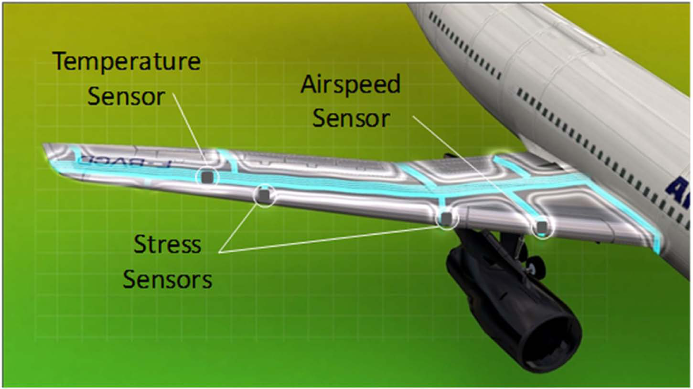
Concept implementation of networking sensors on the wing of an aircraft using surface waves
In terms of reducing ‘no fault found’, surface waves cannot directly address this problem; however, if platforms’ health can be monitored more widely and in real time, this will provide valuable diagnostic information. The diagnostic information will assist in recreating the exact circumstances that occurred when the fault was detected, hopefully reducing the possibility of ‘no fault found’.
IV. Summary
This article has provided a brief overview of the use of surface waves to reduce through-life engineering costs in terms of increasing flexibility, reliability and SHM coverage. Through simulations, measurements and demonstrations, it has been proven that surface waves are a viable alternative to traditional wired and wireless solutions. Use of surface waves will provide significantly more flexibility in terms of design for system architects. This is of particular benefit when changes are needed to be made to platforms, for example, during repairs and upgrades.
Footnotes
Funding
This work has formed part of an Engineering Doctorate (EngD) funded by the EPSRC. The initial work that has resulted in further studies was funded by the Systems Engineering for Autonomous Systems (SEAS) Defence Technology Centre (DTC) established by the UK Ministry of Defence.