
Abstract
This article begins by discussing the use of infrared thermometry to monitor the temperature of bearings. The reliability of a system using this type of sensor is estimated, and its suitability for use in an explosion protection technique is examined. Finally, some of the aspects of the intrinsic safety of the system, in particular the safety at high temperatures, are outlined.
I. Infrared Bearing Monitoring
Over a period of time, bearings can wear down causing an increased friction in the bearing housing. If left unfixed, this would eventually lead to a failure of the bearing housing, which could lead to extensive damage to the machine and the plant. In hazardous area applications, the danger is far greater since the increase in temperature could lead to the ignition of flammable gases or dusts. It is therefore essential that the temperature of the bearing housing be continuously monitored to ensure that any increase in temperature due to bearing failure is detected long before it becomes critical.
There is a wide variety of contact temperature sensors available for measuring the temperature of bearing housings. These are usually in the form of thermocouples, thermistors or platinum resistance thermometers (PRTs). To measure the temperature of the bearing housing using a contact thermometer, it is necessary to mount it onto the surface of the housing. Mounting anything onto the machine in this manner is not desirable, however, as the integrity of the machine could be compromised. Some temperature sensor manufacturers have sought to overcome this problem by incorporating the temperature measurement into the existing grease zerk thread. This allows for a contact measurement without compromising the integrity of the housing.
A major disadvantage of using contact temperature sensors to measure the temperature of bearing housings is that the contact sensor will experience high levels of vibration. This can lead to breakage of the thermocouple junction or the sensitive PRT element. The temperature sensor breakages are likely to occur far more frequently than the critical temperature rises, which they are installed to detect. Therefore, the machinery must be shutdown at regular intervals in order to check or replace the temperature sensor. This can be a costly exercise as any machine downtime leads to a reduction in productivity. A further disadvantage of contact temperature sensors is that the response time can be in the order of minutes. This is particularly true of PRTs, which consist of an element embedded in an outer housing. Since there is an air gap between the outer housing and the element, the response time is slowed by the low thermal conductivity of the air. When attempting to detect a rise in temperature that could potentially cause an explosion, the response time should be as short as possible since an early warning is essential.
Infrared (IR) temperature measurement is a technology that can deliver a short response time and vibration immunity, which is desirable in these applications. IR thermometers allow the user to measure the temperature of a surface without making contact with it. This is particularly useful in applications where the surface to be measured is moving or rotating. It is also useful for measuring the temperature of high-voltage switchgear, where contact temperature sensors carry the risk of electrocution. An IR temperature measurement works on the principle that all surfaces emit electromagnetic radiation relative to their temperature, and the magnitude at a given wavelength is defined by Planck’s law of blackbody radiation. By measuring the emitted energy over a known waveband, the temperature of the surface can be calculated using the integral of Planck’s equation over that waveband.
IR temperature sensors are widely used in many different industries, including food, paper, plastics and metals. The range of sensors available is extensive, covering many different wavebands specifically chosen for specific applications. The price of the sensors ranges from tens to thousands of pounds depending on the requirements of the application. For example, measuring the temperature of paper is relatively straightforward due to the high emissivity of the paper and limited temperature range required. For these applications, low cost sensors can easily be used. In order to measure the temperature of molten metals, however, it is necessary to measure the emitted energy at multiple wavebands to compensate for the low and changing emissivity. These instruments command a high price due to the complexity of the instrument and the algorithms contained within.
IR temperature sensors are available with many different outputs to suit specific applications. These range from the commonly used 4–20 mA analogue signal to digital communications such as USB or RS485 MODBUS. Sensors are also available with alarm relay outputs, which can be directly linked to warning systems.
Intrinsically safe IR thermometers are not yet commonly available. Although there are sensors that are certified intrinsically safe, they are very expensive and are usually only considered when contact temperature measurement is impossible to implement. As described above, there is a need to measure the temperature of bearing housings in order to prevent hazards. The IR temperature sensor described in this article tackles this problem in a novel way ( Figure 1 ).
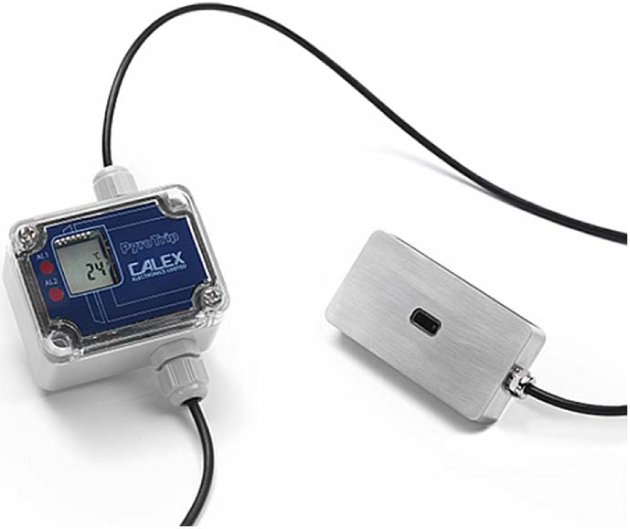
Sensor and transmitter/alarm unit
This sensor comes in two parts: a stainless steel sensing head and a miniature transmitter/alarm unit. The sensing head is specially designed for monitoring non-reflective surfaces from close proximity. As shown in Figure 2 , it has a wide field of view to capture energy from a large target area over which it averages the temperature. The sensing head can also withstand ambient temperatures as high as 150 °C without cooling. It is roughly the size of a matchbox and made of stainless steel for strength and corrosion resistance. Classified as simple apparatus, the sensing head may be mounted in hazardous area Zones 0, 1 and 2 for gas, and connected over distances of up to 500 m to zener barriers in the safe area. The response time of this sensor is 3 s, which is significantly faster than an equivalent contact thermometer. With a measurement temperature range of 0 °C–250 °C, it is suitable for a wide variety of monitoring applications. A major advantage of this type of sensing device is that the instrument can be both checked and replaced without any interference with the process. This is due to the fact that it is not directly mounted to the surface being measured.
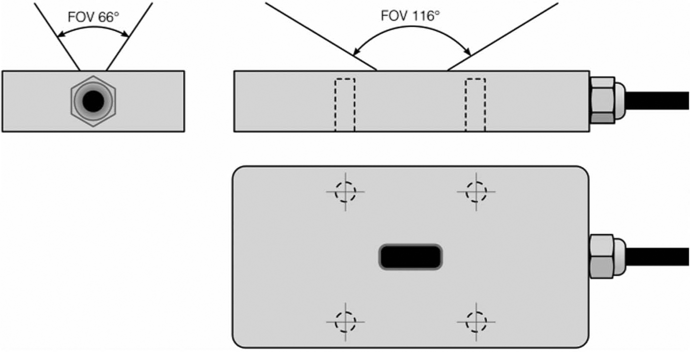
Field-of-view
The miniature transmitter/alarm unit is located in the safe area and provides a 4–20 mA output proportional to the measurement range of 0 °C–250 °C. It also has two configurable alarm relay outputs, a liquid crystal display (LCD) and light-emitting diode (LED) status lamps. Beneath the clear lid of the enclosure, there are simple push-button controls that permit alarm configuration and screw terminal blocks that can be removed to make wiring easier. The housing is made of polycarbonate, sealed to IP65.
II. Reliability Analysis of Monitoring System
The required safety integrity level (SIL) rating of the monitoring system is determined by the acceptable probability of failure to anticipate bearing failure. This probability is determined by the combined failure rate of the bearing and the monitoring system. Usually, establishing the probability of the temperature rise occurring is difficult, but this is the necessary first step in establishing the overall risk. A significant problem is that (as far as is known to the authors) the acceptable overall risk of an explosion is not defined and arguably is different for every installation. The same is true for operational failure, and consequently, each situation must be considered as a separate case.
There are many applications where the detection of an unacceptable temperature rise is desirable. In the specific case of hazardous areas created by flammable gases, the avoidance of temperatures greater than the ignition temperature of the hazardous gas is desirable. The majority of hazardous gases have ignition temperatures above 150 °C. Only carbon disulphide and ethyl nitrite of the gases listed in IEC 60079-20 have ignition temperatures below this (95 °C). Consequently, temperature rise in mechanical devices such as bearings usually creates an operational failure before it becomes an ignition risk. Bearing collapse can cause an ignition risk, which means operational failure and explosion risk may be correlated.
Until recently, where a monitoring system was used to enhance the safety of a Zone 2 located pressurised system, the failure of the pressurisation resulted in the activation of an alarm sometimes followed by isolation after a period of time. Immediate isolation was required for a Zone 1 installation. A more recent Comité Européen de Normalisation Électrotechnique (CENELEC) standard EN 50495:2010 attempts to address the reliability aspects of these monitoring systems. Table 1 summarises the requirements.
Minimum requirements for SIL and fault tolerance of a safety device
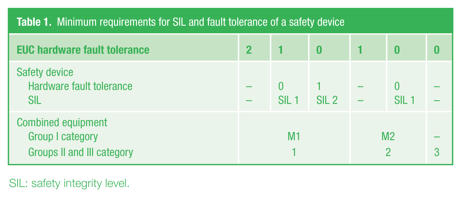
SIL: safety integrity level.
Table 1 proposes no requirements for Category 3 (Zone 2) safety systems. Presumably, this is based on the assumption that the failure rate in normal operation of all equipment used in Zone 2 is an acceptable risk. This is puzzling, since, for example, temperature monitoring of motor windings in Zone 2 is not unusual.
The desirable SIL rating of the system under discussion is largely determined by the probability of the anticipated temperature rise occurring. Almost all the failures to danger of the system are detectable if the receiving equipment recognises a signal outside the 4–20 mA range as a fault. Since thermal effects normally have a significant time constant (30 s), detection of a rapid rate of change could further eliminate spurious signals. One obvious fault scenario is the obscuring of the optical path, but this would usually be detected by the rate of change mechanism or a significant fall in the apparent temperature. The quantification of the possibility of this fault occurring is particularly installation dependent and difficult to do with any degree of confidence. The failure rate of barriers is discussed at some length in an article in the HazardEx magazine of September 2010, but their effect on the rating of a SIL 1 or 2 system is not likely to be significant. If the optical path is accessible, it is easy to check that the system is active, and with frequent testing, the SIL rating can be improved.
In practice, using the two alarms on the transmitter/alarm unit to monitor a significant departure from the expected temperature, as indicated in Figure 3 satisfies the requirement for monitoring Zone 2 equipment. This system is arguably adequate for monitoring Zone 1 equipment. However, both these proposals are dependent on the probability of the temperature-related fault occurring and the reliability of the other equipment in the loop.
Temperature monitoring system
Provided that the object being monitored normally operates at a temperature above ambient, one of the alarms can be set to monitor a temperature below the expected temperature, and this would be a defence against the target being obscured. A means of disarming this alarm during start up would need to be devised. The other alarm would monitor an unacceptable rise in temperature. Alternatively, the two alarms could both monitor temperature rise: one monitoring a small rise and creating a warning and the other isolating the equipment being monitored if the temperature rise is greater.
The alarms are usually set as normally closed when energised and opened on alarm or power failure. This also ensures that an open circuit in the field wiring creates an alarm condition.
III. Some Aspects of the Intrinsically Safe System
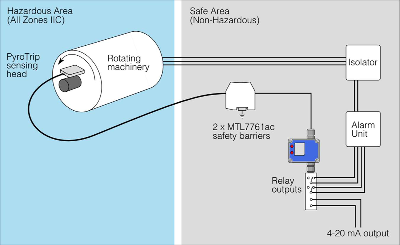
The system being considered is illustrated in Figure 4 . Essentially, the system is a ‘simple apparatus’ sensor connected by three wires via shunt-diode safety barriers to receiving equipment in the ‘safe’ area. The sensor can be mounted in any hazardous zone and is suitable for use in all gases. The sensor can operate at service temperatures of 150 °C, and this requires special consideration.
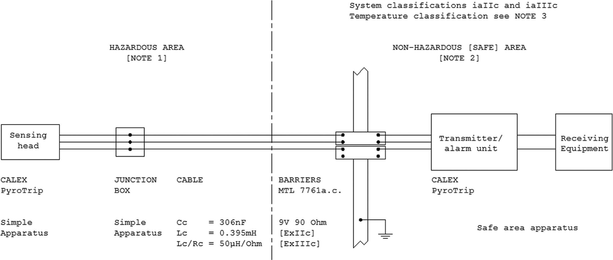
System diagram
The following discussion is based on the assumption that the sensor is positioned in a Zone 0 or 1, requiring an ‘ia’ or ‘ib’ system. Because of this, a factor of safety of 1.5 on the ignition current and voltage and a dual fault count are considered. Where the detector is mounted in Zone 2, the requirement is for an ‘ic’ system, and a unity factor of safety is used and normal operation considered. Only the ‘ia’ analysis is considered since the resulting requirements do not impose any impractical restrictions, and any Zone 2 use is more than adequately safe.
A. Barriers
The barriers used are MTL 7761 barriers with a safety description of 9 V, 100 mA. The signal available from the sensor is a low millivolt signal from a high impedance source. Since a leakage in the order of nanoamps would adversely affect the accuracy of measurement, a higher voltage barrier than usually used for millivolt signals is used. The resultant higher end-to-end resistance is acceptable because of the high source impedance.
That the combination of three channels of MTL 7761 meets the requirements of an ‘ia IIC’ source can be readily demonstrated using the techniques of the system standard IEC 60079-25. However, it is desirable to maintain the service temperature of the sensor as 150 °C in the hazardous area, and this is outside the temperatures considered in the international standards (IS). Unfortunately, there is very little experimental evidence from which to derive guidance. It seems reasonable to assume that a gas heated to its ignition temperature requires no further addition of spark energy to ignite. There is some slight confusion because the most incendive mixtures for spark ignition and temperature ignition are not necessarily quite coincident. It is generally agreed that ignition energy decreases as temperature increases, but the rate of change is not well defined. Some research suggests that the rate of decrease is quite slow until the temperature approaches that of the ignition temperature, and then, it accelerates quite rapidly. A further complication is that at low voltages, the permissible current is heavily influenced by the threshold voltage and the variation of this with temperature is not well documented. Fortunately, the gases have low ignition temperatures (less than 200 °C) in the IIA or IIB gas groups, and consequently, if a IIC system is used there is a further factor of safety. The exceptions are carbon disulphide (95 °C and IIC) and ethyl nitrite (95 °C and IIA), but these gases always present problems and require specific expertise.
The analysis of the barrier combination yields two sources of power. These are 9 V, 300 mA and 18 V, 133 mA. The permitted current in IIC corresponding to 9 V is 3.33 A, and hence, there is a large safety factor that increases the existing safety factor. The permitted current is determined by the capabilities of the test apparatus, and this barrier configuration would only become significant if the threshold voltage changes significantly with temperature. The current corresponding to 18 V in IIC is 440 mA and in IIB 1110 mA; hence, the factor of safety on current in IIB is 12.5 (using the 1.5 factor of safety), which is a factor of 156 on energy. With this safety factor, provided that the temperature of the gas is 10 °C below its ignition temperature, the system can be considered to be adequately safe.
The subject of the safety of intrinsically safe circuits being acceptable outside the usual temperature range of −40 °C–70 °C is being considered by the relevant IEC committee, and possibly, some requirements will emerge in about 5 years time. The task is made more difficult by the lack of experimental evidence, and this would require an enormous investment in terms of time and money to collect. A comforting fact is that intrinsically safe thermocouples have been used to measure high temperatures for years without incident. The delightfully incongruous existence of flameproof thermocouples certified as T6 is also worthy of comment. At present, there is no alternative but to do a risk analysis of each system and use large factors of safety and try to avoid getting close to the ignition temperature of the gas.
B. Sensor
The sensor is essentially two resistors and hence meets the criterion for simple apparatus. These can be summarised as requiring that the apparatus does not generate or store a significant amount of energy and is adequately insulated from earth.
The temperature classification of the sensor is determined by its service temperature and the temperature rise of the sensor under fault conditions. The barrier combination can deliver 675 mW into a matched load of 30 Ω or 600 mW into 135 Ω. These values can only be achieved by an improbable combination of cable faults. The resistance of the thermistors is high (3370 kΩ at 25 °C), and the probability of their failure to the matched resistance is very low (arguably less than one per million hours); therefore, this possibility can be discounted. One thermistor is thermally bonded to the mounting block and is held at the service temperature. A practical experiment applied 24 V to the sensor, and this produced a temperature rise of 3 °C in the unbonded thermistor and a 1 °C rise in the mounting block. On this basis, it is prudent to allow for a 5 °C rise in the temperature of the sensor. The temperature rise only occurs in a small area, and this gives a further factor of safety. The standard requires a 5 °C margin, and consequently, the temperature classification utilises the service temperature plus 10 °C. Using this argument, the sensor would have a T4 temperature classification up to 125 °C, and above that, comparing the service temperature plus 10 °C with the ignition temperature of the gas is the technique to be used.
C. Cables
The barrier combination yields the following output parameters for Cc: 300 nF, Lc: 395 µH, and Lc/Rc: 50 µH/Ω, and since the sensor has no input capacitance or inductance, these can be used for the cable between the sensor and barriers. The cable used is selected so as to withstand the possible 150 °C service temperature. The cable parameters are 92 Ω/km (at 20 °C), 300 nF/km, 1.2 mH/km and 13 µH/Ω.
The output parameters for the barrier are derived with service temperatures of −40 °C to +70 °C in mind, and possibly, these should be reduced for higher temperatures. Recent experimental evidence, which was used in framing the FISCO aspects of the IS standards, suggests that the effects of distributed cable capacitance and inductance are considerably less than the concentrated values. Consequently, the need to reduce the values may not be as great.
The permitted Lc/Rc is very large (and the Lc/Rc ratio of the cable decreases with temperature), and consequently, the inductive effect can be ignored. The usual length of the cable is quite short (50 m) and is restricted to 500 m, which gives a minimum factor of safety of 2 on the permitted capacitance. At 18 V, the 1.5 factor of safety on voltage creates a factor of safety of 4.5 on capacitance, giving a total safety factor of 9 in IIC. If the gas is classified IIB, the total safety factor is 60. These safety factors ensure that the system is adequately safe provided a 10 °C margin below the ignition temperature is maintained.
IV. Conclusion
The system is adequately safe as an intrinsically safe system for use in all gases and all zones up to a service temperature of 150 °C with the exception of carbon disulphide and ethyl nitrite. Three other gases listed in IEC 60079-20 would need to be treated with some caution if a 150 °C service temperature exists. These are 113-triethoxybutane (165 °C, IIA), di-tert-butylperoxide (170 °C, IIB) and dipentyl ether (171 °C). However, the probability of a high service temperature existing when these gases are being used is not high for other reasons.