
Abstract
Separators are considered a key component in lithium‐ion batteries (LIBs); however, currently commercial polyolefin separators fall short in meeting the demands of high‐performance LIBs due to their low porosity and other issues. In this paper, a novel coaxial electrospray/electrospinning device consisting of an outer nozzle and an inner nozzle is presented, which can simultaneously prepare composites containing nanofibers and nanoparticles. With this device, a new type of LIB separator was successfully fabricated by simultaneously spinning fibers of PVDF and spraying particles of KH570/SiO2 in situ onto an ultra‐high molecular weight polyethylene (UHMWPE) separator. The average diameter of the fibers prepared from the inner nozzle is 0.46 μm, and the average diameter of the particles prepared from the outer nozzle is 70.81 nm. According to the analytical results, the porosity of the separator increases from 37.85% to 81.33%, and the longitudinal shrinkage decreases from 7.28% to 2.63% compared to the unmodified separator. Additionally, the initial charge/discharge specific capacity of the experimental separator increases from 107.8 to 152.0 mAh·g−1. Excellent cycling stability of the separators is also exhibited after 50 charging and discharging cycles.
Keywords
1. Introduction
With the rapid development of portable electronic devices and new energy, the global demand for lithium‐ion batteries (LIBs) is rapidly increasing [1–7]. LIBs are composed of positive electrodes, negative electrodes, separators, and electrolytes. Among these components, separators play a crucial role in preventing the leakage of electricity between positive and negative electrodes, facilitating lithium ion transport, and ensuring the safety and overall performances of batteries [8]. However, commercial polyolefin separators have several limitations, such as low porosity, poor temperature resistance, and wettability, making it challenging to meet the requirements of high‐performance LIBs [9–11]. Therefore, the research on high‐performance nanofiber separators [12, 13] has become a research hotspot.
One of the simple methods for producing nanoparticles and coatings with potential applications in lithium batteries is electrospraying [14–17]. Electrospinning nanofibers have garnered widespread attention in the field of LIBs owing to their nanostructure characteristics, including high porosity, a large specific surface area, and low weight [18–20]. Recently, Yu et al. [20] prepared a novel type of LIB interlayer separator by electrospraying, exhibiting a high electrolyte absorption rate and a remarkable conductivity of the gel polymer electrolyte highly at 2.06 × 10⁻³ S·cm−1, along with a first charge and discharge capacity of 149.7 mA·hg−1. Similarly, Liu et al. [21] prepared ultra‐high molecular weight polyethylene (UHMWPE) LIB composite separators through electrospraying. The results demonstrated an increased porosity of the composite separators from 46.5% to 73.1% and a reduced longitudinal thermal shrinkage rate from 2.6% to 1.3%. After 50 charging and discharging cycles, the separators still exhibited good cycling stability. Widiyandari et al. [22] also prepared polyvinylidene fluoride (PVDF)/SiO2 lithium‐ion fiber separators by electrospinning, achieving a porosity of up to 70% and stable existence for 30 min at 150°C. Additionally, Li et al. [23] prepared PVDF/DPI nanofiber separators through electrospinning, with remarkable electrolyte absorption (522.4%) and ion conductivity (1.14 × 10⁻³ S·cm−1).
As mentioned above, electrospinning is a continuous process that allows the preparation of nanofiber separators with specific mechanical strength and porosity by adjusting spinning process parameters. When the electrospun nanofiber separator acting as nanofillers is combined with the electrospraying particles, it may enhance the mechanical strength of the composite separator through a three‐dimensional (3D) framework. However, existing methods for combining electrospinning fibers with electrosprayed particles mostly involve the hot‐pressing method. For example, Gong et al. [24] employed a combination of electrospinning, electrospraying, and hot pressing to create a PPESK fiber/PVDF bead composite lithium battery separator, while Kang et al. [8] also prepared polyisophthalamide (PMIA) and polyepoxyethane (PEO) composite polymer electrolytes using a similar approach but with different solution extrusion times. Unfortunately, this method does not allow simultaneous electrospraying and electrospinning, potentially causing particles to melt onto the fibers, resulting in larger fiber diameters and lower separator porosity.
To address these limitations, this paper presents a new coaxial electrospraying/electrospinning technology, enabling the simultaneous preparation of the composite separator containing both nanoparticles and fibers within a 3D framework structure. The simultaneous presence of particles and fibers increases the separator’s surface area, providing more adsorption sites. This allows the electrolyte to better contact and be adsorbed by the separator, thereby enhancing ion transport efficiency.
2. Experiment
2.1. Materials
PVDF: product code 44080, relative molecular weight 534,000, Alfa Aesar A Johnson Matthey Company; Acetone:Analytical pure, Beijing Chemical Plant; SiO2: particles with average diameter of 70nm; Hebei Yanbang Chemical Technology Co., Ltd.; N. N‐Dimethylformamide (DMF): analytically pure, Beijing Chemical Plant; UHMWPE diaphragm: model SG20B, relative molecular weight 1.8 million, Hebei Jinli New Energy; γ‐Methacryloxypropyl trimethoxysilane (KH570), concentration ≥ 98%, Sinopharm Chemical Reagent Co Ltd.
2.2. Experimental Process
2.2.1. Preparation of Spinning Solution and Spray Solution
A 17 wt% PVDF spinning solution was prepared in a mixture of acetone and DMF (in a ratio of 1:2). SiO2 is grafted with KH570 at a mass percentage of 10%. Then, a certain amount of KH570/SiO2 was added to the mixture of acetone and DMF (in a ratio of 1:2) to formulate the KH570/SiO2 spray solution. The concentration of the spray solution ranged from 0.1wt% to 0.5wt% with a concentration gradient of 0.1wt%. Both the spinning solution and the spraying solution were magnetically stirred for about 2 h and ultrasonicated for 1 h to ensure the formation of a homogeneous solution.
2.2.2. Coaxial Electrospraying/Electrospinning
Coaxial electrospraying/electrospinning was performed using a vertical setup containing a variable high DC voltage power supply. PVDF spinning solution was poured into the core cavity, while the KH570/SiO2 spraying solution was poured into the shell cavity. The coaxial nozzle consists of an inner nozzle with an inner diameter of 0.4 mm and an outer nozzle. These nozzles are mounted coaxially and grounded using an alligator clip. The inner diameter of the inner nozzle was fixed, while the outer diameter was used as a process parameter. The electrospinning parameters used were selected based on preliminary tests.
2.2.3. Preparation of Composite Separator
A 6 × 6 cm UHMWPE separator sheet was laid flat on the receiving device with a receiving distance of 10 cm, a voltage of 23 kV, a concentration of KH570/SiO2 spraying solution of 0.3wt% and a concentration of PVDF spinning solution of 17wt%, and a controlled time of 2, 4, 6, and 8 min, respectively, to obtain the composite separator and to test its performance. Figure 1 shows the schematic diagram of coaxial electrospraying/electrospinning for simultaneous fiber/particle preparation.

The schematic diagram of the simultaneous preparation of fibers/particles by coaxial electrospraying/electrospinning.
2.3. Testing and Characterization
2.3.1. Scanning Electron Microscope (SEM) Analysis
After the composite separator was fully dried, a sample of appropriate size was cut out and was fixed on the sample stage of the SEM using double‐sided carbon conductive tape, which was sprayed with gold and the surface morphology of the separator was characterized using the SEM.
2.3.2. Porosity of the Composite Separator
Porosity is measured based on the volume of liquid absorbed by the separator. First, the weight of the separator was measured as M1, then soaked in n‐butanol for 2 h, and measured weight of the wet separator as M2 after removing the liquid from the surface. The porosity can be calculated by following formula:

2.3.3. Dimensional Stability of the Composite Separator
Take the separator of diameter R and place it in an oven. After heating at 90°C for 1 h, observe the changes in the diaphragm.
2.3.4. Electrochemical Performance Test of Composite Separators
The cathode material was prepared from lithium iron phosphate (LiFePO4), carbon black, and PVDF solution (a mixture of 8% PVDF and NMP) in a mass ratio of 8:1:1. The anode material was lithium metal. The cell was then assembled with the diaphragm in a glove box. The prepared positive pole piece was lightly placed in the center of the positive shell, 80 μL of electrolyte was dropped in, and then the composite separator of the battery was put into the ordinary spray spinning modification, and the lithium pole plate, metal spacer, and shrapnel were put in the center, and then the negative shell was covered and the battery was encapsulated.
3. Results and Discussion
3.1. Assembly of Coaxial Electrospraying/Electrospinning Equipment
From Figure 2, we can see that the coaxial electrospraying/electrospinning device contains an outer nozzle and an inner nozzle. The outer nozzle is connected to the shell cavity to store the spraying solution; the inner nozzle is connected to the core cavity to store the spinning solution. The inner nozzle of the coaxial electrospraying/electrospinning device is used for electrospinning. Meanwhile, the outer nozzle is used for electrospraying.

(a) Coaxial electrospraying/electrospinning nozzle structure. (b) Coaxial electrospraying/electrospinning nozzle.
In the coaxial electrospinning technology, the Taylor cone formed by the polymer solution is drawn into a core‐shell fiber under the action of the electric field, and the core‐shell structure material was produced [25]. However, in our work, the separator containing particles and fibers can be produced in situ by the coaxial designed device. In this process, the particles were produced by the outer nozzle by adjusting concentration of the spray liquid and the fibers were produced by the inner nozzle by adjusting the gap of the outer nozzle and concentration of the spray liquid.
3.2. Determination of the Optimal Parameters for the Separator Preparation
Based on the above equipment, we prepared the PVDF&KH570/SiO2 composite separator by coaxial electrospraying/electrospinning. The concentration of the PVDF electrospinning solution concentration is determined to be 17wt%. SiO2 is grafted with KH570 at a mass percentage of 10% [26]. The concentration of the KH570/SiO2 spray solution concentration ranges from 0.1wt% to 0.5wt%, with a concentration gradient of 0.1wt%. Electrospraying tests were conducted using a nozzle with an inner diameter of 0.4 mm. The experiments were performed with a receiving distance of 10 cm and a voltage of 23 kV. The results are shown in Figure 3. It can be observed that the smallest particle, with a diameter of 70.81 nm, was obtained using a solution concentration of 0.3wt%. This concentration was selected for spraying from the outer nozzle.

Average diameter of KH570&SiO2 in different concentrations.
The separator, which contains particles and fibers, was tested in situ using a device with outer diameters of the inner nozzle measuring 2.644, 2.680, and 2.770 mm. The inner diameter of the outer nozzle is 3.0 mm. The microstructure of the composite separators was investigated using SEM, as shown in Figure 4. It can be observed that a separator with a 3D mesh‐like composite structure was successfully prepared using the optimal parameters, including an inner nozzle diameter of 2.680 mm, a receiving distance of 10 cm, and a voltage of 23 kV. The resulting separators have fibers with a diameter of 0.460 μm, carrying particles with an average diameter of 70.81 nm.

SEM image of co‐spraying effect using the device to adjust the outer diameter of the inner core nozzle: (a) 2.644 mm, (b) 2.680 mm, and (c) 2.770 mm.
3.3. Study on Properties of PVDF&KH570/SiO2 Battery Separators
The physical properties of the PVDF&KH570/SiO2 battery separators are listed in Table 1, the results show that the porosity of the PVDF&KH570/SiO2 battery separators increased from 37.85% to 81.33% at the process time from 2 to 6 min, and the pores are diffusely distributed across the separator, with an average pore size of 1 μm. The increase in porosity is due to the simultaneous spraying of particles and fibers, which results in the formation of a 3D structure. However, it decreases with the lengthening treatment time, indicating that the fibers and particles would densely pack on the surface of the separator, blocking the original micropores on UHMWPE as the experimental time increased [27]. From Table 1, the porosity of modified separators is consistently higher than that of unmodified separators. The shrinkage rates of both the transverse and longitudinal axes approach national standards, indicating that the dimensional stability of PVDF&KH570/SiO2 battery separators surpasses that of UHMWPE separators [28]. The longitudinal shrinkage in the PVDF&KH570/SiO2 battery separators decreases from 7.28% to 2.63%. However, there is no significant change in the transverse shrinkage ratio. The probable reason is that the UHMWPE separator is uniaxially stretched during the production process [29]. As a result, the longitudinal shrinkage ratio is larger than the transverse shrinkage ratio.
Porosity and dimensional stability of PVDF&KH570/SiO2 separator.
From Figure 5(a), we can see that the capacity changes from 107.8 mAh·g−1 in the untreated UHMWPE separator to 87.6, 117.3, 152.0, and 144.4 mAh·g−1. The variation pattern of the initial discharge specific capacity aligns with that of the porosity. This is because increased porosity leads to greater electrolyte absorption, and the resulting higher ion concentration within the battery enhances the initial discharge specific capacity. There is a tendency for the first discharge capacity, which increases first and then decreases as the coaxial spinning time is lengthened; the possible reason is that excessive particles and fibers are clogged in the micropores of the original separator, resulting in a decrease in porosity. In addition, the discharge capacity of the separator sprayed for two minutes is lower than that of the unmodified separator, which may be caused by insufficient separator absorption. The initial discharge capacity of the PVDF&KH570/SiO2 battery separators remaining is higher than that of the unmodified UHMWPE separator. It is presumed that the structure with a large specific surface area formed by the nano‐sized particles absorbs the electrolyte battery [30]. The highest porosity recorded in the experiment was 81.33% for the modified separator with a spraying time of 6 min, corresponding to a peak initial discharge specific capacity of 152.0 mAh·g−1. The 6 min sample also exhibited the smallest capacity decay after 50 cycles in terms of electrochemical cycling performance.
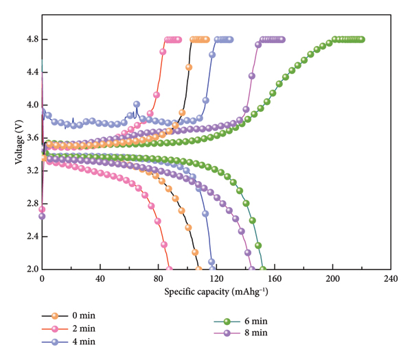
(a) First charge‐discharge ratio capacity. (b) Cycle of PVDF&KH570/SiO2 separator.
(b)

From Figure 5(b), the modified separators exhibited effective capacity retention. However, following 50 cycles, a decline in the capacity of all modified separators was observed. To analyze the reason for the decrease, an 8 min sample of the modified separator after 50 cycles was selected for SEM analysis, and the results are shown in Figure 6(a). After 50 cycles, the composite separator particles flattened, and the micropores formed between the particles and fibers disappeared, resulting in the collapse of the original 3D structure. As can be seen from the enlarged view of the circular portion in Figure 6(b), the fibers of the composite separator have fractured, leading to the formation of larger grooves. The collapse of the 3D structure of the composite separator, the fracture of the fibers, and the disappearance of the micropores indicate that the ability of the composite separator to store the electrolyte and facilitate ion transport is reduced. As a result, the charging and discharging cycle performance of the LIB is weakened.
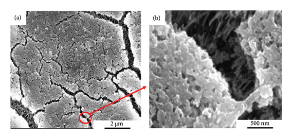
(a) SEM image of the separator after 50 cycles. (b) Localized enlarged schematic of the markers.
4. Conclusion
In this paper, a new method—coaxial electrospraying/electrospinning—was successfully implemented, which can simultaneously prepare composite materials containing nanofibers and nanoparticles. A novel LIB separator carrying KH570/SiO2 nanoparticle and PVDF fiber on UHMWPE separator was successfully prepared with this method. The porosity of the resulted battery separator increases from 37.85% to 81.33%, the longitudinal shrinkage decreases from 7.28% to 2.63%, and the initial charge‐discharge ratio of the experimental separator reaches 152.0 mAh·g−1, increasing 41.0% compared with the unmodified separator. This novel coaxial electrospraying/electrospinning method demonstrates great potential in high‐performance LIB separators, providing a promising avenue for future research and innovation in energy storage technologies.
Data Availability Statement
Data are available from the first author upon request.
Conflicts of Interest
The authors declare no conflicts of interest.
Author Contributions
Chengxi Xie and Juan Bai are co‐first authors. Taiqi Liu: writing–review and editing and funding acquisition. Chengxi Xie, Juan Bai, and Xuanzhi Zheng: methodology, formal analysis, visualization, and writing–original draft. Xiaomin Zhao: writing–review and editing. Jie Ren, Feixiang Wu, and Li Yang: data curation.
Funding
This study was funded by the Research Base‐Science and Technology Innovation Platform‐New Materials Research and Development Project (Project Code: 11011021001) and the Natural Science Research Foundation of Anhui Xinhua University (Grant No: 2022zr020).
Footnotes
Acknowledgments
This study was funded by the Research Base‐Science and Technology Innovation Platform‐New Materials Research and Development Project (Project Code: 11011021001) and the Natural Science Research Foundation of Anhui Xinhua University (Grant No: 2022zr020). We thank all the interviewees for sharing their ideas and experiences with us during our field studies and all the anonymous reviewers who helped us to improve the paper.