
Abstract
Polyaniline (PANI) and PANI/Ag2O/Ag composites I and II were prepared under different AgNO3 oxidant concentrations using the oxidative photopolymerization method. The chemical structure and optical, electrical, and morphological properties were determined for the prepared nanocomposite. The PANI/Ag2O/Ag composite II has the optimum optical properties, in which the bandgaps of PANI, composite I, and composite II are 3.02, 1.71, and 1.68 eV, respectively, with the morphology of a bunch of grape-like shapes with average particles sizes of 25 nm. Under the optimum optical properties, glass/PANI/Ag2O/Ag composite II electrode is used for hydrogen generation from sewage water. The measurements are carried out from a three-electrode cell under a xenon lamp. The effects of light wavelengths and temperature on the produced current density (
1. Introduction
Global energy demand is increasing rapidly, because of population and economic growth, especially in emerging market economies. While accompanied by greater prosperity, rising demand creates new challenges. Energy security concerns can emerge as more consumers require ever more energy resources. And higher consumption of fossil fuels leads to higher greenhouse gas emissions, particularly carbon dioxide (CO2), which contribute to global warming. Moreover, there are additional gases such as SOx and NOx that have fatal and hazardous effects on plants, animals, humans, and the environment [1–4]. At the same time, the number of people without access to electricity remains unacceptably high.
Many studies were carried out for providing other renewable energy sources such as solar energy, geothermal heat, biomass, and wind. Solar energy is a promising renewable energy source with its applications in photoelectrochemical water splitting reactions [5–8]. This reaction is based on the electron generation under light irradiation, in which the outer energy levels split under this irradiation and cause the hole-electron generation. Both electrons and holes share in the water splitting reaction through the motivation of the H2O molecule for converting to hydroxyl radicals [9, 10]. The water splitting reaction produces hydrogen gas, which is a promising fuel for the combustion process without any contamination or carbon residue. In addition, this gas has a high energy capacity that can be used in factories, cars, airplanes, and spacecraft.
The gas generation from water splitting is carried out using a semiconductor oxide material such as Cu2O, ZnO, WO3, TiO2, and Fe2O3 [11–16]. Metal sulfides such as PbS and CdS can be used as photocatalytic materials for the water splitting reaction and hydrogen generation, but with low efficiency and with some corrosion limitations [17–19]. Sometimes, the carbon materials such as g-C3N4 and carbon nanotube have the photocatalytic behavior for water splitting reaction.
Conducting polymers such as PANI and its derivatives are considered promising materials for photocatalytic water splitting reactions. These polymers have great advantages represented in the high surface area, stability, safety, and reproducibility; moreover, they have commercial advantages of low cost and easy preparation [20–22]. The photocatalytic behavior of these polymers increases with increasing the surface area through the nanoscale or polymer composite preparations.
Among great materials as the noble metals such as Pt, Au, and Ag [17, 18, 23], these metals have a plasmonic property that captures the photons and generates electrons on their surface, in which an oscillation process occurs for these electrons. The generated energy is transferred to the neighbor semiconductor materials for more electron generations that finally reach the water molecules for a splitting reaction.
There were previous studies for using polymers as photocatalytic materials. Xiao et al. [24] studied WS2/poly(3,4-ethylene dioxythiophene)/Au photoelectrode for H2 generation from H2O. Mobidane et al. [25] synthesized a poly(3-aminobenzoic acid)/organic framework for hydrogen generation from H2SO4 solution. Thimsen et al. [26] studied the role of noble metals on Fe2O3 for hydrogen generation from NaOH solution. Moreover, Ghosh et al. [27] studied the contaminations decompositions using the thiophene polymer compounds using the photocatalytic behavior of this polymer. Also, Yin and Zheng [28] use the polymer (poly (diphenyl butadiyne)) for the removal of pollution from fiber materials.
Although the previous studies try to provide a renewable energy source instead of fossil fuels, there are still many limitations represented in the small
This work is promising for providing H2 gas as a renewable energy source from sewage water without using any freshwater or sacrificing agent. Moreover, the photoelectrode has high stability and reproducibility, in addition to its very low cost. The produced H2 moles are greater in comparison with the previous studies.
This work studies the preparation of PANI and PANI/Ag2O-Ag composites I and II for hydrogen generation from sewage water. Composite II is applied as a photoelectrode for hydrogen generation through the three-electrode cell. The effects of dark/light, light wavelengths, and temperature on the produced
2. Experimental Part
2.1. Materials
Aniline and AgNO3 were purchased from Rankem (India) and Winlab (UK) companies, respectively. DMSO was obtained from Sigma-Aldrich, USA. NaCl, Na2S2O3, CH3COOH, and NaOH were purchased from El-Nasr Chemicals Company, Egypt.
2.2. Preparation of PANI and PANI/Ag2O/Ag Composites
PANI was prepared by an in situ oxidative polymerization method, in which 0.1 M aniline was dissolved in acetic acid; in the same manner, 0.15 M (NH4)2S2O8 was dissolved. Then, a sudden addition was carried out, in which the green precipitate indicates the formation of the PANI. This powder is then washed well and dried at 60°C.
PANI/Ag2O/Ag composites are prepared by the oxidative photopolymerization process, in which AgNO3 is used as an oxidant. Two composites are prepared dependent on the AgNO3 concentrations: composite I and composite II are prepared by using 0.1 and 0.2 M AgNO3, respectively. An artificial light lamp is used (400 W) as the light radiation source. This radiation enhances the oxidation power of AgNO3. The gray-green precipitation indicates the formation of the precipitate.
2.3. Electrode for Hydrogen Generation
PANI/Ag2O/Ag II composite electrode is prepared for hydrogen generation. The preparation was carried out through oxidative photopolymerization on a glass electrode as shown in Figure 1(a). The prepared glass/PANI/Ag2O/Ag II electrode is washed well using the dist. water and dried at 60°C. This electrode is used as a working electrode, while graphite and calomel electrodes are used as counter and reference electrodes, respectively. The measurements are carried out from sewage water (chemical composition is mentioned in Table 1). The system of measurements is mentioned in Figure 1(b), in which the measurements are carried out under an electrochemical workstation (CHI660E) using a xenon lamp.

(a) The preparation of the PANI/Ag2O/Ag composite and (b) the electrochemical system of hydrogen generation through an electrochemical PowerStation and a xenon lamp.

The chemical composition of the sewage water-electrolyte for H2 production.
2.4. Characterization of the Prepared Nanomaterials
The chemical structure and morphology of the prepared PANI and PANI/Ag2O-Ag composites I and II are characterized using different analytical techniques. The X-ray diffractometer system (PX’Pert Pro, Holland) with Fourier transform infrared spectroscopy (Shimadzu FTIR-340 Jasco spectrophotometer) confirms the chemical structure and function groups while the scanning electron microscope (ZEISS Gemini Column) analyzed the morphology. The UV spectrophotometer (M160 PC) determines the optical analyses.
3. Results and Discussion
3.1. Characterization of the Prepared Nanomaterials
The chemical structures and functional groups of PANI and PANI/Ag2O/Ag composites I and II are confirmed using the FTIR analyses as shown in Figure 2(a). Table 2 summarizes the peak positions for the function groups. For the PANI, the function groups N-H, C-H aromatic, and C-N are located at 3401, 3051, and 1105 cm-1, while the C=C quinoid and benzenoid rings are located at 1467 and 1301 cm-1, respectively. Moreover, the C-H in the plane and paradisubstituted rings are located at 870 and 787 cm-1, respectively. After the composite formation, there are redshifts in the band positions related to N-H, C-H aromatic, C=C quinoid, C=C benzenoid, C-N, and C-H in the plane. While there are blueshifts in the band related to the paradisubstituted aromatic rings. These shifts are related to the effect of Ag2O and Ag on the N atom in the nanocomposite [33].
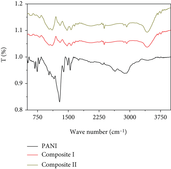
(a) FTIR and (b) XRD analyses of PANI and PANI/Ag2O-Ag composites I and II.

The FT-IR spectra of PANI and PANI/Ag2O-Ag composites I and II.
The XRD analyses of PANI and PANI/Ag2O-Ag composites I and II are shown in Figure 2(b). The XRD pattern of PANI (black line) shows the semicrystalline nature of the polymer related to the presence of three peaks located at 15.02, 20.78, and 25.55°. These peaks correspond to the growth directions (011), (020), and (200), respectively [34–36].
With the formation of PANI/Ag2O-Ag composite I, there is the appearance of new peaks related to the Ag2O at 32.3, 46.6, and 54.7° [37, 38]. Moreover, there is the appearance of new peaks related to the cubic Ag nanoparticles at 38, 44.3, 64.5, and 77.5°. These peaks have higher intensities than observed for Ag2O in the growth directions (111, (200), (220), and (311), respectively [39].
In composite II, the peaks related to the Ag nanoparticles have almost the same positions in composite I. While the Ag2O nanoparticles are located only at 32.13° and have the growth direction (006), the PANI indication peak is located at 34.08° through composite II, the peaks related to Ag nanoparticles increase at the same time, and there is a disappearance of peaks related to the Ag2O in the composite.
Using the Scherrer equation (1) [23], the average crystalline size of Ag nanoparticles is 23 nm at 38°. This equation depends on full width at half maximum
The morphological analyses of the PANI and PANI/Ag2O-Ag composites I and II are estimated by SEM analyses as shown in Figures 3(a)–3(c)). Moreover, the cross section and morphologies are confirmed by the theoretical modeling ImageJ program as shown in Figures 3(d)–3(f)). From Figure 3(a), the irregular shape of PANI appears well with porous nature and agglomerated network. This behavior is confirmed in Figure 3(d) using the modeling study. The high porosity and surface roughness are confirmed.
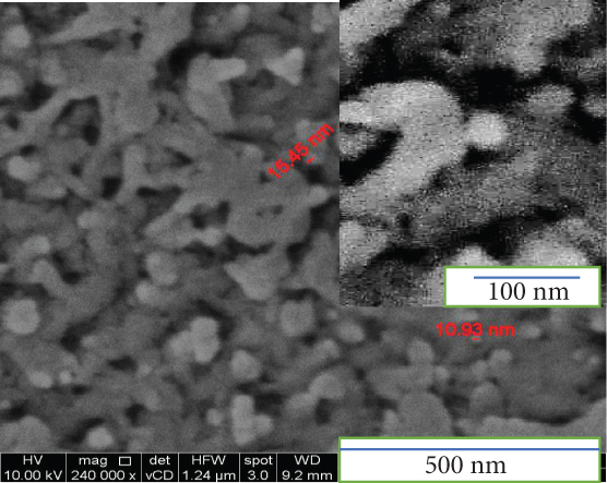
SEM and ImageJ modeling of (a, d) PANI, (b, e) composite I, and (c, f) composite II, respectively.


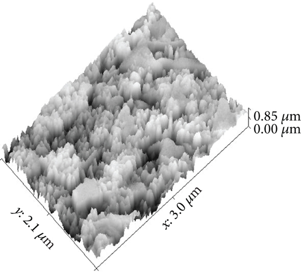
The morphology of composite I is shown in Figure 3(b). The Ag2O and Ag appear as small circular nanoparticles incorporated inside the PANI particles. The surface roughness and cross section appear well using the modeling image as shown in Figure 3(e). The rough surface confirms the presence of very small particles in the composite.
The morphology of composite II is shown in Figure 3(c); from this figure, the Ag2O and Ag increase very much in the composite; then, these small particles agglomerate on each other and form a bunch of grapes with white color. This morphology appears high clearly in Figure 3(f), in which the high roughness appears with more white color indicating the high percentage of Ag2O and Ag in the composite.
The optical analyses of the prepared PANI and PANI/Ag2O-Ag composites I and II are shown in Figure 4. The absorbance spectra of PANI are shown in Figure 4(a) (black line). PANI has three absorbance bands at 333, 439, and 600 nm. The absorbance peak at 333 and 439 nm in the UV and visible regions are related to the

(a) Optical absorbance of PANI and composites I and II. Bandgap values of (b) PANI and (c) PANI/Ag2O-Ag composites I and II.
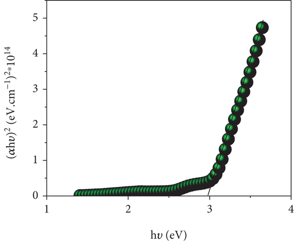

In the case of composite formation, there are more enhancements in the optical absorbance, in which the composite has the same peak at 333 nm, but there are increases in its intensity. The enhancements appear clearly in the peaks at 624 nm in the visible region. Composite II has the optimum absorbance behavior, in which it has the optimum intensity in the UV region and redshift in peaks at 624 nm. This is related to the effect of Ag2O and Ag nanomaterials in the composite. These materials have a plasmonic response that absorbs and captures the photons; then, these photons cause electron-hole pair formation, in which the excited electron reaches the neighbor PNAI surface. Finally, these electrons do oscillation resonance motion that causes the generation of current density on the surface.
The bandgap (
3.2. H2 Generation Test
The hydrogen generation under the sewage water splitting is carried out using the three-electrode cell, in which glass/PANI/Ag2O-Ag II is the working electrode, graphite is the counter electrode, and the calomel electrode represents the reference electrode. The chemical composition of the sewage water is mentioned in Table 1.
The measurements were carried out from 100 ml of sewage water without using any additional electrolytes. The measurements were carried out under the voltage (0 to 1 V) at 25°C.
Under the applied voltage in dark and light, the current density values (

The produced current density under dark and light for the PANI/Ag2O-Ag composite II at 25°C.
The effect of temperature (303 to 333 K) on the produced

(a) The produced current density under different temperatures and (b) the produced current density at +1 V for the electrode glass/PANI/Ag2O-Ag II. (c) The Arrhenius (black curve) and Eyring equation (red curve) relationship for calculation of the thermodynamic parameters.


The activation energy (
The relation between the produced

(a) The effect of wavelengths (390 to 636 nm) on current density for the electrode PANI/Ag2O/Ag II and (b) the produced current density at +1 V under different wavelengths.

The relation between the time and the produced

The relation between (a) the current density and time and (b) the produced H2 moles and time.
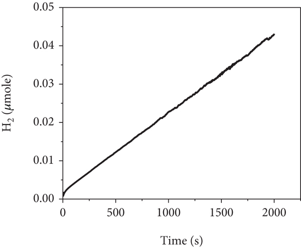
Quantitatively, the generated hydrogen moles as a function of the time are determined by Faraday’s law of electrolysis (6) [34] as shown in Figure 8(b).
where
3.3. Wettability Study
Measuring the contact angle (
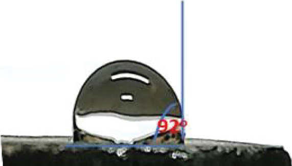
Contact angle values for (a) PANI and (b) PANI/Ag2O/Ag composite II.

Figure 9 shows the contact angle measurements; this test is carried out by dropping 0.1 ml H2O on the surface of PMT and PMT/roll-GO, in which this angle decreases from 92 to 41°, respectively. This enhancement is related to the effect of roll-GO for the enhancement of the surface morphology and the hydrophilic nature of the composite nanomaterials [50].
4. Conclusions
The photopolymerization method is used for the preparation of PANI/Ag2O/Ag composites I and II, by using 0.1 and 0.2 M AgNO3, respectively. The optical analyses confirm the enhancement of the optical properties of the composites in comparison with the PANI, in which the PANI/Ag2O/Ag composite II has the optimum optical properties with a bandgap of 1.68 eV. Glass/PANI/Ag2O/Ag composite II is used as an electrode for hydrogen generation from sewage water without using any additional electrolyte. The measurements were carried out under dark/light and different optical wavelengths and temperatures. At 3°C, the
Footnotes
Data Availability
The data that support the findings of this study are available from the corresponding author upon reasonable request.
Conflicts of Interest
The authors declare that they have no conflicts of interest.
Acknowledgments
The authors extend their appreciation to the Deanship of Scientific Research at Jouf University for funding this work through a research grant (no. DSR-2021-03-0322).