
Abstract
Material hardness of natural fiber composites depends upon the orientation of fibers, ratio of fiber to matrix, and their mechanical and physical properties. Experimentally finding the material hardness of composites is an involved task. The present work attempts to explore the deformation mechanism of natural fiber composites subjected to post-yield indentation by a spherical indenter through a two-dimensional finite element analysis. In the present work, jute-polypropylene, sisal-polypropylene, and banana-polypropylene composites are considered. The analysis is attempted by varying the properties of Young’s modulus of fiber and matrix, diameter of fiber, and horizontal and vertical center distance between the fibers. The analyses results showed that as the distance between the fiber’s center increases, the bearing load capacity of all composite increases nonlinearly. The jute fiber composite shows predominate load-carrying capacity compared to other composites at all
1. Introduction
Natural fibers are extensively used in the preparation of composites due to their low cost, low density, and biodegradable. The properties of natural fiber composite depend on source of fiber, fiber extraction, fiber preparation, fiber property, matrix preparation, matrix property, and fabrication process like hand molding, compression molding, injection molding, continuous pultrusion, and extrusion molding and their process parameters. Verma et al. [1] fabricated the alkali-treated sisal reinforced with starch and epoxy matrix biocomposites and investigated their mechanical and microstructure characteristics. The results revealed that epoxy-coated fiber composite showed improved property. Verma et al. [2] fabricated and experimentally characterized the jute and starch hybrid biocomposites. They concluded that water absorption significantly affected the mechanical properties of the composites. Verma et al. [3] investigated the mechanical and physical behavior of soy protein and sisal fiber-reinforced green composites. Vijay et al. [4] experimentally studied the raw and alkali-treated tridax procumbens fiber composites. The alkali-treated fiber-based composites showed improved thermal stability, tensile, and crystallinity. Dinesh et al. [5] investigated the influence of wood dust as fillers in the mechanical and thermal properties of jute –epoxy fiber composites. The results showed that padauk wood dust embedded composite improved the mechanical property, whereas rosewood dust enhanced the thermal stability of the composite. Jothibabu et al. [6] attempted to evaluate the hybridization effect on mechanical property through the different stacking sequence of areca sheath fiber/jute fiber/glass fabric fiber composites. Vijay et al. [7] examined the thermo-mechanical characteristics of Azadirachta indica seed powder and Camellia sinensis powder filled jute epoxy composites. Vijay et al. [8] studied the physical, chemical, thermal, mechanical, and morphological characteristics of treated and untreated Leucas aspera fibers. Vijay et al. [9] examined the physical and chemical properties of Vachellia farnesiana fibers. Sathish Kumar and Nivedhitha [10] studied the different weight fraction-based chemically modified kenaf fiber-epoxy composites. The results showed that 6% NaOH treated 40% weight fraction fiber composite showed improved mechanical property compared to others. The above natural fiber composites are fabricated with different orientation of fibers and ratio of fiber to matrix so finding their mechanical properties is an involved task. If a model or method is developed to find the mechanical properties in advance that may reduce cost and time incurred to fabricate the materials with required properties. Generally, the hardness values for the metallic materials are well known and are available in ASTM standard format, but the hardness values for natural fiber composites are unknown in most of the circumferences. Indentation-based hardness has direction benefits in different engineering applications like load-bearing mechanical elements and contact effects at different length scales in micro, meso, and macro applications. The pioneered indentation of metals was approached by Tabor [11]. The followers attempted in numerical, semianalytical, and analytical methods using different shapes of indenters indenting infinite half space to explore the plasticity role. Ishlinsky [12] attempted indentation of rigid perfectly plastic half space against a rigid sphere using the slip-line theory of plasticity and concluded that indentation hardness is three times of material yield strength, whereas Hill et al. [13] used flow theory for the same. Johnson [14] stated that indentation behavior of elastic perfectly materials against rigid indenter can be explored in deformation order of elastic, elastoplastic, and fully plastic deformations. Samuels and Mulhearn [15] explored the deformation behavior of half space against a blunt indenter and observed that subsurface deformation is in radial direction under the contact zone. The pioneer finite element method-based study was attempted by Hardy et al. [16], who detected that contact pressure changes from elliptical to rectangular and also observed that contact stress in axis symmetry is constant as the applied load increases. Follansbee et al. [17] compared their elastic-plastic indentation numerical results with the Hertz elastic solution and shallow and deep indentations experimental results and found good agreement with them. Giannakopoulos et al. [18] found constitutive relations for applied normal load and indentation interference using finite element method for elastic and elastic-plastic material against a Vickers indenter. Komvopoulos and Ye [19] observed the behavior rigid sphere indentation against an elastic perfectly plastic half-space through the finite element study. The developed constitutive equations showed good agreement with Johnson [14] and concluded that material hardness is three times the yield strength of indented material. Park and Pharr [20] explored the elastic and plastic dominant regimes in elastic-plastic indentation. Mesarovic et al. [21] detected a decreasing trend in mean contact pressure for larger indentation which leads to the failure. Bhattacharya et al. [22] studied the elastic and plastic behavior with finite element approach at submicrometer scale and compared with experimental results. They said that continuum-based finite element approach can relate load and indentation at submicrometer scale in a well manner, and Knapp et al. [23] developed finite element approach-based nanoindentation method to expose the elastic modulus and hardness of layered medium.
Apart from the indentation models, flattening models are also approach by different researchers. Kogut et al. [24] analyzed deformation of a sphere asperity against a rigid flat through finite element approach and deduced empirical relations for contact parameters with interference as variable. Chang et al. [25] called as CEB model assumed volume conservation at the tip of spherical asperity and offered a simplified analytical contact area and contact load solution for the elastic-plastic contact deformation behavior similarly Thornton et al. [26] who provided a simplified analytical solution based on elastic perfectly plastic collision of spheres with truncated Hertz contact pressure distribution.
Kocharski et al. [27] and Vu-Quoc et al. [28] provided more accurate finite element solutions with realistic elastic plastic deformation of spherical asperity during its loading, but they did not provide common solution for the global contact parameters. Kogut et al. [29] carried out a finite element-based loading and unloading of rigid sphere indentation in a half space for elastic-plastic materials. Meanwhile, Quicksall et al. [30] explored the effect of Young’s modulus and yield strength properties impact on single asperity flattening model. Jackson et al. [31] extended the Kogut et al. [24] model for low to high
Brizmer et al. [32] explored the contact condition effects with the study of ductile and brittle materials with their respective failure criterions. Ovcharenko et al. [33] experimented with copper, stainless steel spheres, and sapphire flat and observed good agreement with the existing contact models. Jackson et al. [34] compared their results with the spherical indentation models of Komvopoulos et al. [19] and Kogut and Komvopoulos et al. [35]. Recently, Wagh et al. [36] analyzed the composite laminates with finite thickness using spherical indenter. Lei Zhou et al. [37] explored the influence of eccentricity and indentation modulus for an anisotropic elastic half space indented by a spherical rigid indenter.
The above-mentioned literature explored the different metallic materials’ elastic-plastic indentation and flattening behavior, but the natural fiber composite materials indentation behavior is not explored in detail. The objective of the present work is to explore the indentation characteristics of elastic–plastic behavior of natural fiber composite materials for mostly using fibers and matrixes, and the present work attempted to develop an empirical relation to calculate material hardness of natural fiber composites when subjected to post-yield indentation through finite element analysis, by accounting the properties of matrix and fibers such as diameter of fiber, horizontal and vertical center distance between the fibers, and Young’s modulus of fiber and matrix.
2. Modeling and Analysis Details
Mostly hardness of composite materials is found using ASTM D785 standard. In order to explain the effect of fiber and matrix properties, two-dimensional model is considered here, and the geometrical and modeling content are discussed in the below section.
2.1. Modeling Details
For the two-dimensional indentation analysis, a model having
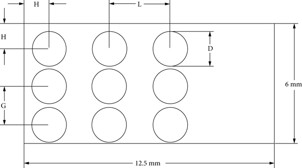
Geometrical modeling parameter.
The distance between the fiber’s center and the fiber diameter are most geometrically affecting parameters of the material hardness apart from the orientation of the fibers, so the distance between the fiber’s center and the fiber diameter is taken as varying parameters of the present work. The different

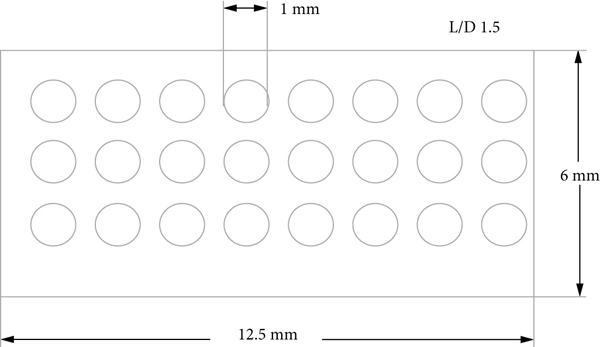
Models with different


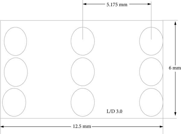

Models with different


2.2. Analysis Details
The finite element approach based ANSYS® package is employed in indentation analysis of natural fiber-reinforced composites. In order to mesh the above models, 8-noded 2D element (PLANE 183) is taken. The meshed model of

Meshed model of

Finite element model of
2.3. Validation of Present Model
The present finite element model is validated with Yanping Cao et al. [38] model, and the result shows a variation less than 1%. The indentation depth is given up to 1 mm in the present model. Figure 6 shows the indentation load versus indentation depth for the present model which shows the same behavior as Yanping Cao et al. [38] model.

Validation of present model with Yanping Cao et al. [38] model.
3. Results and Discussion
For the present indentation analysis, the most commonly using natural fibers and matrix are utilized which is given in Table 1 where the natural fiber-reinforced composite’s
Physio-mechanical properties of fibers and matrix.
3.1. Influence of Distance between Fiber Centers on Contact Parameters
The contact loads for every step are extracted from the analysis results.
3.1.1. Influence of Contact Load
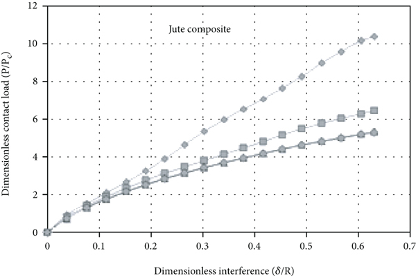
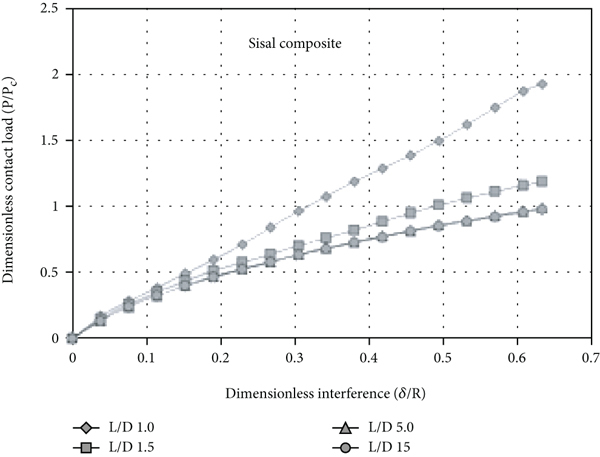
The response of contact load ratio against interference ratio for the

Contact load ratio for various


In Figure 7, as the dimensionless interference increases, the load-bearing capacity increases for all the fiber composites nonlinearly, but the trend looks similarly. The deviation among the load-carrying capacity increases as the interference ratio increases. For the same interference ratio, the jute fiber-based composite shows very high load-bearing capacity compared to all other composites. The sisal fiber-based composite shows very less load-carrying capacity, whereas the banana fiber-based composite behavior is intermediate so, for the increasing
3.1.2. Effect of Contact Area
The contact areas for every step are extracted from the analysis results. The contact area ratio against the interference ratio for the
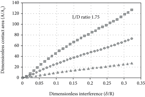
Variation of contact area ratio for various


From the Figure 8, as the dimensionless interference increases, the contact area ratio increases for all the fiber composites, and the deviation among them also increases. Compared to sisal fiber composite, the jute fiber composite shows five times high bearing area ratio, whereas the banana fiber-based composite shows two times high bearing area ratio. In each composite, for the same interference ratio, as the
3.1.3. Effect of
Ratio on Contact Load and Area
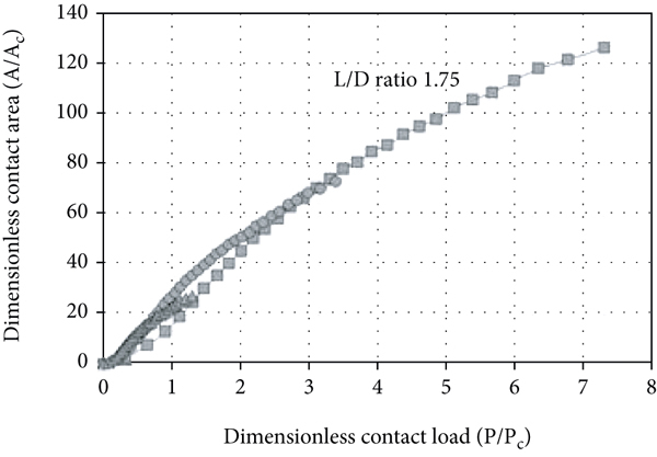
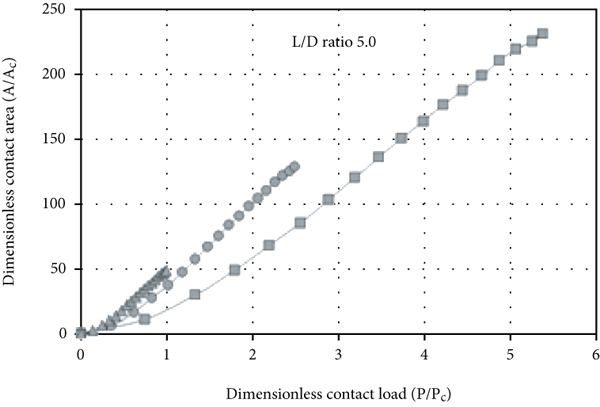
Figures 9(a) and 9(b) shown below show the response of contact area ratio against contact load ratio for various
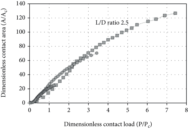
Response of contact area ratio vs contact load ratio for various


3.1.4. Effect of
Ratio on Contact Load and Area
Figure 10 shows the influence of

Response of contact area ratio vs contact load ratio for different composite.


The influence of
3.1.5. Effect of
Ratio and
Ratio on Von Mises Stress Distribution
The three modes of deformation of polypropylene such as elastic, elastic-plastic, and plastic deformations are extracted from the analysis results. The Von Mises stress plots of the three mode of deformation are shown in Figures 11(a)–11(c). The Von Mises stress distribution is used to identify the areas in which the equivalent stress is maximum and minimum and its distribution pattern and also it is used to predict failure of the material.

Von Mises stress plot for three modes of deformation of polypropylene matrix.


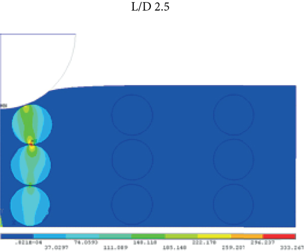
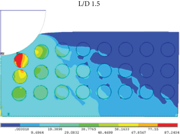
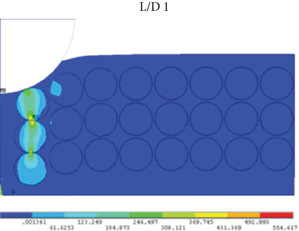
The resultant Von Mises stress plots for jute-polypropylene composite at
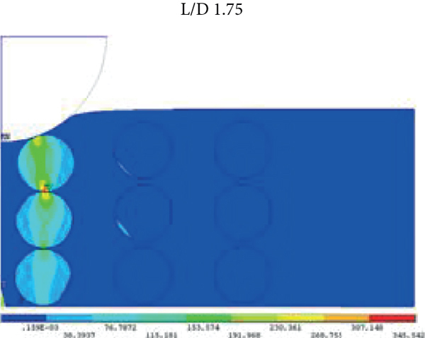
Von Mises stress plot for jute-polypropylene composite for various


Figures 13(a)–13(d) show the stress distribution in the banana-polypropylene composites of increasing

Von Mises stress plot for banana-polypropylene composite for various


When compared to jute and banana fiber-reinforced composites, the stress distribution in sisal-polypropylene composite is significant. The resultant Von Mises stress plots for sisal-polypropylene composite at

Von Mises stress plot for sisal-polypropylene composite for various

3.2. Influence of Fiber Diameter on Contact Parameters
The contact loads for every step are extracted from the analysis results by accounting the influence of fiber diameter.
3.2.1. Effect of Contact Load
The response of contact load ratio against the interference ratio for the
Response of contact load ratio vs interference ratio for various


As the interference ratio increases the contact load ratio increases for all fiber-reinforced composites. The load-bearing capacity of all the composites decreases with increase in
3.2.2. Effect of Contact Area
From the analysis results, the contact area for every step is calculated. The response of the contact area ratio against the interference ratio for the

Response of contact area ratio vs interference ratio for various


Response of contact area ratio vs contact load ratio for various


As the interference ratio increases, the contact area ratio increases nonlinearly for all fiber-reinforced composites. The jute fiber-reinforced composite shows large load-bearing area compared to all other fiber-reinforced composites. As the
3.2.3. Effect of
Ratio on Contact Area against Contact Load
As the contact load ratio increases, the contact area ratio also increases linearly, but on the other hand as the
3.2.4. Effect of
Ratio on Contact Load against Interference
The influence of the
In Figure 18, the load-bearing capacity is high for jute composite, for sisal composite is low and intermediate for banana composite, but as the dimensionless interference increases, the load-bearing capacity decreases for increasing
Response of contact load ratio vs interference ratio for various

In Figures 19(a)–19(c), for the high

Response of contact area ratio against contact load ratio for various


3.2.5. Effect of
Ratio on Von Mises Stress Distribution
The resultant Von Mises stress plots for jute-polypropylene composite at

Von Mises stress plot for jute-polypropylene composite for various


The resultant Von Mises stress plots for banana-polypropylene composite at

Von Mises stress plot for banana-polypropylene composite for various


The resultant Von Mises stress plots for sisal-polypropylene composite at
Von Mises stress plot for sisal-polypropylene composite for various


Empirical relations are developed for contact parameters with variables as dimensionless interference and ratio of distance between fiber centers to diameter of fiber:
4. Conclusion
Indentation analyses are carried on sisal-polypropylene, jute-polypropylene, and banana-polypropylene natural composites through finite element method. The results revealed that the neat polypropylene undergone three different modes of (elastic, elastoplastic, and full plastic) deformation regimes, but the indentation of the sisal-polypropylene, jute-polypropylene, and banana-polypropylene composites exposed only elastic deformation and stayed away from the elastic-plastic and plastic deformations.
As the distance between fiber centers increases, the contact load ratio increases nonlinearly for all composites. The load-carrying capacity of jute fiber composite is six times, and the bearing area ratio is five times greater than sisal fiber composite at maximum interference ratio. The impact of subsurface stress gets reduced as the distance between fiber centers increases. Compared to varying the distance between the fiber’s center, the variation in diameter of fiber influences significantly. After the
Generalized empirical relations are developed to appropriately calculate contact load, contact area with variables as interference ratio, and ratio of distance between the fiber centers and diameter of fiber.
Footnotes
Data Availability
The data are made available within this article.
Conflicts of Interest
The authors declare that they have no conflict of interest.