
Abstract
Tree multicast configuration of smart meters (SMs) can maintain the connectivity and meet the latency requirements for the Advanced Metering Infrastructure (AMI). However, such topology is extremely weak as any single failure suffices to break its connectivity. On the other hand, the impact of a SM node failure can be more or less significant: a noncut SM node will have a limited local impact compared to a cut SM node that will break the network connectivity. In this work, we design a highly connected tree with a set of backup links to minimize the weakness of tree topology of SMs. A topology repair scheme is proposed to address the impact of a SM node failure on the connectivity of the augmented tree network. It relies on a loop detection scheme to define the criticality of a SM node and specifically targets cut SM node by selecting backup parent SM to cover its children. Detailed algorithms to create such AMI tree and related theoretical and complexity analysis are provided with insightful simulation results: sufficient redundancy is provided to alleviate data loss at the cost of signaling overhead. It is however observed that biconnected tree provides the best compromise between the two entities.
1. Introduction
Advanced Metering Infrastructure (AMI) is a hierarchically heterogeneous communication infrastructure whose aim is to maintain the interaction between electrical power utility and power consumers. Home Area Network (HAN) is the low level of AMI whereby smart appliances (SA) connect within a short range star communication network with the smart meter (SM) that acts as the smart home gateway.
At the intermediate level, in the neighborhood area network (NAN), smart meters rely on each other to report their power demand to the utility [1]. The NAN is segmented in autonomous NAN Building Blocks (NANBBs) and smart homes connect within a tree network configuration of the SMs rooted at the dedicated router gateway (RG). The various RGs at the intermediate level connect in a full wireless mesh network and merge all the various autonomous NANBBs into an AMI Wireless Network (AWN) centered around the dedicated collector base station (CBS) at the substation (Figure 1).
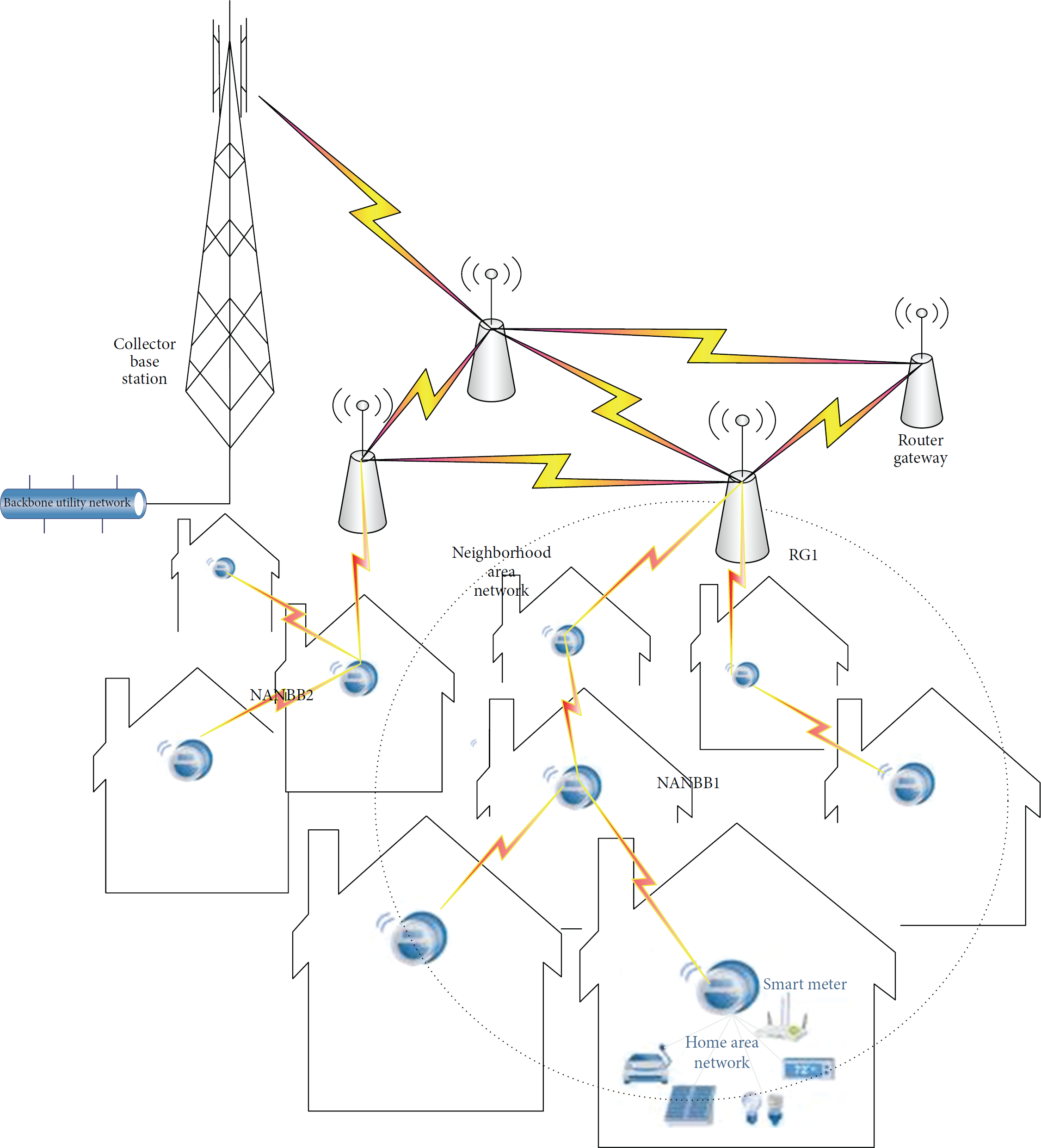
AMI Wireless Network (AWN).
In a WMN topology every node is connected to every other node in the network (Figure 2), so that a new node can be added to an active communication path to remediate another node or link failure without the need of an external action (self-healing and configuring). It is thus immune against single point of failure. Here, every node not only sends its own signals but also relays information from other nodes (for flooding or routing mechanism) which makes the topology very expensive as there are many redundant connections. Consequently, WMN is difficult to maintain and suffers from bandwidth waste as well as delay and signaling overhead due to aforementioned redundancy [2]. Almost 50% of the gross data rate has to be used for overhead to guarantee links stability and uninterrupted data transmission. In addition, another 50% of the available data rate has to be reserved for the backup path. As such, radios are sending the same data twice. Smart meters (SMs) are sensor-like devices that are limited in storage and computational capability and are not good candidates for mesh network structure compared to the RGs. WMN is thus unlikely to deliver the speed necessary to fulfill the latency requirement of AMI although it can maintain the connectivity as any SM node or link failure does occur [3–5].

Mesh-based NANBB network.
Tree multicast configuration of smart meters is appropriate to maintain a connected network topology and meet the latency requirement for the AMI. It is easy to set up and it is decent in terms of delay, signaling overhead, and bandwidth waste compared to its mesh counterpart. In order to further satisfy the delay constraint of AMI, hop-constrained or shallow trees may be established. However, such network topology is extremely weak as failure of any single node or link could cause the network to partition into separate blocks [2], which may lead to significant loss of data.
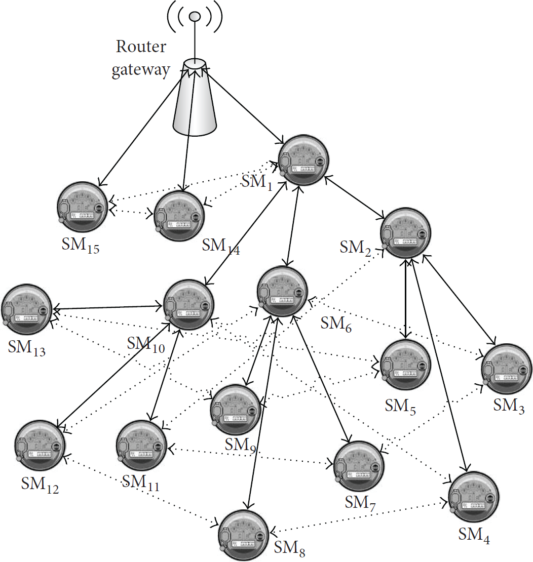
This prompts the design of a novel network architecture that merges the advantages of both tree and mesh topology to satisfy the latency requirement while providing a minimum redundancy to ease the connectivity recovery from link failure [6–9] (e.g., Figures 4 and 5). Furthermore, node failure can still have more or less significant impact on such augmented tree connectivity depending on its location: a leaf SM or noncut SM will have a local limited impact compared to a cut SM that will partition the network into disjoint blocks such that some SMs are not able to report to the RG. Such cut SM node is considered of significant criticality. For example, in Figure 9, the network remains connected after any of the leaf smart meters such as
Many existing research works on network link connectivity and reliability have focused on the cellular network backhaul augmentation which in the context of AMI corresponds to the data aggregator unit (i.e., Collection Base Station or CBS) interconnection. Dutta and Kubat in [10] propose the use of self-healing rings for the backbone network. In [11], Charnsripinyo and Tipper use a two-phase approach, one to determine the minimum cost network design to satisfy traffic demand and QoS and the other one to consider a problem of incremental network design for minimum cost network to augment the topology with backup link to the backhaul. On the node failure connectivity, existing research works on sensor networks take advantage of the node mobility to propose topology repair schemes in which nodes react to failure by relocating and isolating the failing node to maintain the network connectivity. In [12], Abbasi et al. rely on the view of a node in its neighborhood to design a recovery scheme that relocates the minimum number of nodes while ensuring conservation of path length between any pair of nodes. In [13, 14], predetermined criteria to involve any node in the connectivity recovery effort are maintained in a table for neighboring one- or two-hop node. All the aforementioned schemes rely on the node mobility. In AMI, SM nodes are not movable.
In this paper, we focus our work on the low level end-user's communication network, the neighborhood area network (NAN) reliability: an algorithm is designed to select a set of backup links to augment the NANBB tree based topology from 1-edge-connected tree to λ-edge-connected tree, where
In the AMI, SM nodes are not mobile and cannot relocate as proposed in previous works. To address the impact of a SM node failure on the connectivity of the augmented tree network, a proactive topology repair scheme is proposed. It relies on a loop detection scheme to define the criticality of a SM node and specifically targets the cut SM nodes by selecting a set of backup parents to all the immediate children SM nodes. These links come into action immediately after the cut SM fails such that the AMI network mutates and recovers the connectivity by isolating the failing critical SM node.
The rest of this paper is organized as follows. In Section 2, motivating examples are provided to illustrate the minimum redundancy and showcase the ease of connectivity recovery in biconnected and triconnected topologies from link failure. Section 3 studies the basic case of biconnected tree topology for NANBB. A depth first search based algorithm is proposed to solve the biconnected tree augmentation. Section 4 enumerates major change to the DFS algorithm to accommodate the λ-connected tree algorithm to suit higher level of connectivity. Section 5 presents the topology repair scheme to address the impact of the node failure and connectivity recovery in augmented tree network. In Section 6, a study is proposed to evaluate the complexity of the algorithm in terms of the size of the network and the target connectivity. In Section 7, IEEE 802.11 MAC handshake protocol is employed as basis to simulate and assess the effectiveness of the augmented tree topology in terms of signaling overhead and data loss. Section 8 summarizes the work.
2. Link Failure Connectivity Recovery: Motivating Examples
In this section, we focus on studying two basic augmented NANBB tree based topologies. Specifically we describe and outline the reliability improvement of augmented tree based NANBB for
Connectivity is a predominant concept in a communication network; it refers to the network ability to sustain its full operation despite link failure [17]. For a connected NANBB network, its spanning tree is a configuration through which all the SMs are connected with

Tree based NANBB network (degree 3).

Double link failures recovery in a biconnected NANBB.
Triple link failures recovery in a triconnected NANBB.
The goal of this work is to mitigate the weakness of the NANBB spanning tree based communication topology by assigning backup links to thwart against single point of failure and increase its reliability [18]. This may be measured by the probability that the network remains connected despite link failure; that is, any SM somehow remains capable of transmitting its power demand to the RG under link failure, provided that other SMs are operative.
Consider the two augmented tree based NANBBs: biconnected (Figure 4) and triconnected (Figure 5). In the biconnected tree (Figure 4), each SM maintains at least two disjoint paths to the RG. Upon failure of any single communication link (red star), the adjacent backup communication links take over to maintain the connectivity of the corresponding SMs (
Figure 5 shows three-failure recovery for
3. Link Failure Connectivity Recovery: Biconnected Tree
In this paper, we make the following assumptions: (1) only one-node SM or communication link failure occurs at a time in the network, the rationale being that multiple simultaneous failures are less likely; (2) a SM node would transmit at its maximum power to increase the chance of being in range with multiple neighbors; (3) the wireless nature of the medium prompts considering link cost generally specified in terms of delay, packet loss rate, bit error rate, guaranteed bit rate, and so on. On the other hand, undesirable connectivity augmentation due to RF signal propagation is worth investigating; communication security scheme involving key distribution and management is a good candidate solution [2]: only SM nodes sharing a secret key can communicate such that radio signals from other nodes in range are simply ignored.
3.1. Problem Formulation and Definitions
A NANBB communication network can be represented by a graph
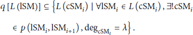
The router gateway (RG) is the root to which any SM directs its data. Given a smart meter
The tree based NANBB connection reliability problem can be formulated as identifying the minimum set of links to be considered as candidate backup link to a backup parent SM. In other words, the goal is to find additional backup SM through which each individual SM can rely on for connecting to the tree root RG as its original parent SM is out of reach due to link failure. At the detection of the failure, it could take step to activate the backup link and remain connected [15].
The connectivity augmentation in a NANBB tree network
Let
The following definitions for NANBB tree network topology are introduced:
A leaf smart meter denoted as A cut smart meter A stem smart meter
From the motivating example described above (Section 2) the following significant observations are made:
Leaf smart meters Connectivity augmentation requires at least
The following categories [15] describe the set from which a backup SM derives:
Uncle: the set of the backup SMs contains the sibling of the parent SM. The root RG has no brother and, as such, its children SMs have no uncle and thus no backup SM either. Cousin: this set of backup SMs is made of the uncle's children SMs. Here also, the root has no brother. This makes it impossible to the root's children to have backup SM as well.
3.2. NANBB Biconnected Tree Link Augmentation
In this section, we present an algorithm for solving communication link augmentation based on the observation in Section 2 and algorithms in [20]. Prior to that, we describe the depth first search (DFS) algorithm to derive the NANBB tree topology. Breath First Search (BFS) is another search scheme where each node is visited and numbered with access to all of its neighbors at the same time; the neighbors are likewise visited next all together in turn, and so on [21, 22]. In both cases, the root RG is first located where the search starts. They all have similar performance cost in terms of time and space. However, the nodes order produced by the DFS is more appropriate for our scheme in Section 3.2.2 that we survey in [20].
3.2.1. Depth First Search (DFS) Algorithm
The root is chosen and its immediate rightmost child SM is explored; the search progresses recursively until reaching a set goal or hitting the last rightmost SM node. From there, the search backtracks and resumes at the last rightmost descendant SM not completely explored [23]. Here each SM is required to have at most λ children (i.e.,
Data Structures
State: a SM is sequentially unvisited, discovered, visited, and finished when the DFS withdraws.
An appropriate description of a DFS for a NANBB network is in terms of the spanning tree of SMs as the search ends. Its mechanism in a NANBB perspective is based on setting and getting the labels of SMs and communication links of the spanning tree.
3.2.2. Algorithm: NANBB Biconnected Tree Network
Here, the problem is to find the smallest set of links which in addition to the NANBB spanning tree communication network makes it biconnected so as no single link failure can disconnect any single SM (Figure 4).
Initially the algorithm calls the NANBB network and identifies its root which in this case is the data aggregator unit RG. The NANBB tree network topology is issued resulting from the DFS (Section 3.2.1). The NANBB network is a simple tree that spans all the SMs. A single communication link failure suffices to break the network connectivity, whereas a single SM failure results in the segmentation of the network in a number equal to its degree, whichever case prevents a set of SMs from communicating with the root RG (Figures 3 and 7).
Consider

For example, in the NANBB tree (Figure 3), the set of leaves
Upon augmentation of the first partition

The recursive process proceeds following a rightmost DFS technique until the entire network reduces to a single SM (i.e., RG).
4. Link Failure Connectivity Recovery: λ-Augmented Tree
In this section, we study the NANBB tree λ-augmentation based on the requirement that the source NANBB network is a full mesh of at least degree λ (i.e., each node including the RG in the NANBB mesh has at least λ disjoint communication paths to any other node) and we enumerate the different changes to enhance Algorithms 1 and 2.
(1) (2) (3) Mark label (4) Mark label (5) Select RG, DFS's root. (6) Mark label RG: visited (7) (8) (9) Select (10) (11) (12) Mark label (13) Add (14) Mark label (15) Mark label (16) Add (17) (18) Set the label of (19) (20) (21)
(1) (2) (3) (4) Mark (5) Mark (6) (7) Compute (8) Select rightmost (9) (10) Compute (11) (12) Add (13) Mark (14) Mark (15) (16) (17) Compute (18) (19) Compute weight of (20) Mark (21) Add least weighted (22) Mark (23) Identify biconnected subtree (24) Contract (25) Update (26) (27) Add edge (28) Mark (29) Update (30)
4.1. DFS Algorithm
DFS Algorithm 1 has to be modified to output a NANBB tree of degree at most
Specifically, in its line (19), DFS Algorithm 1 has to be changed into
Figure 7 shows the example DFS output for
4.2. NANBB λ-Connected Tree Communication Network
Algorithm 2 is upgraded into Algorithm 3 to accommodate higher degree tree topology (i.e., Figure 7 for
(1) (2) (3) (4) Mark (5) Mark (6) (7) Compute (8) Select rightmost (9) (10) Compute (11) (12) (13) (14) Add (15) Mark (16) Mark (17) (18) (19) Compute (20) (21) Compute weight (22) Mark (23) Add the least weighted (24) Mark (25) Add (26) Identify λ-connected subtree (27) Contract (28) Update (29) (30) Add edge (31) Mark (32) Update (33)
The following changes can be seen in Algorithm 3 NANBB λ-connected tree network:
In line (7), the partition of leaf SM is done with consideration of λ for the degree of Lines (11) and (12) are added to identify the incident link in the spanning tree. Line (13) is added to ensure up to Lines (28) and (29) are used to create and identify the rightmost λ-connected subtree.
5. SM Node Failure Connectivity Recovery
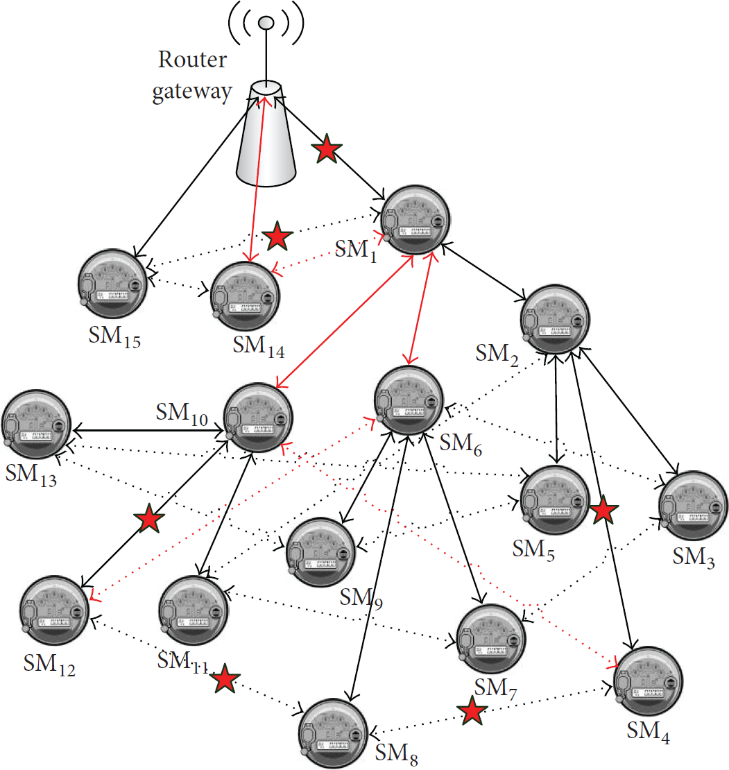
The scheme developed above can certainly generate multiple disjoint paths to mitigate the weakness of the tree topology and improve the robustness of AMI. However, these paths are seldomly node disjoint as they cross over at numerous SM nodes whose failure can more or less significantly affect the connectivity of such augmented tree network: a leaf SM or noncut SM will have a local limited impact compared to a cut SM that will partition the network into disjoint blocks such that some SMs are not able to report to the RG. Such cut SM nodes are critical for the network connectivity. For example, in Figure 9, the network remains connected after any of the leaf smart meters such as
In this section, we describe a proactive topology repair scheme to reconfigure the augmented tree network in response to SM node failure. It mostly targets the critical nodes as previously mentioned: a loop detection mechanism is used to define a critical SM node (e.g.,
Each SM node in addition to the routing table maintains a loop detection table to record the packets forwarding activities. The node can use the packet identifier to detect a returning packet and conclude on the existence of a loop.
5.1. Loop Detection Mechanism
The loop detection mechanism as depicted in Figure 9 mimics the depth first search algorithm. In this mechanism, the purpose is not to route the packet to the best candidate next hop in the routing table, but instead to check each next hop to determine if it belongs to a loop.
When a node creates a packet that it wants to use for loop detection, it appends its address to a sequence number to create an identifier that it stores in its loop detection table. The identifier is unique and can be used to trace the packet in the entire network. The address of the next node is also stored in the table. However, the destination field of such packet is always loaded with the router gateway (RG) address.
The loop detection is a per node scheme (i.e., each node initiates the detection and determines if it is a choking point). After a node has created the packet as previously mentioned, it forwards it to its rightmost child in the augmented tree NANBB network, where the packet follows a normal forwarding mechanism per the underlying routing protocol. Hence, it is assumed that there exists a control plane that continuously finds and fills up the
A packet loss can occur during the loop detection scheme in which case the acknowledgment message is not received back at the forwarding node. After a specified waiting time, the node proceeds to reroute the packet by forwarding it to the next child in the augmented tree.
The illustration of loop detection for node Node Node Node Node Node All the one-hop SM nodes in the neighborhood update their loop table to include the information on the criticality of node
5.2. SM Node Failure Detection
SM nodes periodically broadcast heartbeat messages to neighbors to notify that they are up and operational and as well report changes to their one-hop neighbors. By means of missing heartbeat messages, active SM nodes can conclude the failure of a neighbor.
At the detection of such failure, the one-hop neighbors of the failing SM node would determine the impact, that is, whether the failing node is critical to network connectivity. They will do so by means of lookup in their loop table to see if the failing SM node is a choking point as previously described. The children of such critical SM node will react to such failure by redirecting their communication to the backup SM parent node, thus isolating the failing cut SM node (like
6. Algorithm Computational Complexity
The above scheme follows the procedure of the depth first search (DFS) algorithm which is a search that sequentially explores the tree network in a descendant fashion. That is, each SM is visited by the algorithm and at each step all the incident communication links to a given cut smart meter ( n nodes are visited.
Consider
The total combined visitation for both Algorithms 1 and 3 will be
7. Simulation Results
In this section, we assess the performance of the proposed scheme. The analysis is twofold. Firstly, we use the IEEE 802.11 MAC handshake protocol to compare the efficiency of mesh, tree, and augmented tree NANBB network configuration in terms of signaling overhead. We also use Matlab simulation to provide a comparative representation of average data loss due to communication link failure in those NANBB network configurations.
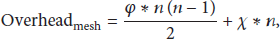
Assuming the handshake request as well as reply packets of size 20 bytes each and also given a 36% successful rate for the aloha handshake protocol, the signaling overhead for a successful handshake can be estimated to
The NANBB tree communication network augmentation is mostly about covering each and every leaf smart meter with up to (


Backup SM category in a biconnected tree NANBB.

Tree based NANBB network (degree 4).
Triconnected tree NANBB.

Critical node, loop detection in biconnected tree NANBB.

Critical node, failure recovery in biconnected tree NANBB.
Figures 11, 12, and 13 show signaling overhead comparison with regard to different size of NANBB and connectivity level. We have the following observations:
Regardless of the size of the NANBB network, the signaling overhead difference between the tree and the biconnected tree is insignificant; in fact it is less than 5%. The signaling overhead increases reasonably for connectivity up to 3 and as connectivity approaches 4 it increases significantly to almost 80% for

Signaling overhead comparison for

Signaling overhead comparison for

Signaling overhead comparison for
The simulation result in Figure 14 clearly shows the extremely poor performance of the full mesh NANBB when it comes to signaling overhead. In fact, the overhead increases exponentially with the number of smart meters.

Mesh, biconnected tree, and tree overhead comparison.
On the other hand, the NANBB tree topology shows a very steady slow overhead increase with the number of SMs. It clearly outperforms its mesh counterpart as it barely approaches the 5% ratio at 100-SM population. The performance of the biconnected tree NANBB topology lies in between with a strong similarity to that of the tree. It barely exceeds 50% as the number of SMs grows to a hundred.
For the data loss, the comparative average packet loss for 1-, 2-, and 3-communication link failure is shown in Figure 15. It can be noticed that, in the case of the biconnected tree NANBB topology, there is no data loss until 2 communication links fail all together whereas, for the spanning tree, data loss occurs as soon as a single communication link fails. The robustness of the biconnected tree remains significantly prevalent compared to spanning tree as the number of link failures increases reasonably to 3.

Tree, augmented tree data loss comparison.
8. Conclusions
A framework for tree based communication network augmentation is proposed to improve the robustness of data collection in neighborhood area network building blocks of AMI. It merges the virtues of mesh as well as tree based network topologies: signaling overhead increases reasonably not exceeding 15% for connectivity up to 3. It grows significantly to almost 80% as connectivity approaches 5 (Figure 13). Sufficient redundancy is also provided to mitigate the tree single point of failure such that no data loss occurs until λ adjacent links fail simultaneously. Thus, with the connectivity, while the data loss decreases on one hand, the signaling overhead increases on the other hand, which prompts the search for a trade-off topology to fulfill all together the real-time and availability requirements of AMI. Biconnected tree NANBB (
A proactive topology repair scheme is proposed to address the impact of SM node failure on the augmented tree network connectivity. It relies on a loop detection scheme (Figure 9) to define the criticality of a SM node and specifically targets the cut SM node by selecting a set of supplemental parents as backup to all its children SM nodes. These links come into action immediately after the cut SM fails. By this means, the topology mutates and the AMI network recovers the connectivity by isolating the failing critical SM node (Figure 10).
The proposed scheme however lacks in root redundancy so that any faulty RG will disconnect the corresponding NANBB. Fortunately, many existing research works such as [11] on network reliability in the context of AMI have focused on the cellular network backhaul augmentation that corresponds to the data aggregator unit (i.e., RG) interconnection.
Footnotes
Disclosure
The US Government is authorized to reproduce and distribute reprints for governmental purposes notwithstanding any copyright notation thereon. The views and conclusions contained herein are those of the authors and should not be interpreted as necessarily representing the official policies or endorsements, either expressed or implied, of the NSF, DOE, or the Office of the Assistant Secretary of Defense for Research and Engineering (OASD (R&E)) or the US Government.
Competing Interests
The authors declare that there is no conflict of interests regarding the publication of this paper.
Acknowledgments
The first author is supported by the HBGI Scholarship. This research work is supported in part by the US National Science Foundation (NSF 1238859), the US DOE NNSA Sam P. Massie Chair Program, and the Office of the Assistant Secretary of Defense for Research and Engineering (OASD (R&E)) under Agreement no. FA8750-15-2-0119.