
Abstract
In severe disaster environments, data-gathering wireless sensor networks possibly suffer from spatial node failure due to external factors such as land slide and river overflow. In order to enhance tolerance to spatial node failure, this paper proposes not only a multipath data gathering protocol called “Side Trip (ST)” scheme but also an improved version of ST scheme called “Side Trip with Network Coding (STNC)” scheme. In the ST scheme, a node establishes a secondary path which passes through nodes almost the same hop count away from the sink in order to spatially separate the path from the primary path and enhance spatial node-failure tolerance. In the STNC scheme, redundant packets from different source nodes are network-coded into an encoded packet in order to reduce the number of redundant packets and the impact on the system lifetime. We compare the ST scheme, STNC scheme, and two existing multipath protocols (i.e., H-SPREAD (Hybrid-Secure Protocol for REliable dAta Delivery) scheme and SMRP (Subbranch Multipath Routing Protocol) scheme) by means of a self-developed simulator. Simulation results show that STNC scheme and ST scheme enhance tolerance to node-failure compared to H-SPREAD scheme and SMRP scheme with no significant impact on system lifetime.
1. Introduction
A wireless sensor network (WSN) that consists of many sensor nodes should enable us to collect sensed data over a wide area. Applications of WSNs include remote monitoring and smart space. In this paper, we consider data-gathering WSNs which consist of battery-operated sensor nodes; they periodically send sensed data to a single sink node via multihop communication. In such WSNs, system lifetime strongly depends on the remaining battery level of certain nodes, especially those one hop away from the sink node.
In case of severe disasters such as landslide and flooding, node failure may possibly exhibit a strong spatial correlation in a sense that nodes in a certain area are disabled at the same time [1,2]. In this paper, we call this kind of failure “primary failure.” Primary failure may cause “secondary failure,” which is the fact that other nodes cannot transmit sensed data to the sink if their paths to the sink node traverse those disabled by the primary disaster. In case of disasters such as landslide and flooding, it is deemed necessary to know which area is stricken as soon as possible. Thus, depending on a kind of applications, it is important to distinguish between an area of primary failure and that of secondary failure. In this paper, this issue is addressed.
A way to enhance node failure tolerance is for each node to establish multiple paths to the sink node and to transmit duplicate packets over them [3,4]. However, if the multiple paths are not sufficiently separated spatially from each other, they may traverse an area of primary failure. As a result, the node suffers from secondary failure. Further, more duplicate packets consume more energy in relay nodes, so that system lifetime is shortened. H-SPREAD (Hybrid-Secure Protocol for REliable dAta Delivery) scheme [3] and SMRP (Subbranch Multipath Routing Protocol) scheme [4], which are existing multipath schemes, suffer these problems.
The aim of this study is to achieve as high a tolerance to geographically correlated node failure, that is, spatial node failure, as possible without shortening the system lifetime significantly. To do so, we try to detour a secondary path far from the primary path and suppress redundant packets by leveraging interflow network coding (NC). Here, we call nodes n hops away from the sink the “nth-level nodes.” Generally speaking, the first-level nodes, which neighbor the sink, tend to relay more packets than the others in data-gathering WSNs. Further, when all first-level nodes exhaust their batteries, the sink node cannot collect data anymore regardless of node level. Therefore, system lifetime mainly depends on the battery level of first-level nodes. In other words, higher-level nodes do not affect system lifetime significantly.
Considering the above, we propose a multipath scheme, called “Side Trip (ST)” scheme. In ST scheme, a source node sends original packets over lower-level nodes toward the sink. We call this the “collection phase.” In the phase called “Side Trip (ST) phase,” the source node sends duplicate packets, that is, redundant packets, far from itself over the nodes of the same level. (How many hops they are relayed over and how to transfer packet to a node far from a source node are shown in Section3.) After ST phase finishes, the redundant packets are diverted to lower-level nodes, that is, toward the sink node, in the following collection phase. The resultant detour path can be expected to be spatially separated from the path carrying the original packets.
Further, we propose an improved version of ST scheme, called “Side Trip with Network Coding (STNC)” scheme, which utilizes interflow network coding in order to reduce the amount of redundant packets. Network coding (NC) has been studied as an in-network coding approach to enhance throughput, robustness, and security [5–7]. In STNC scheme, in the collection phase, two or more redundant packets are encoded by means of XOR (Exclusive OR) operation into an encoded packet if rules are satisfied, so that the number of redundant packets can be reduced. This mitigates the negative impact of redundant packets on system lifetime. The rules are explained in Section3.
Nodes consume energy when transmitting, receiving, and overhearing packets [8]. In ST scheme and STNC scheme, detouring the redundant packets in ST phase essentially increases the number of packet transmissions. This also increases unexpected overhearing unless some measure is taken. In this paper, we also propose node-state scheduling in which some nodes are set to sleep occasionally to reduce unexpected overhearing.
The rest of paper is organized as follows: Section2 briefly explains H-SPREAD scheme and SMRP scheme as existing multipath schemes. Section3 presents the details of our proposed schemes, ST scheme and STNC scheme, and proposed node-state scheduling. Section4 shows our simulation results. Finally, Section5 concludes this paper.
2. Related Works
In this section, we introduce H-SPREAD scheme [3] and SMRP scheme [4] as existing multipath schemes for data-gathering WSNs.
2.1. H-SPREAD
In H-SPREAD scheme, almost all nodes can discover multiple node-disjoint paths to the sink node. At first, the sink node broadcasts a path information message to the network. When a sensor node resends a received message, it appends its node identifier (ID) to the message. Thus, a path information message includes a path to the sink. If a sensor node receives a path information message that includes a new path that is disjoint to known ones, the sensor node remembers the newly received path and rebroadcasts the path information message after appending its node ID. Otherwise, the sensor node discards the message. After the above actions are repeated, almost all nodes will have multiple node-disjoint paths, and this feature is advantageous. Each sensor node chooses the first minimum-hop path as the primary path and the second minimum-hop path as the secondary path. As a result, both the paths tend to be spatially close, which weakens resistance to spatial node failure. Since a path information message includes a series of node IDs, it tends to be long. Further, path information messages are rebroadcasted many times. Thus, H-SPREAD scheme has large overheads.
2.2. SMRP
SMRP scheme aims to reduce the overhead at the cost of lower certainty of finding multipaths compared to H-SPREAD scheme. In SMRP scheme, it is assumed that each first-level node is power-supplied via feed line or it is easy to exchange the batteries since the first-level nodes are set close to the sink node. Based on this optimistic assumption, subtrees rooted at second-level nodes are constructed. At first, a sink node broadcasts a path initialization message which includes hop-count field, sender node ID field, and tag field to distinguish subtree. If a sensor node receives a path initialization message for the first time, it rebroadcasts the message after incrementing the hop-count field entry. At this time, if the sensor node notices that it is a second-level node, it fills the tag field with its node ID as the root of a subtree. A third- or higher-level node can know which subtree it belongs to from the first received path initialization message. A sensor node also learns the sender node of the first received path initialization message as the next node toward the sink. The resultant path is regarded as the primary path in the SMRP scheme. A second- or higher-level node may happen to find secondary paths if successively received initialization messages include tags different from its own tag. Since the sender of the message belongs to a different subtree, it is the next hop toward the sink on a path different from the primary path, that is, secondary path. Sensor nodes, however, cannot always discover secondary paths since they might not receive any initialization message with a tag different from their own. Since each sensor node rebroadcasts a path initialization message only once in the SMRP scheme, its overhead is less than that of the H-SPREAD scheme, which is advantageous. On the other hand, the primary path and the secondary path could share the same first-level node and they also tend to be spatially close, which weakens resistance to spatial node failure.
3. Proposed Schemes
In this section, first, we define the network model. Next, we explain the details of our proposed schemes, “Side Trip (ST)” scheme and “Side Trip with Network Coding (STNC)” scheme. Finally, we introduce a node-state scheduling for ST(NC) scheme.
3.1. Network Model
We consider data-gathering WSNs consist of one sink node which is placed at the center of area and sensor nodes which are placed at a density ρ and maximum level is

Data-gathering wireless sensor networks.
3.2. Side Trip with Network Coding
In the ST(NC) scheme, a sensor node sends an original packet via a primary path and a duplicate packet via a detour path, that is, a secondary path. Note that the first-level nodes do not issue any duplicate packets. Primary paths are constructed at the beginning of the system operation in a certain period, which we call “initialization phase.” This phase is also executed periodically in order to refresh the primary paths. As the primary paths, ST(NC) scheme constructs subtrees rooted at first-level nodes according to almost the same procedure as used by the SMRP scheme. The difference is that the second-level nodes fill the tag field of initialization messages in SMRP scheme while the first-level nodes do so in the ST(NC) scheme. In the ST(NC) scheme, a sensor node uses its subtree as the primary path as per the SMRP scheme.
After initialization phase, sensed data packets are collected from all sensor nodes to the sink node cyclically. Each collection is called “cycle” hereafter. A cycle is composed of “Side Trip (ST) phase” and “collection phase” as explained in Section3.3.
The aim of ST phase is to convey a redundant packet far away from its primary path. For this sake, the redundant packet is relayed via nodes which are on almost the same level as its source sensor node. That is, the redundant packet is moving in a circumferential direction around the sink node. This transfer is called “Side Trip.” ST is interrupted at every certain hop count. If the redundant packet stops at a node with a different tag from its source node, ST ends because its primary path and secondary path become node-disjoint. Otherwise, ST restarts. In this regard, however, the total number of hops in ST phase is limited up to “Side Trip Time to Live (ST-TTL)” to refrain from affecting the system lifetime as explained in Section3.2.2. In ST phase, it is necessary to prevent the redundant packet from looping back. For this sake, each node has “Side Trip ID (ST-ID),” which is determined in initialization phase. Each node chooses the next hop of ST according to its ST-ID and neighboring nodes' ST-IDs. This mechanism is called “Side Trip stairs,” as explained in Sections3.2.3 and3.2.4.
In the collection phase, original packets and redundant packets are relayed to lower-level nodes toward the sink along the primary path of current relay node. As a result, the secondary path of a redundant packet is composed of the part found in ST phase and the primary path of the relay node where the redundant packet ended ST. Therefore, the original packet and the redundant packet are expected to be conveyed over spatially separated node-disjoint paths. As mentioned above, in the collection phase, original packets as well as redundant packets are relayed toward the sink. At this time, NC operation is executed in STNC scheme. More precisely, if a sensor node happens to have two or more redundant packets or encoded packets which have different tags and the nodes tag each other, it encodes them into a single encoded packet by means of XOR operation. Hence, the resultant encoded packet has two or more tags. Therefore, the maximum number of data which are included in one encoded packet is the number that is one smaller than the number of kinds of tags. Note that this NC operation is not applied to the original packets. If an original packet is lost, it can be recovered at the sink from its corresponding encoded packet and the other original packet. Then, packets which are transmitted in collection phase have the following information:
sender ID, source node ID(s), source node tag(s), sequence number of data, data.
3.2.1. Side Trip Layer
In ST phase, redundant packets are transferred in a circumferential direction around the sink node. At this time, ST should be done in an interleaved manner to reduce interference among nodes with adjacent level as much as possible. On the other hand, a node does not always have a next neighbor node with the same level. Then, a group of nodes make a “Side Trip layer (STL),” and nodes construct the layer structure as shown in Figure2, where layer width is two. That is, the ith STL consists of the nodes with the

Example of Side Trip layer where the layer width is two.
3.2.2. Side Trip Time to Live
As mentioned in Section1, the first-level nodes are burdened by having to relay packets of all higher-level nodes in a data-gathering WSN. On the other hand, the higher-level nodes have less burden. Using this property, redundant packets are detoured in Side Trip layers in ST(NC) scheme. In ST phase, the maximum number of hops is limited such that the second- or higher-level nodes do not transmit more packets than the first-level nodes. The residual number of hops is called “Side Trip Time to Live (ST-TTL).” Its value is included in the redundant packet header and decremented every time the redundant packet is relayed. The redundant packet is discarded if its ST-TTL reaches zero. In what follows, how to estimate the initial value of ST-TTL is explained.
At first, we try to estimate the number of packets sent by a certain level node to a one-level-lower node on average. Here we call the


Next, we try to estimate the number of packets sent among the nodes of the same lth level. Let

In the case where the layer width is greater than two, nodes use
3.2.3. Side Trip Stairs
The mechanism “Side Trip stairs” aims to transmit redundant packets in one direction in a Side Trip layer. The mechanism utilizes “Side Trip ID (ST-ID).” Figure3 shows an example of Side Trip stairs. In this figure, small circles denote nodes in a certain layer, and each number denotes an ST-ID of each node. How to determine ST-ID will be explained later. ST-ID takes a nonnegative integer in a range, say,
An example of Side Trip stairs.
Next, let us explain the procedure to determine ST-ID. Each node is involved in the procedure after obtaining its layer level in initialization phase. The procedure is initiated by nodes called “starters” which satisfy with the following conditions:
The node has a neighbor node whose tag is different from its own tag. The node has a larger tag than the neighboring nodes. sender ID, Side Trip ID, tag of starter, tag of starter's neighbor. Side Trip ID, tag of starter, tag of starter's neighbor.
For this sake, neighboring nodes exchange tag with each other. At first, each starter broadcasts an ST-ID propagation packet, which includes the following information:
Sender ID is the node ID of the last sender of the packet, and it is updated every time rebroadcasted. If a starter has neighbors with different tags, “the tag of starter's neighbor” is set to the largest tag among them. All nodes store the following information:
When initiating the ST-ID propagation packet, each starter sets the value of ST-ID of the packet to zero and also stores its value in itself. The other nodes initially set (i.e., store) ST-ID, “tag of starter,” and “tag of starter's neighbor,” to default values, say,
When receiving an ST-ID propagation packet, the nodes overwrite stored information and rebroadcast the packet if one of the following rules is satisfied:
The node's ST-ID is default value. “Tag of starter” of the received ST-ID propagation packet is greater than “tag of starter” which the node stores. “Tag of starter” of the received ST-ID propagation packet is equal to “tag of starter” which the node stores, and “tag of starter's neighbor” of the received ST-ID propagation packet is greater than “tag of starter's neighbor” which the node stores.
However, the nodes do not overwrite stored information and rebroadcast the packet if the sender's node ID is equal to “tag of starter,” and “tag of starter's neighbor” is equal to its own node ID. This prevents the ST-ID propagation packet from bouncing back. As a result, ST-ID propagation packets are expected to propagate in one direction. Before rebroadcasting the packet, the node updates its “tag of starter” and “tag of starter's neighbor” by those in the packet. It also increments the ST-ID field of the packet by one modulo
If every node performs the above procedure simultaneously, their transmissions interfere with each other. To mitigate the interference and reduce power consumption, the initialization phase of ST-ID is divided into two slots. In the first slot (resp., the second), the nodes with even (resp., odd) layer ID perform the node with odd (resp., even) layer ID sleep. Since the first-level nodes do not need ST-ID, they sleep immediately after getting level. Thus, the procedure does not affect the system lifetime significantly.
3.2.4. Side Trip Stair Count
In ST phase, redundant packets are conveyed far away from their source node. It is desirable for the distance to be distributed randomly quarter through half away around the sink node rather than constant. This is because STNC scheme encodes packets with different tags as explained in Section3.2. As a result of the initialization of ST-IDs, nodes with different ST-IDs are expected at least apart by r, which is the transmission range. Then, the round distance can be regarded as

In ST phase, each source node calculates STSC and set into the redundant packets. Every time the packet is relayed, the value of STSC is decremented. If STSC reaches zero, ST finishes. As mentioned earlier in this section, if a redundant packet finishes ST on any node with the same tag, ST is continued as long as the total hop count is less than or equal to the upper limit
3.2.5. Example
Here let us explain STNC scheme using Figure4. In this figure, node shape represents tag kind. Suppose that STSC is set to 3 and all ST-IDs of nodes are different, so that redundant packet

Example of subtrees constructed by STNC scheme.
3.3. Node-State Scheduling
One of the effective ways to reduce power consumption is to make sensor nodes sleep for as long as possible. Further, nodes consume energy when transmitting, receiving, and overhearing packets [8]. In ST scheme and STNC scheme, the detouring of redundant packets in ST phase basically increases the number of packet transmissions as well as the unexpected overhearing events unless some countermeasure is taken. In this section, we explain slot-based node-state scheduling for ST(NC) scheme. All nodes perform scheduling synchronously, so that nodes which need not to transmit or receive any packets are put to sleep to reduce their active time as well as unexpected overhearing.
In this scheduling approach, as shown in Figure5, time is divided into an infinite number of equal period cycles which consist of two phases: ST phase and collection phase. ST phase is divided into two slots, while collection phase is divided into at least

Slot-based node-state scheduling.
In ST phase, when the lth-level nodes awake to issue and relay redundant packets, both the

Slot action state in Side Trip phase.

In collection phase, each node transmits packets (Tx), receives packets (Rx), or sleeps according to scheduled state. Consequently, since different level nodes to transmit packets are three levels away from each other, interference at receiving nodes is mitigated. To do so, the nodes are divided into three groups based on the remainder of their level when divided by three, and each group behaves as shown in Table2. The sequence of three slots for transmission, reception, and sleep state needs to be repeated until all packets are collected by the sink node or a specified time has passed. In STNC scheme, nodes encode redundant packets which are satisfied with rules when slot state becomes Tx. In each Tx slot, the nodes without any packets to be transmitted can sleep. In our simulations shown in Section4, however, such nodes stay awake in the same manner as in existing schemes in order to restrict the advantage of ST(NC). On the other hand, in each Rx slot, the leaf nodes, which have no upper level neighbor nodes, need not to receive any packets. Therefore, they sleep in Rx slot.
Slot action state in collection phase.

Shorter slot restricts data collection delay. Too short slot, however, degrades the effect of NC. This is because each node has less redundant packets in a slot so that they cannot be encoded together. Therefore slot duration for collection phase should be set carefully according to scenarios. The higher-level nodes finish transmitting and relaying packets earlier, and it is inefficient to leave the lower nodes awake with nothing to do.
If a node does not need to relay any packet from children and has no packet to send, it falls to sleep to reduce its active time. To do so, a node notifies its parent that it will sleep using a control packet called “sleep notification message.” Consequently, a parent node can enter sleep if it is notified from all children and has no packet to transmit. Finally, note that, in STNC scheme, the nodes in transmission state encode redundant packets with different tags, if any, before transmission. In each slot, nodes also transmit “sleep notification message” when they finish transmitting packets in the slot.
4. Performance Evaluation
In this section, we compare ST scheme and STNC scheme with the SMRP scheme, H-SPREAD scheme, and single path (SP) scheme using a self-developed simulator; the metrics are system lifetime, spatial node failure tolerance, and delay until all of the data are collected. Here, SP scheme is the scheme where each source uses a single path like a primary path of ST(NC) scheme. We consider two scenarios: the case of no node failure and the case of spatial node failure. In case of no node failure, we regard the period yielding 95% collection as system lifetime. Here, the collection ratio in a cycle is defined as the ratio of the number of data packets collected by the sink node to the number of all the sensor nodes. On the other hand, in the case of spatial node failure, we evaluate the failure avoidance ratio (FAR), which is defined below as (9), in terms of the spatial node failure tolerance. As mentioned in Section1, a secondary disaster node is a node whose primary path is broken due to primary disaster. The failure avoidance ratio is a ratio to express how much data of secondary disaster nodes could be collected. Here, FAR is calculated by

In ST(NC) scheme and SP scheme, the proposed node-state scheduling is executed as explained in Section3.3. Note that SP scheme does not have ST phase. It is not, however, applied straightforwardly to H-SPREAD scheme and SMRP scheme. To ensure a fair comparison, we should not disadvantage H-SPREAD scheme or SMRP scheme. Accordingly, in H-SPREAD scheme and SMRP scheme, instead of transmitting sleep notification messages, each node learns how many packets and how long it will take to relay packets in the first cycle, and in the following cycles, it falls asleep after transmitting the learned number of packets or a certain period of time. If the node falls asleep until a time out, it relearns how many packets it is to relay before sleeping. Then, we set time out according to preliminary experiments so that the nodes consume as little power as possible. Our preliminary experiments confirmed that the scheduling scheme provided by H-SPREAD scheme and SMRP scheme is almost equivalent to that of ST(NC) scheme in terms of suppression of active time. In our simulator, packets are lost only due to collision and node failure.
4.1. Simulation Settings
In circle area whose radius is 250 m, we placed 400, 500, 600, 700, 800, 900, and 1,000 sensor nodes randomly; the sink was placed in the center of the field. Each sensor node generates a data packet every 900 s. In our simulations, paths are persistently used for simplicity. In the case of severe disaster, nodes close to one another are more likely to either survive together or get destroyed together [1,2]. Then, in the spatial node failure scenario, one point is randomly selected, and nodes within 20 m, 60 m, and 100 m from the point are disabled at 1,700 s. Path information packets in H-SPREAD scheme and encoded packets in STNC scheme include 2-byte overhead for one additional data's node ID. The values of packet size, transmission rate, transmission power, reception power, sleep power, and battery capacity of the sensor nodes are summarized in Table3 [8]. For each result, simulation trials were performed 300 times with different random seeds. In all schemes, when the sink node detects node failure, one approach is for the sink to reconstruct the tree topologies in the network. Such an approach is not considered here for simplicity. Such reconstruction would allow all schemes to restore the collection ratio to the same level but at the cost of drop in system lifetime.
Simulation settings in random topology.

4.2. Simulation Results
Figure6 shows the relative system lifetime ratio to SP scheme in the case of no node failure. This figure shows that STNC scheme has the longest system lifetime, followed in order by SMRP scheme, H-SPREAD scheme, and ST scheme in the case of 1,000 nodes. H-SPREAD scheme has the similar system lifetime as ST scheme. Thus, ST scheme has only slight influence on system lifetime. System lifetime strongly depends on how many packets are sent by the first-level nodes and how long they stay active. NC can decrease the number of redundant packets. This is why STNC scheme has the longest system lifetime. On the other hand, SMRP scheme has the second longest system lifetime. An analysis of the simulation results indicates that this is because some nodes could not find any secondary path so that they could not issue redundant packets at all in SMRP scheme. This will lead to lower resistance to node failure in the case of node failure. Then we did not conduct any simulations in the case of less than 400 nodes because the collection ratio is not always greater than 95%.

Relative system lifetime ratio to SP scheme.
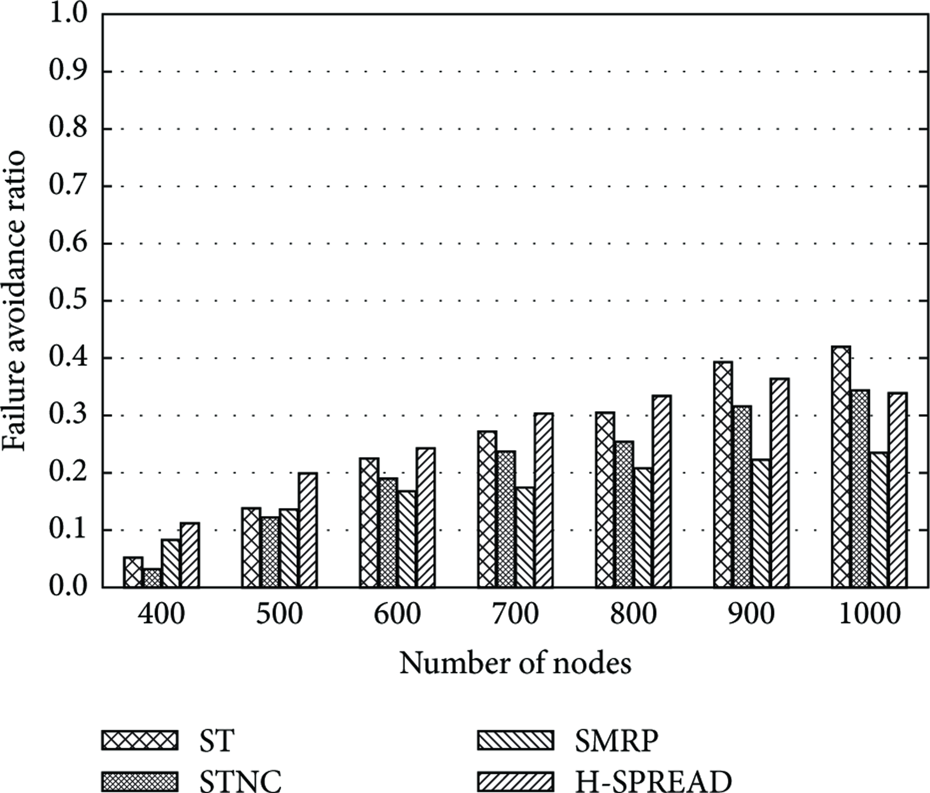
Figures7,8, and9 show the failure avoidance ratio when the failure area radius is 20 m, 60 m, and 100 m, respectively. In high density topology, shortly after the failures, ST scheme offers the largest collection ratio, followed in order by STNC scheme, H-SPREAD scheme, and SMRP scheme. As expected, making a Side Trip enhances resistance to spatial node failure. Then, in STNC scheme, no data could be recovered from encoded packets by the sink node if packets whose data are included in the encoded packet are lost. On the other hand, in ST scheme, either just an original packet or its corresponding redundant packet has to survive. This is why ST scheme is superior to STNC scheme in terms of the resistance to spatial node failure. H-SPREAD scheme and SMRP scheme are inferior to ST and STNC because they fail to spatially separate the primary and secondary paths sufficiently. Further, the reason why SMRP scheme has the lowest collection ratio is that some nodes failed to secure a secondary path as explained in Section2.2. On the other hand, in low density topology, FAR of H-SPREAD scheme is the highest. Note, however, that each scheme has lower FAR than that in high density topology. This is because that many nodes could not find a secondary path. Therefore, in order to enhance the tolerance, node density should be high to a certain extent.

Failure avoidance ratio with node failures (failure area radius is 20 m).
Failure avoidance ratio with node failures (failure area radius is 60 m).
Failure avoidance ratio with node failures (failure area radius is 100 m).
Next we evaluate how multipaths are disjointed from each other. To do so, we define distance as a Euclidean distance between nodes which exist on primary path and secondary path at one level lower than source node. Figure10 shows the average distance between multipaths when the number of nodes is 1,000. From this figure, we can see that ST(NC) scheme has longer distance than SMRP scheme and H-SPREAD scheme. This is because, in H-SPREAD scheme and SMRP scheme, when nodes discover multipaths, they choose second shortest path as a secondary path or use information of only one-hop neighbor nodes. This shortens the distance. Further, in SMRP scheme, source nodes at level 2 have a distance of zero since SMRP scheme uses tree topologies rooted at second-level nodes. On the other hand, ST(NC) scheme tries to detour a secondary path at the same level as a source node, and it utilizes tree topologies rooted at first-level nodes. From this figure, it can be confirmed that ST(NC) scheme is effective in separating multipaths spatially.
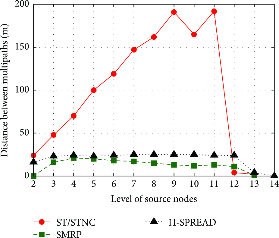
Average distance between multipaths.
The average delays until all of data are collected are 275.54 s, 226.55 s, 213.12 s, 256.62 s, and 83.34 s in ST scheme, STNC scheme, SMRP scheme, H-SPREAD scheme, and SP scheme, respectively. The delay of SP scheme is shorter than that of the others. This is because SP scheme uses only one path. In ST scheme and STNC scheme, ST phase prolongs the delay. However, STNC scheme has smaller delay than H-SPREAD scheme. This is because NC reduces the number of redundant packets. SMRP scheme has the shortest delay except ST scheme. This is because it generates fewer redundant packets than the others.
From the above results, we could confirm that STNC scheme achieves the highest possible resistance to spatial node failure without shortening the system lifetime significantly in high density topology. ST scheme is the best in terms of resistance to spatial node failure but with a slight penalty in system lifetime and delay. If system lifetime and delay do not matter, ST scheme is the best choice.
5. Conclusions
One of the important issues is to create data-gathering WSNs that offer enhanced resistance to spatial node failures. Existing multipath schemes, that is, H-SPREAD scheme and SMRP scheme, however, do not have insufficient spatial node failure tolerance because primary and secondary paths are not spatially separated enough. In this paper, we have proposed the Side Trip (ST) scheme and Side Trip with Network Coding (STNC) scheme; both offer improved resistance to spatial node failure. Our simulation results show that, in high density topology, ST scheme achieves the highest collection ratio in the case of spatial node failure; STNC offers the next highest ratio without affecting the system lifetime significantly. Considering that the WSNs tend to consist of a lot of nodes which are deployed in high density, ST scheme and STNC scheme are efficient to achieve tolerance to spatial node failure without shortening the system lifetime significantly.