
Abstract
Internet of Things (IoT) is expected to become a driver in an emerging era of interconnected world through the advanced connectivity of smart devices, systems, and services. IoT goes beyond a broad range of Machine-to-Machine (M2M) communication technologies and covers a wide variety of networking protocols. There exist solutions like MQTT or SIP collecting data from sensors, CoAP for constrained devices and networks, or XMPP for interconnecting devices and people. Also there is a plethora of standards and frameworks (OSGi, AllJoyn) bringing closer the paradigm of IoT vision. However, the main constraint of most existing platforms is their limited mutual interoperability. To this end, we provide a comprehensive description of protocols suitable to support the IoT vision. Further, we advocate an alternative approach to already known principles and employ the SIP protocol as a container for M2M data. We provide description of data structures and practical implementation principles of the proposed structures (JSON and Protocol Buffers are discussed in detail) transmitted by SIP as a promising enabler for efficient M2M communication in the IoT world. Our reported findings are based on extensive hands-on experience collected after the development of advanced M2M smart home gateway in cooperation with the operator Telekom Austria Group.
1. Introduction
Presently, the world around us is humming with data from smart meters, sensors, or actuators. Everyday devices like energy meters, water meters, or environment sensors are no longer isolated entities performing their tasks offline. In contrast, the goal of smart devices is to make our personal and business lives easier and more efficient—today, we can see a wide variety of smart devices (e.g., smart meters, sensors, and actuators) coming on the market in waves and targeting to bring intelligent behavior into today's households [1]. All kinds of such devices are interconnected within one communication paradigm named Internet of Things (IoT) where the tremendous volumes of measured data need to be transmitted.
Following the fact that over the last decade the IoT has attracted an enormous interest from numerous industry domains [1], the number of Machine-to-Machine (M2M) connections will grow to over 3 billion in 2019. Hence, there is a crucial need to develop appropriate communication protocols for M2M (together with appropriate data structure/format) to manage data from different sources—storing, organizing, and analyzing data to enrich the new businesses with novel revenue streams and valuable services (frameworks) [1,2].
Envisioning the future of M2M communication, the telecommunication operators will play a key role in providing and supporting the communication infrastructure between end devices. Today, the 4G and beyond cellular networks (Long Term Evolution, LTE) increasingly introduce support for M2M communication capabilities [3]. However, IoT brings along new challenges which cannot be solved by a single technology. Therefore, we are likely to encounter a new paradigm called 5G vision or 5G ecosystem providing the bridge between a massive number of smart devices deployed, for example, within a connected home and remote application running in cloud [4,5]; see Figure1.

Communication chain representing today's IoT structure: data from smart meters and sensors (Stage I) is transmitted via communication protocols (e.g., WM-BUS and ZigBee) supported by meters/sensors to aggregation unit called MTCG (Stage II). After performing aggregation logic, data is transmitted via the cellular networks (Stage III) towards the end (remote) application/service provider (Stage IV).
It becomes obvious that, to manage devices and services in IoT, more than one communication protocol has to be deployed [6,7]. On the other hand, it is not always necessary to develop entirely new platforms to satisfy the demands of IoT services, but also already existing protocols should be taken advantage of as possible candidates for certain IoT use cases. For example, if we take a closer look at the architecture of LTE networks [5] we can see that the IP Multimedia Subsystem (IMS) is a mandatory part of LTE architecture providing the possibility of using Session Initiation Protocol (SIP) for transmitting M2M data [8–10]. Taking into account that SIP represents a lightweight communication protocol independently of the carried data, the question is whether it is feasible to use the SIP protocol as an alternative to other protocols like Message Queuing Telemetry Transport (MQTT) [11,12], Constrained Application Protocol (CoAP) [13], Advanced Message Queuing Protocol (AMQP) [14], Data Distribution Service (DDS) [15], or Extensible Messaging and Presence Protocol (XMPP) [16] for communicating the M2M data [17].
Inspired by that, in this paper, we deliver a comprehensive discussion on remote data management architecture in IoT including the summary of proof-of-concept implementation of SIP-based data sharing between smart home gateway and remote service entities where the JavaScript Object Notation (JSON) as data format transmitted within the SIP messages carrying M2M data from a wide variety of real meters/sensors is utilized (described implementation was completed as a part of SyMPHOnY project which stands for the joint project realized by Brno University of Technology (BUT) and Telekom Austria Group (TAG) [18]) [19,20]. In this research, we proposed and implemented our own JSON structure for transmitting M2M data which meets the requirements imposed by industry [21]. Therefore, we believe that our approach is adequate and sufficiently scalable to support M2M applications across future deployment of LTE and future cellular networks.
The rest of the paper is organized as follows. Section2 is devoted to describing possible application protocols for M2M communication in cellular networks. Following the described application protocols, the bidirectional communication as a key function is described in Section3. Further, in Section4, a discussion on suitability of JSON and Protocol Buffers formats for IoT (M2M) is offered. Our implementation of created structures as part of the real use case for Telekom Austria Group (TAG) is provided in Section5. Finally, the lessons learned during the implementation of the JSON and Protocol Buffers within the development of MTCG (smart home gateway) for M2M data are summarized in concluding Section6.
2. IoT Protocols
Following the concept of IoT, devices must be able to communicate with each other—referred to as M2M communication [22]. Further, data from devices should be stored at the central point (MTCG) and as a next step sent to the remote server. Many IoT standards and recommendations were proposed to implement the described idea of IoT. Therefore, different development groups and standardization initiatives have been formed to pave the road towards the demanded communication protocols (in case of IoT we mean application protocols); the most important representatives include World Wide Web Consortium (W3C) [23], Internet Engineering Task Force (IETF) [24], Institute of Electrical and Electronics Engineers (IEEE) [25], and the European Telecommunications Standards Institute (ETSI) [26]. Table1 provides a summary of the most prominent protocols defined by these groups.
Standardization activities in support of IoT.
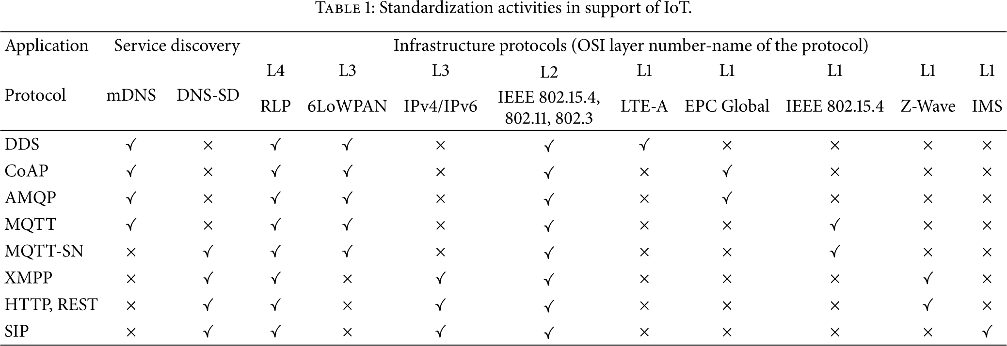
In this section, we provide an overview of the popular protocols and their core functionality (with respect to their ability to be used as M2M containers).
2.1. Message Queue Telemetry Transport (MQTT)
MQTT is the messaging protocol introduced in 1999 and standardized in 2013 at OASIS [27]. The protocol itself was aimed at enabling connection between embedded devices and networks with various applications [11,12]. MQTT works with publish/subscribe pattern to provide flexibility and simplicity of implementation as can be seen in Figure2. Focusing on the target group of devices, the MQTT (running above TCP protocol) is appropriate for embedded (resource/power-constrained) devices using unreliable or low-bandwidth links. Nowadays, two main specifications exist for MQTT: (i) MQTT v.3.1 [11] and (ii) MQTT-SN (also known as MQTT-S) [12].

The architecture of MQTT protocol.
MQTT consists of three key components: (i) subscriber, (ii) publisher, and (iii) broker. An interested device can register as a subscriber for the specific content in order to be informed by the central point (broker) every time when a publisher disseminates information of interest [11]. In this architecture, the publisher stands for the meter/sensor sending data to MQTT broker. Secure communication between all parts is achieved by verifying the authorization of publishers and subscribers on the side of broker [12].
The message format of MQTT protocol is depicted in Figure3. The first two bytes are part of fixed header. Further, the field Message Type contains a variety of messages, for example, Connect (1), Connack (2), Publish (3), and Subscribe (8).

MQTT message format [11].
Next, the DUP (duplicate) flag informs that the message is duplicated and receiver may have acquired this message already before. The QoS field stands for identification of three QoS levels for delivery of Publish messages. The following field is called Retain and informs the server to retain the last Publish message and submit this message to the new subscribers (this message will be sent as the first message). The last field (Remaining field) indicates the remaining length of the message (i.e., optional parts).
From the M2M communication point of view, the main disadvantage of MQTT is the fact that end devices which use MQTT protocol may go to sleep state for a limited time period only (e.g., a lot of sensors or smart meters send the data once per few hours and therefore MQTT is not a suitable communication protocol for these power-constrained devices).
2.2. Constrained Application Protocol (CoAP)
CoAP was created by the IETF Constrained RESTful Environments (CoRE) working group as the application layer protocol for IoT applications [13,28]. CoAP introduces web transfer protocol based REpresentational State Transfer (REST) on top of HTTP. In contrast to REST, CoAP is utilizing lightweight UDP as transport protocol (TCP is not supported) by default. This makes CoAP more suitable for the IoT domain because it is possible to build sufficiently basic error checking and verification for UDP to make sure that messages arrived without the significant communication overhead in case of TCP. However, CoAP was designed together with REST functionality; therefore conversion between these two protocols has to be implemented in communication chain; see Figure4.

CoAP functionality [13].
CoAP can be divided into two sublayers [28]:
Messaging Sublayer. It detects duplications and based on that provides reliable communication even over the UDP transport protocol using the exponential backoff (multiplicative decrease of the rate of data transmission, in order to gradually establish an acceptable data rate); this is a necessary technique since UDP does not include error recovery mechanism. Request/Response Sublayer. It handles REST communication between individual nodes.
CoAP utilizes four message types: confirmable, nonconfirmable, reset, and acknowledgment. Reliability of CoAP is achieved by using confirmable and nonconfirmable messages. Similarly to HTTP, CoAP utilizes methods such as GET, PUT, POST, and DELETE to perform Create, Retrieve, Update, and Delete operations; for example, the GET method can be used by a server to inquire the client's temperature using the response mode. The client sends back the temperature if it is available; if not, it replies with a status code to indicate that the requested data is not found.
Message format of CoAP is depicted in Figure5. The first and fixed part of each message consists of four bytes of a header. Then a token value may appear whose length ranges from zero to eight bytes. A typical length of CoAP message can vary between 10 and 20 bytes [29]: this means that CoAP may be unsuitable for some domains of IoT.

CoAP message format [13].
Remark. There are studies describing the possible use cases where CoAP messages are transmitted via Short Message Service (SMS) [28]; this makes another logical bridge towards the idea to use SIP communication protocol as a data container for IoT domain.
2.3. Extensible Messaging and Presence Protocol (XMPP)
XMPP represents an IETF instant messaging (IM) standard for chatting, voice and video calling, and telepresence [16]. XMPP allows IM applications to run authentication, access control, privacy measurements, and especially Device-to-Device (D2D) and end-to-end (E2E) encryption. The overall functionality of XMPP protocol is depicted in Figure6 where gateway can overcome issues with sending messages between foreign networks; XMPP connects clients and servers using the XML called stanza [30].
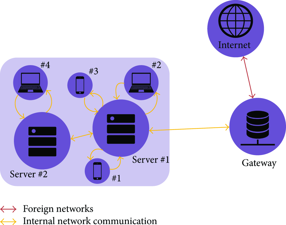
Communications in XMPP [16].
Integrated features make XMPP a preferred protocol by most IM applications and therefore relevant for specific part of IoT ecosystem. XMPP also implements a building block for secure communication and allows new applications on top of core protocols [16]. As was mentioned, XMPP uses the so-called stanzas which divide the code into three components: (i) message, (ii) presence, and (iii) info/query; see Figure7.

Structure of XMPP stanza [30].
Messages in stanza identify the source and destination address, types, and IDs of XMPP entities that provide PUSH method for retrieving data. The presence stanza notifies end users of the status updates. Finally, the iq stanza does the pairing between message senders and receivers. The possible disadvantage of XMPP is text-based communication using XML. This leads to higher network load (overhead). Therefore, there is a possible solution to this problem: XML streams using EXI [31,32].
XMPP is very often compared with the SIP protocol where SIP is inherently a peer-to-peer protocol whereas XMPP is inherently client-server. Tasks that are easy in client-server systems, for example, to share state, to save data on server, or to post offline messages on server, are well accomplished with XMPP protocol. On the other hand, one of the primary goals of SIP (described later in this section) is to keep the intelligence at the end point. Ideally, a SIP proxy server does not even maintain the session state for the SIP dialog [16].
2.4. Advanced Message Queuing Protocol (AMQP)
AMQP represents the open standard application layer protocol focusing on the message-oriented environments in IoT [14]. Further, AMQP enables guaranteed communication—it requires a reliable TCP session to exchange messages.
Communication via the AMQP is realized by two key components (see Figure8) [33]:
Exchanges. They are used for routing messages to appropriate queues. Routing (between exchanges and queues) is based on predefined rules/requirements. Message Queues. They are stored in message queues before sending to end destination (receiver).
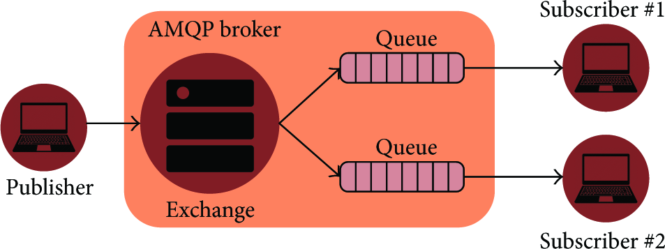
AMQP publish/subscribe mechanism [14].
AMQP defines messaging layer on top of the transport layer (TCP is used as the transport protocol) where all messaging capabilities are handled. Following that, two types of messages are defined in AMQP: (i) bare messages (at the sender's side) and (ii) annotated messages (at the receiver side); see Figure9.

AMQP message format. The header enables a delivery of parameters including durability, priority, time to live (TTL), first acquirer, and delivery count [14].
As discussed, AMQP requires extensions implemented on transport layer for the aforementioned messaging layer. In case of transport layer, the communication is frame-oriented. The structure of AMQP frame is depicted in Figure10.

The first four bytes indicate the frame size. DOFF (Data Offset) represents the position of the body inside the frame. The Type field indicates the format and purpose of the frame. For example, 0x00 is used to show that the frame is an AMQP frame or type code 0x01 represents a SASL frame.
In the IoT context, AMQP is the most appropriate for the control plane or server-based analysis functions. Therefore, it is not a suitable candidate for transmission of M2M data (E2E communication).
2.5. Data Distribution Service (DDS)
DDS was designed as a publish-subscribe protocol for real-time M2M communications by Object Management Group (OMG) [15,34]. In comparison with the aforementioned protocols like MQTT or AMQP, DSS uses multicasting to provide better reliability and Quality of Service (QoS). DSS supports 23 QoS policies by which a wide variety of communication use cases can be covered, for example, security, priority, and reliability. The DDS logic is therefore able to meet the real-time requirements given by specific types of IoT/M2M.
Architecture of DDS defines two layers: (i) Data-Centric Publish-Subscribe (DCPS) and (ii) Data-Local Reconstruction Layer (DLRL). DCPS layer is responsible for delivering information to the end destinations (subscribers). DLRL represents, on the other hand, optional layer which serves as the bridge/interface to the DCPS functionalities (sharing of distributed data among distributed objects) [35]. In DCPS layer, five entities are managing the data flow (see Figure11):
Publisher. It sends required data sets. DataWriter. It is used by the application to interact with the publisher with respect to values and changes regarding data type. The thin cooperation between Publisher and DataWriter is used by application for publishing data in provided context. Subscriber. It receives data from Publisher and transfers them to the application. DataReader. It is controlled by Subscriber to read the received data. Topic. It is defined by data type and name and connects DataWriters with DataReaders.

Conceptual architecture of DSS [15].
2.6. Comparison of Already Described Protocols
Based on the abovementioned facts, it can be seen that MQTT, XMPP, or CoAP can be used as protocols for M2M data, but still there are limitations (e.g., message length and sensors inactivity) mainly associated with end-to-end connectivity. In literature, several comparisons between these protocols can be found. For example, in [36] the authors compare end-to-end transmission delay and bandwidth utilization of MQTT and CoAP; MQTT delivers required data with lower delay in comparison to CoAP in case of low packet loss. Otherwise, in case of high packet loss, CoAP gave better results. In another research [37], the attention was focused on smartphones application environment. Results show that CoAP offers lower bandwidth usage and lower round trip time (RTT) than MQTT.
Offering a new point of view in this space, in our project [38], we propose a novel way to transmit M2M data through the network—with respect to length of transmitted data, transmission scheduling, and E2E nature of M2M communication. As discussed in Section1, the SIP protocol is a common part of today's cellular networks and even though it was invented for different applications like IP telephony, multimedia streaming, and instant messaging, it is an excellent candidate to become a primary communication bus for the constituent components of IoT ecosystem (as a part of the emerging 5G vision).
2.7. Session Initiation Protocol (SIP)
SIP represents the text-based request-response protocol (in a way similar to HTTP) where the key attributes are included in the header and additional data is stored in the message body (e.g., session description or capabilities). Nowadays, SIP is well established in both local and global telecommunication infrastructures and there is a plethora of end user devices and applications supporting this protocol [38]. Therefore, there is no need to invest additional resources to implement this protocol within IoT domain [8].
Although the SIP works in parallel with other communication technologies and protocols (e.g., TCP, UDP, or Stream Control Transmission Protocol (SCTP) can be used as transport protocols for SIP) there are two key components used by SIP [8] (see Figure12):

Communication in SIP [8].
User Agents. End points of the communication chain are often named as SIP clients. There are two subcomponents of a user agent: (i) client and (ii) server. When there is a request (e.g., to initiate a session) generated by User Agent Client (UAC), responding user agent (at the opposite side) is User Agent Server (UAS). It is important to understand that as the user agent will send message and then respond to another user agent, it will alternate between both roles during a session.
SIP Servers. They are used to resolve usernames to IP addresses. A user agent (see previous paragraph) registers with the SIP server (providing username, IP address, and location information). This procedure verifies whether the user agent (SIP client) is online, so that other user agents can see whether they are available and can start a session. If the user agent does not belong to a certain SIP domain (different SIP server), it will send request to other servers. SIP server can act in any of the following roles: (i) registrar server, (ii) proxy server, and (iii) redirect server [8].
The format of SIP header is depicted in Figure13 and structure of SIP protocol comprises three layers:
Transport Layer. It defines how the SIP client (user agent) sends requests and receives responses and how SIP server receives requests and sends response over the network. It is important to mention that all SIP elements work within transport layer. Transaction Layer. It serves for sending requests (from SIP client to SIP server, using transport layer). Any task completed by SIP client comprises a series of transactions (stateless proxy servers do not contain transaction layer). Transaction User. Each of the SIP entities (SIP clients and SIP servers except the stateless proxy servers) acts as transaction user.

SIP message format [8].
The question of security communication is also covered by SIP since the Secure Sockets Layer (SSL)/Transport Layer Security (TLS) mechanisms are already prepared for secure communication between SIP clients. For the purposes of M2M (home automation) communication, SIP MESSAGE (for PUT and GET actions) and SIP SUBSCRIBE (for status-based events like alarm notification) can be used [8].
2.8. IoT Application Protocols Summary
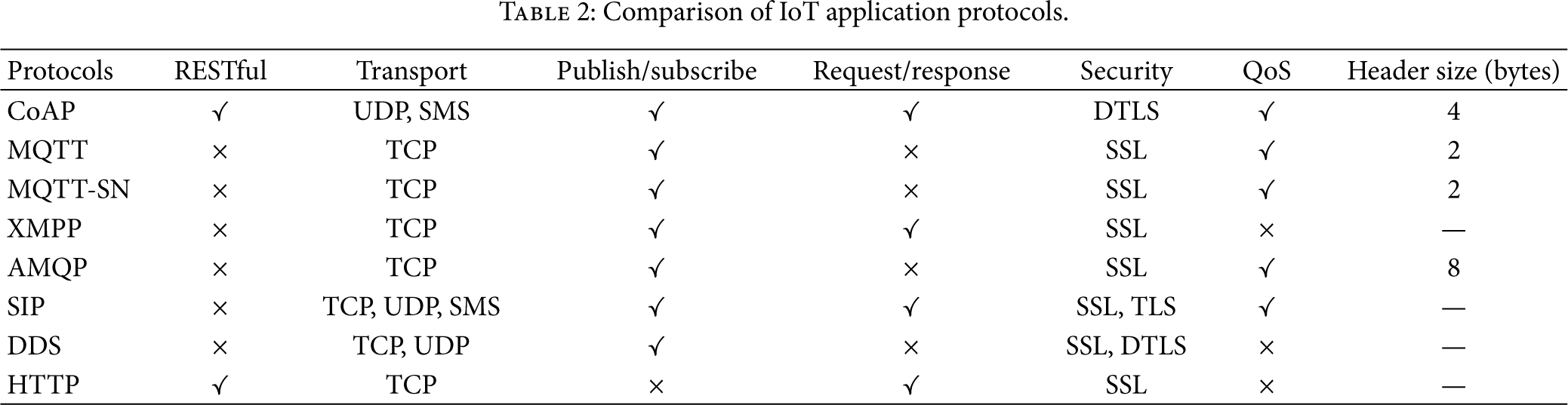
To conclude this section, three protocols are mentioned very often in the context of M2M communication: MQTT (Section2.1), CoAP (Section2.2), and SIP (Section2.7). In addition to MQTT and CoAP, the SIP has been recognized as an efficient data container for home automation/IoT communication [18,38]; see Table2 for comparison of IoT application protocols. Moreover, open-ended nature of SIP (where the SIP MESSAGE can contain any data structure with dynamic length) provides a solid basis to address issues specific to the home/industry automation domain. Together with the operators' maintained infrastructure, the SIP constitutes a secure and reliable communication protocol for remote IoT services.
Comparison of IoT application protocols.
3. Bidirectional Communication in IoT Application Protocols
In the previous section, we discussed the most frequently used protocols in IoT domain. Together with the described (overall) parameters of each protocol, there is one additional requirement which impacts the choice of an appropriate application protocol. Nowadays in IoT, the one-way communication is no longer the predominant type of data transmission between sensors and cloud apps. We often encounter an emerging need for remote controlling and adjustment of smart devices (meters, sensors, actuators, etc.). Therefore, the two-way (bidirectional) communication plays the key role in today's IoT architecture [1].
In this section, the protocols previously identified as the most attractive (i.e., CoAP, MQTT, and SIP) are described and compared mindful of the two-way communication feature.
3.1. CoAP
CoAP employs two-layer structure: (i) the bottom layer is called message layer and has been created to deal with the UDP transport protocol and asynchronous switching; (ii) the request/response layer manages communication method and also request/response message.
3.1.1. Message Layer
Message layer of CoAP protocol consists of 4 message types: (i) CON (confirmable), (ii) NON (nonconfirmable), (iii) ACK (acknowledgment), and (iv) RST (reset) [13,28]. The communication via message layer model can be divided into two groups:
Reliable Message Transport. The transmission is maintained until the same message ID (like 0x8b56; see Figure14(a)) in ACK message is received at the side of the client. If server fails to process the incoming message, it responds by replacing the ACK with the RST message. Unreliable Message Transport. It is transported with the NON type message. There is no need to send ACK, but the message has to contain message ID for the purpose of retransmission. If server fails to process message, it responds by RST; see Figure14(b).

3.1.2. Request/Response Layer
Using the request/response layer model, the communication can be handled as follows:
Piggy-Backed Approach. In this case, the client sends request (using the CON or NON message) and receives ACK message. If the transmission is successful, the ACK contains response message which is identified by token (0x21; see Figure15(a)). In case of failure, the ACK contains failure response code (see Figure15(b)). Separate Response. In the case when the server receives CON message and is not able to respond immediately, it sends an empty ACK message to the client. When the server is ready to respond to the request, the new CON message is sent to the client. At the client side, the confirmation message with ACK is sent back to server; see Figure16(a). Nonconfirmable Request/Response. Unlike the piggy-backed approach, the request is sent from a client to the server in NON type message which indicates that the server does not need to confirm the incoming message. After receiving the message, the server sends a NON type message with response (see Figure16(b)).

The successful and failed response results of GET method [13].
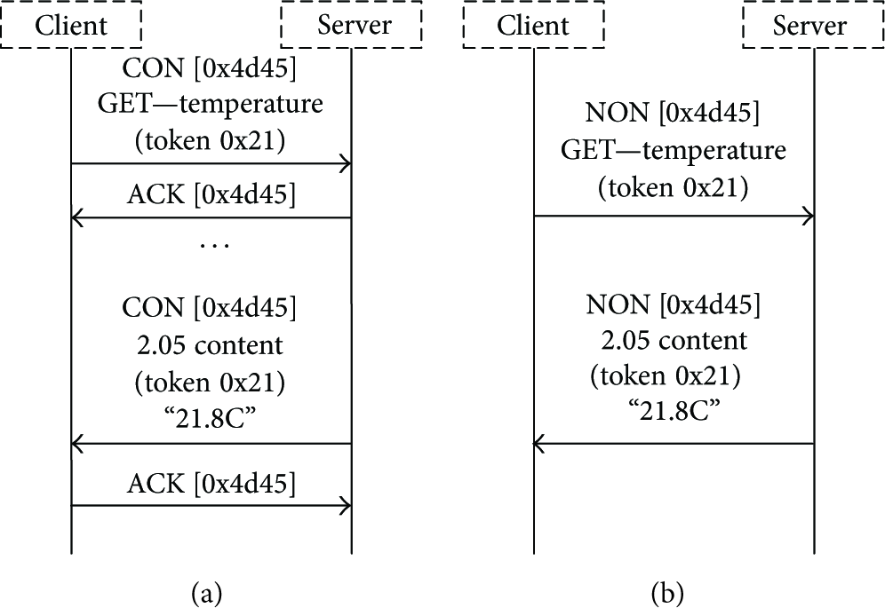
(a) Get request with a separate response; (b) nonconfirmable request and response [13].
3.2. MQTT
Even though the MQTT application protocol is mentioned very often as a leading candidate for IoT domain [39], it does not support the request/response communication; see Table2. This restriction limits the range of possible use cases where the MQTT can be used. The only available scenario of bidirectional communication with MQTT illustrates the publish/subscribe communication model. With one client in the role of publisher and one or more nodes as subscribers, the information can be sent from a single point to many other devices or listeners. Therefore, the deployment of this application protocol becomes straightforward; see Figure17.

Publish/subscribe process utilized by MQTT [11].
3.3. SIP
As discussed in Section2.7 and highlighted in Table2, the SIP stands for the request/response application protocol. Sending M2M data via the SIP requires different behavior comparing to the traditional voice communication via SIP (e.g., the media session (RTP) is not established). In general, using SIP for IoT/M2M, the overall communication procedure comprises three steps [8,9]:
Registration to the SIP Server. Each SIP client has to register to the SIP server to be able to receive or send the data; see Figure18. The registration process is completed by the 200 OK message sent from the server to the SIP client. Depending on the SIP (IMS) network configuration, the registration process has to be reestablished in a loop. M2M Data Request/Response. After the registration process is completed, the M2M data can be transmitted using the SIP. Since the SIP was designed for request/response communication, this can be done via the SIP message which carries the request or response; see Figure19. Request is sent to the SIP server which will answer back to SIP client with the 407 Proxy Authentication Request. Next, the SIP client sends the message (request) with digest to the SIP server and this message is resent to the end SIP client. In case of response, the destination node will send the message 200 OK as a confirmation. Using the modularity of SIP, inside the 200 OK message, the response to the source SIP client is included (the format inside the request/response SIP messages can differ; e.g., JSON of Google Buffers [40] can be used; see Section4). Termination of SIP Connection. The procedure of deregistration of SIP clients from the SIP server follows the rules mentioned in the registration process. SIP client sends the SIP message Unregister to the SIP server which answers with the 401 unauthorized message. After that, SIP client sends the SIP message Unregistered with digest. As a response from server, the 200 OK is sent back and the connection is closed [8].

SIP registration procedure [8].

Request/response communication using the SIP protocol [8].
Remark on Reliable SIP Communication. SIP represents the transactional protocol which means that interactions between components (UAC and UAS) take place in series of independent message exchanges. Specifically, a SIP transaction consists of one request and many responses to that specific request. Transactions feature client (called client transaction) and server (known as server transaction) parts. The client and server transactions are logical functions embedded in all elements (they exist in user agents and stateful proxy servers); see Figures19 and20.

Transaction relationships in SIP [8].
Following the fact that SIP uses mainly the UDP transport protocol, the question of reliable communication is raised here. Especially for request/response it is crucial to know if the message was delivered or not. For that, SIP implements the logic where, with every transaction, the CSEQ number (transaction ID) is incremented for each new request within the dialog as a traditional sequence number [8].
4. Data Formats for M2M
While considering SIP as a perspective IoT communication protocol, we aimed at developing an appropriate data structure inside the SIP message. Nowadays, JSON format [41] acts as one of the most acknowledged drivers in case of IoT/M2M data structure. On the other hand, there are new emerging projects trying to rethink the aspect of M2M data sharing. One of them is Protocol Buffers [40] which stands for Google's language-neutral, platform-neutral, extensible mechanism for serializing structured data.
However, after evaluating the state-of-the-art data structure formats, we chose the JSON format as our main data format which is easy to read and write and in comparison with the XML, the structure is more suited for generating and further handling (parsing and converting). Another advantage of using JSON is shorter message length since JSON can describe an individual object very efficiently [42]. To provide the comprehensive evaluation, we also develop a practical example of IoT data structure utilizing the Protocol Buffers which enables a direct comparison of two different approaches.
4.1. JSON Structure
JSON is based on a subset of JavaScript using the text format that is completely independent of programming language, but at the same time it also uses the rules similar to C family (including C, C++, C#, Perl, or Python). These properties caused JSON to quickly become a popular data interchange format.
It is very important to mention at the beginning of this section that JSON as a generic data structure can be implemented in various types of communication protocols, for example, the SIP, CoAP, and MQTT communication protocols, and is suitable to carry different types of payloads. Following this fact, the proposed JSON structure (data format) in this paper can be also implemented as part of other protocols (for different use cases where CoAP or MQTT may represent better choices comparing to the SIP).
Currently, the JSON is based on two data structures [43]:
Collection of Pairs (Name-Value). This is in many programing languages implemented as object, record, hash table, or associative array. Ordered List of Values. It is often realized as an array, vector, list, or sequence.
The above structures are universal and almost all modern programing languages support them. Therefore, JSON data format is interchangeable with respect to the programming languages based on the following structures [43]:
Object. It is an unordered set of pairs (name-value). An example of object in JSON is depicted in Figure21.
Array. It is an ordered collection of values. An example of array in JSON is depicted in Figure22.
Value. Examples of different types of values are depicted in Figure23.
String. It is very similar to C or Java string notation. An example of string in JSON is depicted in Figure24.
Number. It is very similar to C or Java string notation. An example of number in JSON is depicted in Figure25.

Source code notation for JSON:object: each name is followed by : (colon) and pairs are separated by , (comma) [42].

Source code notation for JSON:array: it begins with the [(left bracket) and ends with] (right bracket). Values are separated by , (comma) [42].
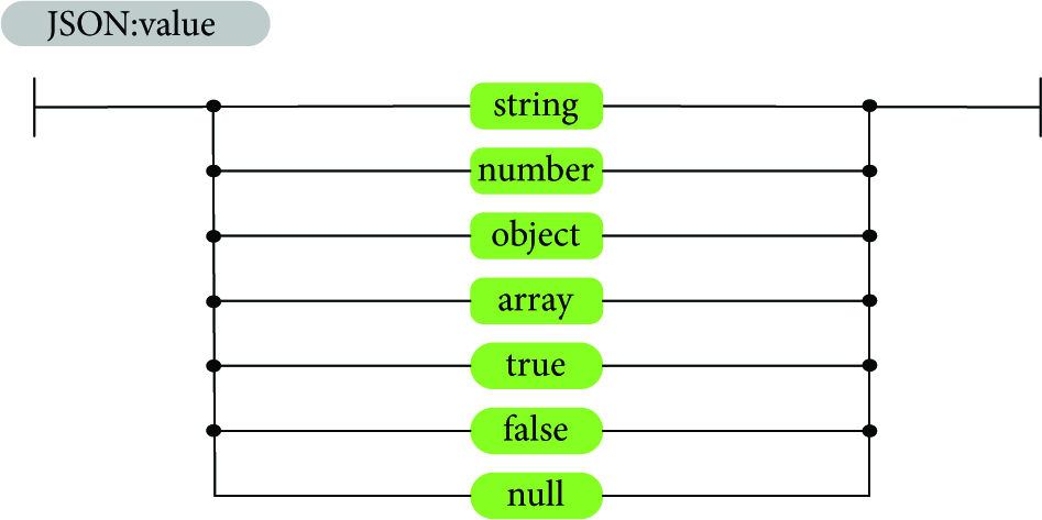
Source code notation for JSON:value: it can be represented as a string in “ ” (double quotes), number, true, false, null, or an object or an array [42].

Source code notation for JSON:string: sequence of Unicode characters in “ ” (double quotes) using ∖ (backslash) escapes. A character is represented as a single character string [42].

Source code notation for JSON:number: similar to C or Java, it does not contain the octal and hexadecimal formats [42].
The described options represent the most frequently used JSON structures; a detailed overview of available structures can be found in [43].
Due to the wide variety of possible JSON messages, a lot of examples for different use cases can be found in literature [44–46].
4.2. Protocol Buffers Structure
There are many possible views on the problem (data structure for M2M content) presented by this paper and, consequently, a number of feasible solutions. As described above, JSON structure is one of the most promising solutions and therefore, we have utilized this approach in our practical implementation. However, another emerging candidate is Protocol Buffers which is a recently introduced tool for serialization of structured data provided by Google.
Currently, Protocol Buffers exist in two language versions, called proto2 (latest stable release) and proto3 (alpha version). In this subsection we discuss the proto2 capabilities and structure as stable implementation recommended by Google.
Protocol Buffers are able to work with a variety of programming languages such as Java, C++, C#, and Python. The basic idea of Protocol Buffers is similar to that in JSON. In the first step, structure of serialized data is defined. This is done in .proto file by defining Protocol Buffer messages type. Each of these messages is a small logical record of information, containing series of fields with name-value pairs. There are a number of different types used for the value definition. Examples of these types are depicted in Figure26. Aside from those types, there is one special type of field, called Enum. Its purpose is to predefine values in a list, so no other data can be put inside.

Source code notation for Protocol Buffers: value type.
Message fields are assigned with unique numbered tags. Those tags are used to identify fields in the message binary format and should not be changed once message type is in use. Tag numbers can be chosen from the range Required. It is obligatory to fill this field with data. Optional. Any message field with this rule may or may not be filled with data. Repeated. Fields with this rule can be repeated several times including zero.
4.3. Review of Introduced Thoughts
Before proceeding with the description of realized implementation in the following section, a short summary on ideas discussed in previous sections is appropriate. We have introduced the well-known application protocols with respect to the IoT domain. Instead of using traditional protocols, we have based our implementation on SIP protocol which can act as the container for M2M data. On top of that, we introduced two new data structures for M2M data based on (i) JSON and (ii) Protocol Buffers schemes.
5. Implementation of Proposed Data Structures in Live Smart Home Project
In this section, we focus our attention on practical implementation of two data structures: JSON (Section5.2) and Protocol Buffers (Section5.4). Our goal is to identify a suitable data structure for transportation of M2M data from a large number of meters/sensors to a concentrator node (MTCG); see Figure29. Since a variety of meters can proliferate in the market, we have been investigating an easily expandable and universal data structure.
First, the overview of the entire communication structure of our SyMPHOnY (Smart Multipurpose Home Gateway) project is given in Section5.1. Next, the generic JSON scheme is described in more detail in Section5.2. Further, the attention is focused on the JSON and Protocol Buffers data structures; see Sections5.3 and5.4, respectively.
5.1. Overall System Architecture
As discussed earlier in Section2, we chose SIP as a communication protocol for data transmission. In our architecture (see Figure29), the MTCG node assumes role of SIP client where data is (i) received (e.g., via wireless M-BUS interface) from a wide variety of smart devices and (ii) sent via the IMS/SIP network (using the SIP server as an intermediate node) towards the remote SIP client [47].
5.1.1. SW Implementation on the MTCG
The created application framework is written in Java programming language and follows requirements given by the Open Services Gateway Initiative (OSGi) [48]. Following that fact, our solution is divided into several packages called bundles. Each of the created bundles manages a certain subtask (e.g., receiving data from specific communication protocol and acting as a SIP client at the MTCG side) and ultimately the entire logic is managed by the Core Bundle; see Figures27 and28.

General structure of created framework in the SyMPHOnY project [18].

Architecture of SIP client bundle in SyMPHOnY [18].

SyMPHOnY is able to aggregate information from arbitrary smart devices and automate actions based on user-defined or network-defined policies using telecommunication operators' technologies. In our project, the SIP communication is implemented as key remote data exchange technology.
Our developed framework [18] is able to run on any device based on Acorn RISC Machine (ARM) architecture. Nowadays, there are pilot projects trying to run Java-based applications also on MIPS (Microprocessor without Interlocked Pipeline Stages) platform [49]. In addition, Oracle company announced plans for developing Java libraries for MIPS architecture. However, these projects are in early development stage and therefore we decided to use for our project IP gateway running the ARM SoC (System on Chip) [50]; as operating system, the OpenWRT 14.07 Barrier Breaker was used [51].
Since the SIP bundle is the key part of communication chain between MTCG and remote “cloud-based” app, we provide a deeper analysis of SIP implementation in Section5.1.1. Our solution is based on JAIN-SIP API [52] which explicitly supports RFC 3261 [8] functionality and the following SIP extensions: the INFO method (RFC 2976) [53], Reliability of Provisional Responses (RFC 3262) [54], Event Notification Framework (RFC 3265) [55], the UPDATE method (RFC 3311) [56], the Reason Header (RFC 3326) [57], the Message method (RFC 3428) [58] defined for instant messaging and the REFER method (RFC 3515) [59], Distributing Authoritative Name Servers via Shared Unicast Addresses (RFC 3581) [60], and the PUBLISH method (RFC 3903) [61]. Therefore, our implementation of SIP on our gateway (MTCG) does not need any additional packages/extensions.
5.1.2. SW Implementation on Remote SIP Client
Following the information in Section5.1.1, there are no special requirements for the remote SIP client since our solution follows standardized implementation of SIP protocol [8]. We tested X-Lite [62], ZoiPer [63], and Asterisk (client part of Asterisk running in the terminal) [64] and as a result all of them were able to successfully process data sent from MTCG. To make the overall process of data handling more effective, we created our own SIP client (source codes are available on GitHub [18]). This tool combines SIP client and logic for parsing received JSON-structured data. Furthermore, if there is a need for conversion of received data into another data format, we implemented conversion logic for LPEX (proprietary data structure used by electricity companies) and CSV [65] data structures (this highly depends on the requirements at the remote side (specific app/industry use case)).
5.1.3. Bidirectional (E2E) Communication
Considering the aforementioned facts, we covered also the question of E2E communication between smart devices and remote cloud-based applications. Today, the need for bidirectional communication grows. Even though the majority of transmitted M2M data is represented by one-way communication (from sensors to the cloud), in the future, two-way communication will play the key role [1]. To react accordingly, we implemented special bundles (see Figure27):
JSON Bundle. In it translation of data is received from meters/sensors to required JSON structure (supported by remote cloud app) which is subsequently included in SIP message. Cloud-API Bundle. It manages the commands (for smart devices) received from applications in the cloud at the side of aggregation node (MTCG).
Requirements related to bidirectional communications bring new challenges across the IoT communication chain; see Figure1. Concerning our proposed architecture in our SyMPHOnY project [18] we have the following:
At the side of cloud-based app, the request messages for smart meter/sensor (or even for group of smart devices) have to be included (in JSON format agreed on by both communication sides) into the body of SIP message (Stage II ↔ Stage III ↔ Stage IV). After the SIP message is received by SIP bundle (running under control of Core Bundle on MTCG), information about targeted sensor(s) is extracted from the SIP message body. Next, the appropriate data unit (which depends on the used communication technology at the sensor side) is generated (Stage II)—in parallel, the Core Bundle is checking if the requested sensor supports bidirectional communication. If not, the response to the cloud-based app is sent. During the final part (Stage I ↔ Stage II), the request generated by MTCG is sent to the target sensor where the relevant action will be performed. As an acknowledgment, the ACK message is sent back to the cloud-based app via the MTCG (Stage I → Stage II → Stage III → Stage IV).
The above communication chain does not touch upon the question of security which is even more important in case of two-way communication. In case of secure communication between MTCG and remote cloud-based app, one of the supported security mechanisms (SSL and TLS) can be used. The need for secure communication between MTCG and smart devices (Stage I ↔ Stage II) is closely connected with concrete device/technology and its support of encryption. Today, the most widespread encryption mechanism implemented by industry manufactures is Advanced Encryption Standard (AES 128) [66–69].
5.2. Proposed JSON Structure
Before we proceed with the description of the constructed JSON scheme, we need to clarify the question of why it is so important to implement into the structure the so-called system codes. The system code represents a unique identifier for the key objects in the data structure. Nowadays, the leading system code for M2M communication (especially in smart metering domain) is the Object Identification System (OBIS) code—in our project we use the OBIS as a main system code; as an example of another system code, the KNX system code can be mentioned [70].
The OBIS code identifies the corresponding device value and represents a text string composed according to the OBIS standard [71]. The main reason for using OBIS is that leading industry companies, dealing with metering, already implemented support for OBIS standard.
One of the benefits of using OBIS is evident during machine processing of collected data. A parser with knowledge of JSON (or Protocol Buffers) structure as well as utilizing principles of creating OBIS codes can easily process received data without knowledge of exact internal JSON/Protocol Buffers structure. Obtained data may therefore be processed by any system with OBIS code conversion mechanism knowledge. This makes communication between devices by two different vendors much easier.
The OBIS code consists of 6 groups marked by letters A to F. All of these may or may not be present in the identifier (e.g., groups A and B are often omitted). In order to decide to which group the subidentifier belongs, the groups are separated by unique separators A-B:C.D. The A group defines the medium (0 = abstract objects, 1 = electricity, 6 = heat, 7 = gas, 8 = water, etc.). The B group defines the channel. Each device, with multiple channels generating measurement results, can separate the results into the channels. The C group defines the physical value (current, voltage, energy, level, temperature, etc.). The D group defines the quantity computation output of specific algorithm. The E group specifies the measurement type defined by groups A to D into individual measurements. The F group separates the results partly defined by groups A to E.
Examples of OBIS codes for home automation [71].

5.3. JSON Structure: Real Data Sets
Now, let us further describe the created JSON structure. Following the developed JSON scheme available on GitHub [18], we provide an example of real data set regarding the electricity consumption measurement implemented within the pilot project with Telekom Austria Group. As can be seen, each of the measured values is clearly identifiable which is the key requirement for further actions with received data, for example, parsing or converting JSON into the different data format/structure.
When creating the message following the requirements given by JSON scheme, it is crucial to conform to that structure because any deviation can cause inadequate reading of desired values. The proposed structure uses all of our predefined properties to its best. There are three properties of object system: system is related to (i) gateway (type of gateway), (ii) location, and (iii) property data.
Data is an array property, consisting of two objects, related to information about current time at gateway and status message. The object device is described by five properties: type (“smart meter”), objectCodeVersion (this device uses ObisV2.9), id (this device uses two different identifications), timestamp, and data. The objects in the array data (within the “device”) have properties: name, value, units, info (additional information about measured value), and objectCode (because device uses OBIS as system code); see Algorithm1.
{ } { { } { { { { } }
Algorithm 1
5.4. Proposed Protocol Buffers Structure
Protocol Buffers represent the second used data structure. To distinguish from the provided JSON structure with real data set, the examples below show our proposed .proto structure from the scheme viewpoint. The provided structure is divided into 7 parts which follow the idea of JSON structure:
Message FullJSONPacket consists of optional field system and required field device. Those fields feature messages defined as shown in Algorithm2. Message System includes an optional field type with value type string and two optional fields composed of messages as shown in Algorithm3. Message Device consists of required field of value type string called type, optional field of value type string called obejctCodeVersion, repeated field id, required field of value type string called timestamp, and repeated field data (see Algorithm4). Message Location has four required fields of value type string: info, format, latitude, and longitude (see Algorithm5). Message SystemData has two required fields of value type string: name and value, one optional field of value type string named info, and one optional field of value type enum named Method (see Algorithm6). Message Id has two required fields of value type string: name and value, as well as one optional field of value type string called objectCode (see Algorithm7). Message DeviceData has three required fields of value type string: name, value, and units, two optional fields of value string: objectCode and info, and two optional fields of value type enum: Method and ResponseResult (see Algorithm8).
}
Algorithm 2
}
Algorithm 3
Algorithm 4
Algorithm 5
}
Algorithm 6
Algorithm 7
} } }
Algorithm 8
It is self-evident given the example above that created structure of Protocol Buffers is easy to implement and extend; the key principles of JSON scheme are followed. This is mainly owning to the possibility of adding new messages to the structure without a need of changing the existing ones. This represents the main advantage in comparison with the JSON structure/data format.
6. Conclusions and Lessons Learned
In this final section, we discuss the important aspects that we faced during our implementation together with the main conclusions.
During the development of new data structures (JSON and Protocol Buffers) suitable for M2M communication via the cellular networks we solved a number of challenges: (i) selection of suitable communication protocol (offering small communication overhead during the initial communication phase, enabling the request/response communication between sensors and cloud-based applications, providing the security in the entire communication chain); (ii) definition of data structures which satisfy the requirements of simple and universal structure (ready for future conversion into different independent data structures (e.g., LPEX or CSV)).
Working with the data structure inside the application protocol, we have used and modified two data schemes (i) JSON and (ii) Protocol Buffers based on collaboration with our industry partners: WepTech [67], Bonega [68], and Pikkerton [69] to adapt our solution to different requirements of meter types; see Sections5.2 and5.4. One of the most important tasks was to design a universal structure (since the content of data sent from sensors may differ across manufacturers) suitable for effective handling at the side of remote server/cloud-based app/end application (e.g., storing and sorting of the received data, visualization of the received data, and data mining).
Catering for the best candidate among today's IoT protocols, we conducted a comparative analysis of CoAP, MQTT, XMPP, AMQP, SIP, and DDS; see Section2. All of these solutions are recognized in literature as application protocols ready for IoT/M2M. Based on our research we can conclude that in reality only some of the described protocols are actually suitable for the practical implementation to support contemporary IoT use cases such as smart homes or home automation.
If we want to use IoT to its full potential, the SIP or CoAP could be used as containers for the M2M data. This decision follows from the fact that only these two protocols are able to provide request/response communication which is becoming the needed functionality in real IoT world. In case of our pilot project, we have selected the SIP option mainly due to the fact that this protocol is already a vital part of mobile systems (in 4G and beyond networks, the IMS component is mandatory in network architecture). Using SIP as a remote communication enabler brings new challenges and business opportunities for telecommunication operators. They can extend today's IP residential gateways (the so-called Internet gateways) with new functionality enabling the communication between the sensors deployed within the intelligent building and any remote service provider/end user interface [18].
As an output of testing our proposed schemes (JSON and Protocol Buffers) in real use case (using the IMS infrastructure of Telekom Austria Group and real sensors/meters), we can conclude that both proposed structures (often named as a scheme) together with SIP as a container for data transmission represent the fully functional approach to transporting M2M data over future Internet. Furthermore, the created solutions are ready for further modifications (adding new meters or updating current meter parameters).
The key identified challenges were discussed with our industry partners and the resulting implementation was tested as part of a market-ready commercial product. Therefore, we believe that this comprehensive description of application protocols together with enabling data structures summarized by this paper will contribute to the important developments within the IoT vision or the so-called IoT domain, thus making them easier to understand and manage.
Footnotes
Competing Interests
The authors declare that they have no competing interests.
Acknowledgments
The described research was supported by the National Sustainability Program under Grant LO1401. For the research, infrastructure of the SIX Center was used. The authors would like to thank Telekom Austria Group for access to SIP infrastructure and insight into the SIP protocol for M2M and its real-life usage.