
Abstract
Many studies on distributed resource-allocation algorithms have been conducted recently because of the increasing number of network nodes and the rapidly changing network environments in the Internet of Things (IoT). In this paper, we propose the multihop DESYNC algorithm, which is a bioinspired Time Division Multiple Access- (TDMA-) based distributed resource-allocation scheme for distributed sensor networks. We define a detailed frame structure for the proposed multihop DESYNC algorithm and a firing message, which acts as a reference for resource allocation. In addition, operating procedures for resource allocation and collision detection avoidance under multihop DESYNC are explained. Simulations show that multihop DESYNC effectively resolves the hidden-node problem and that it fairly shares resources among nearby nodes in multihop networks. Moreover, it achieves better performance than the CSMA/CA algorithm in terms of channel reuse gain and average throughput.
1. Introduction
Currently, the industrial Internet of Things (IoT) is expected to offer promising solutions in various systems, such as smart buildings, smart factories, and smart grids [1]. In IoT networks, the internet connection is possible due to the built-in communication technologies in various objects and sensors. Considering the fact that there are so many devices that are willing to communicate in an IoT environment, scalability is a key consideration for the design of medium-access control (MAC) protocol. Moreover, considering the interference among nearby nodes, the reuse of limited resources is very important for enhancing the transmission efficiency of IoT networks. Therefore, many studies have investigated minimizing the interference and data transmission collisions among nodes to increase the resource-allocation efficiency in wireless sensor networks [2–4].
Contention-free protocols eliminate data transmission collisions by preallocating transmission resources to the nodes in sensor networks. Contention-free protocols include Time Division Multiple Access (TDMA), Code Division Multiple Access (CDMA), and Frequency Division Multiple Access (FDMA). In TDMA, the entire bandwidth is allocated to a user for a specific fraction of time. TDMA's main advantage is its better channel utilization at high load capacities, compared to contention-based resource-allocation schemes, such as Carrier Sense Multiple Access with Collision Avoidance (CSMA/CA). Therefore, TDMA-based resource-allocation algorithms in wireless sensor networks have been studied.
Resource-allocation algorithms in wireless networks are categorized as centralized or distributed. In centralized resource allocation, a central controller, such as a base station, manages the resource allocation of the nodes in a network. The advantage of centralized resource allocation is its highly efficient resource allocation; this is because it is assumed that the centralized controller has all of the necessary information about the entire network. However, considering centralized resource allocation in the context of wireless sensor networks, the adoption of these mechanisms has been limited, due to the high overhead, cost, and complexity and the issues of scalability, practicality, and flexibility.
In distributed resource allocation, the nodes exchange the information necessary for resource allocation without a central manager. The advantage of this type of algorithm is that it is simple to implement and requires less overhead. Recently, studies on distributed resource-allocation algorithms have been widely conducted because of the increasing number of network nodes and the rapidly changing network environment [3–7].
On the other hand, many scientists have applied biologically inspired (bioinspired) algorithms to solve various kinds of engineering problems [8–11]. Bioinspired algorithms use mathematical modeling of natural phenomena to apply the simple and distributed behavior of natural objects to various engineering fields. In these algorithms, convergent behavior is observed as each autonomous agent repeatedly obeys very simple rules based on local information, without the help of a central controller. These bioinspired features can be applied to distributed resource-allocation algorithms in wireless sensor networks, where autonomous and distributed operations are required. In this paper, we propose a bioinspired resource-allocation algorithm, which is applicable to TDMA-based sensor networks.
2. Related Work
The firefly algorithm, which was inspired by fireflies' flashing behavior, is the foremost example of a bioinspired algorithm [12,13]. The firefly algorithm has been applied to wireless networks to synchronize the time of performing periodic tasks or the time information of nodes in wireless networks. On the other hand, desynchronization (DESYNC), which is the logical opposite of the synchronization shown in the firefly model, has been researched by Nagpal et al. to fairly allocate resource in a distributed manner among nodes in wireless networks [14–16]. While the entities in the firefly algorithm always try to perform their tasks (firing) at the same time, DESYNC entities try to perform their tasks as far away as possible from all the other entities, which results in evenly spaced time gaps between any two consecutive firing phases.
Suppose there are N nodes in a fully connected wireless network. Each node performs a task periodically with a period T. Let


Phase update in DESYNC algorithms.
Desynchronization algorithms have the advantage of scalability, because each node sends a specific signal (“firing” in DESYNC) only when it wants to transmit data. DESYNC makes it possible to achieve convergent performance even in dynamically changing network environments. In particular, it is noticed that the performance of contention-based MAC protocols, such as a CSMA/CA, degrades when the number of nodes participating in the network increases, while DESYNC shows stable performance and is thus suitable for sensor networks.
The proposed algorithm operates in a distributed manner and is designed to resolve the hidden-node problem in multihop networks. The main characteristics of the proposed algorithm are twofold: (i) to suggest the concept of “virtual firing,” which means that the firing information of each node is shared among nearby neighbor nodes via explicit firing message conveyed in control channel, and (
3. Proposed Algorithm
We propose the multihop DESYNC algorithm, whose main feature is virtual firing. In previous DESYNC algorithms, a node broadcasts its firing phase to its neighbor nodes by sending a firing signal, which is a series of short “interrupt” messages transmitted in a data time slot. In this paper, we refer to this firing signal as a physical firing signal, as shown in Figure2. With virtual firing, the node phases (including the phases of the node itself and its one-hop neighboring nodes) are explicitly recorded in and transmitted by a firing message via a control channel, while the node's physical firing phase is implicitly indicated by the location of the data slot where the series of interrupt messages (physical firing) are transmitted, as shown in Figure2. To facilitate the concept of virtual firing, we propose a new frame structure and firing message structure and explain the detailed operational procedure for virtual firing.
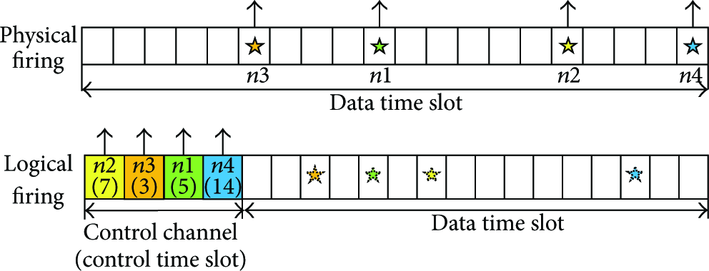
Physical and logical firing signals.
3.1. Frame Structure for Multihop DESYNC
We propose a frame structure for multihop DESYNC, as shown in Figure3. Each frame consists of a control channel and a data channel. The numbers of control time slots and data time slots are C and D, respectively. Each node occupies a control time slot and uses the same control time slot in subsequent frames. The node broadcasts its own firing information and its one-hop neighbor node's firing information through the firing message transmitted in the allocated control time slot. Thus, the neighboring nodes are able to completely update their two-hop neighbors' firing-phase information. Through this firing message, each node can update its firing phase and allocate the data time slots. Two successive frames are needed to update the complete two-hop neighbors' firing-phase information. Thus, the two frames are separated with an odd and even frame, which creates a super-frame.

Proposed frame structure.
3.2. Firing Message Structure
A frame is divided into a control channel and a data channel, where the number of control slots in a control channel is C and the number of data slots in a data channel is D. A single control slot carries a firing message, which is partitioned into a control-slot information area and a firing-phase information area, as shown in Figure4. The control-slot information area consists of C consecutive Node ID-Hop Information (N-H) pair fields. The Node ID subfield is an unsigned integer that identifies the node and the Hop Information subfield is a one-bit unsigned integer that identifies the hop-count of the corresponding node (0: itself, 1: one-hop). Each node writes the control-slot information of both one-hop neighboring nodes and itself in the control-slot information area of its own firing message. For example, if node 5 succeeds in occupying the third control time slot, it records its own Node ID and Hop Information (5, 0) in the third N-H pair of the control-slot information area.

Proposed firing message structure of node 5.
In addition, each node writes the information of its one-hop neighboring nodes in the N-H field, where the order of the N-H field of a one-hop neighboring node in the control-slot information area is the same as the order of the control time slot occupied by the corresponding one-hop neighboring node. This frame structure and operational procedure enable each node to recognize the information about the control-slot occupation of the two-hop neighboring nodes and help a node newly joining the network to avoid possible collisions when occupying a control slot. For example, if nodes 1 and 2, which are node 5's neighboring nodes, occupy the second and fourth control time slots, respectively, the second and fourth N-H fields of the control-slot information area of node 5's firing message are set to (1, 1) and (2, 1), respectively, as shown in Figure4.
Similar to the control-slot information area, the firing-phase information area consists of D consecutive N-H pair fields. Each node records the firing-phase information of both one-hop neighboring nodes and itself in the firing-phase information area. For example, if the firing phase of node 5 is 4, node 5 records its own Node ID and Hop Information (5, 0) in the fourth N-H pair of the control-slot information area. Further, each node writes the firing-phase information of its neighboring nodes in the firing-phase information area of its firing message, so each node can acquire the firing-phase information of the two-hop neighboring nodes. For example, suppose that nodes 1 and 2 are neighboring nodes of node 5 and their firing phases are 5 and 2, respectively. Then, node 5 writes its neighboring nodes' firing-phase information ((1, 1) and (2, 1)) in the fifth and second N-H fields of the firing-phase slots information area, respectively; this is shown in Figure4. Each node transmits the firing message firing-phase information for itself and its one-hop neighbors so each node can recognize the firing phases of its one- and two-hop neighbors, and the hidden-node problem in multihop networks can be resolved.
3.3. Operating Procedure of Multihop DESYNC
The operating procedure of the proposed multihop DESYNC algorithm is as follows: (1) control time-slot allocation, (2) firing-phase allocation and update, and (3) data time-slot allocation, as shown in Figure5. This section explains each of these three subprocedures.

Logical firing flow chart.
3.3.1. Control Time-Slot Allocation
(1) Initial Control Time-Slot Allocation Process. A new node entering the existing network listens to the firing messages in the super-frame. Thus, the node can detect the control time-slot information for all one- and two-hop neighbors. Then, the node randomly chooses a control time slot that is not occupied by its one- and two-hop neighboring nodes. In the odd subframe, each node transmits its firing message through a preoccupied control time slot. Once a node succeeds in occupying a control time slot, it uses the same control time slot in every following frame.
Figure6 shows a collision example for control time-slot allocation when

Example of control time-slot collisions.
(2) Control Time-Slot Collision Detection. Each node can detect a control time-slot collision through the firing messages received from its neighboring nodes. If a node successfully occupies a control time slot and transmits its firing message, the neighboring nodes record its control-slot information (Node ID and Hop Information) in the control-slot information area of their firing messages, as shown in Figure6(b). However, if the control time-slot allocation conflicts, the neighboring nodes do not record the node's control-slot information, as shown in Figures6(c) and6(d). To summarize, a node can determine whether its control time-slot occupation succeeds by checking the existence of N-H fields for itself in the control-slot information area of the neighboring nodes' firing messages.
(3) Control Time-Slot Collision Detection Types
(a) Detecting a Collision in the Same Frame. If nodes
(b) Detecting a Collision in the Next Frame. If nodes
3.3.2. Firing-Phase Time-Slot Allocation and Update
(1) Initial Firing-Phase Time-Slot Allocation Process. After each node succeeds in occupying a control time slot, it can know the allocated firing-phase time-slot information for all one- and two-hop neighbors. Each node randomly chooses a firing-phase time slot that is not occupied by its one- and two-hop neighboring nodes. If two or more nodes choose the same firing-phase time slot, the firing message collision occurs in terms of the logical mean. Figure7 shows a collision example during the firing-phase slot allocation when

Example of firing-phase time-slot collisions.
(2) Firing-Phase Time-Slot Update Process. The firing-phase information of the node is transmitted in the next super-frame. We define the firing phase of node i in the nth super-frame as

A node updates the firing-phase time slot in the (
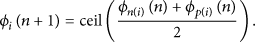
In other words, node i updates the firing-phase time slot at the midpoint between the events of the right firing-phase reference (
(3) Firing-Phase Time-Slot Collision Detection. Each node can detect a firing-phase time-slot collision through the firing messages received from its neighboring nodes. If a node successfully occupies a firing-phase time slot, the neighboring nodes record its firing-phase information (Node ID and Hop Information) in the corresponding area of their firing message, as shown in Figure7(b). However, if a firing-phase time-slot occupation conflicts, the neighboring nodes do not record the node's firing-phase information, as shown in Figures7(c) and7(d). To summarize, a node can determine whether its firing-phase slot occupation succeeds by checking the existence of N-H fields for itself in the firing-phase slot information area of the neighbor nodes' firing message.
(4) Detection Type of the Firing-Phase Time-Slot Collision. Similar to the control time-slot collision detection, there are two types of logical firing-phase time-slot collision detection. In other words, if the control time-slot allocation of two nodes with colliding firing-phase time slots is located in advance of the neighbor nodes' control time slot, the neighbor node does not include the firing-phase time-slot allocation information of these two nodes in the same frame; thus, the two nodes can detect a collision in the same frame. Otherwise, they will detect the collisions in the next frame.
If the control time-slot allocation of a node that detects the firing-phase time-slot collisions is located in advance of the control time slot of the colliding firing-phase nodes, the neighbor node does not include the firing-phase time-slot allocation information of these two nodes in the next frame, allowing the two nodes to detect a collision in the next frame. This is to prevent data time-slot collisions due to firing-phase time-slot collisions. Then, the colliding nodes will choose a firing-phase time slot again in the next frame.
3.3.3. Data Time-Slot Allocation
Each node independently determines the number of data time slots in each super-frame. Each node calculates the midpoint between the events of the left firing-phase reference (
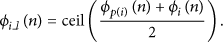
Each node also calculates the midpoint of the event of its own firing-phase time slot (

Node i occupies the data time slots between
4. Simulation
In this section, we perform a simulation that verifies that the multihop DESYNC algorithm works well in multihop networks. Every node in the cycle graph has a degree of 2, as shown in Figure8 on the left. Moreover, every node has the same transmission range, and each node has symmetric connectivity in the unit-disk graph, as shown in Figure8 on the right.

Network topology.
4.1. Performance Evaluation in Cycle Graph
4.1.1. Simulation Parameters
In the cycle graph (
4.1.2. Simulation Results
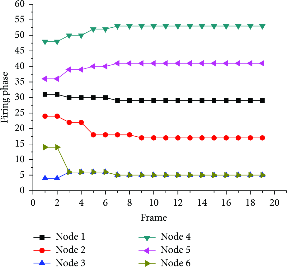
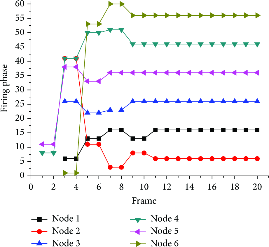
The simulation results showed four desynchronized configurations for the cycle graph, as shown in Figures9,10,11, and12. In the first configuration, shown in Figure9, the firing phases of two nodes that are two hops away from each other converge to the same phases; there are three such phase clusters among the six nodes. This configuration represents the best case in terms of the data time-slot reuse factor. This case results from consecutively allocating initial firing-phase time slots, as shown in Figure9. In this case, each firing-phase cluster of the two nodes ultimately updates to the same firing phase.

Simulation results 1 in the cycle graph.

Simulation results 2 in the cycle graph.
Simulation results 3 in the cycle graph.
Simulation results 4 in the cycle graph.
The second configuration is shown in Figure10. Here, the firing-phase time slots of all nodes converge to one of four phase clusters, each of which includes either one or two firing phases. As a result, each node is allocated five data time slots in every frame. The third configuration is shown in Figure11. Here, the firing-phase time slots of all nodes converge to one of five phase clusters. In this case, each node is allocated four data time slots in every frame. The fourth configuration is shown in Figure12. Here, the firing-phase time slots of each node converge to six different firing phases. This configuration represents the worst-case scenario in terms of the data time-slot reuse factor.
4.2. Performance Evaluation in the Unit-Disk Graph
4.2.1. Simulation Parameters
We evaluate the performance of the proposed multihop DESYNC algorithm compared to CSMA/CA in the unit-disk graph. The simulation parameters are shown in Table1. Ad hoc on-demand distance vector (AODV) routing is used to decide the routing path, and the normalized throughput performance, which is the ratio of the total throughput across all given paths over the number of paths, is obtained.
Simulation parameters.

4.2.2. Simulation Results
Figure13 shows the simulation results of node 1's allocated data slots and its one- and two-hop neighbor nodes when each node's firing phase is desynchronized. Node 1 is allocated the fifteenth to seventeenth data time slots, and we can verify that the hidden-node problem is solved by observing that no duplicate data time slot is allocated within the two-hop neighboring nodes. From the point of view of node 1, the node pairs (33, 3), (26, 15), (26, 25), (19, 25), (19, 18), (11, 28), and (11, 13) are allocated the duplicate data time slots. However, this simply means reusing the channels, because the node pairs are far more than two hops from each other, as shown in Figure8.

Example of the data time-slot allocation in a unit-disk graph.
Let

Reuse-gain results.
The normalized throughput results are shown in Figure15. The multihop DESYNC algorithm achieves better performance than the CSMA/CA algorithm in terms of the normalized throughput. Both methods show degradation of normalized throughput as the number of paths increases. However, the result shows that the throughput of the proposed multihop DESYNC is better than that of CSMA/CA.

Normalized throughput.
5. Conclusion
In this paper, we proposed a multihop DESYNC algorithm that is a bioinspired TDMA-based distributed resource-allocation scheme for IoT networks. We proposed a frame structure and an operating procedure to solve the hidden-node problem. A firing message is transmitted via a control channel; this increases the reliability of the data transmission, as each node is able to share the two-hop neighboring node's firing-phase information with its neighbor nodes. In addition, it was verified that the proposed algorithm could efficiently resolve two different types of collision: control-channel allocation and data-channel allocation. Simulation results showed that multihop DESYNC can effectively resolve the hidden-node problem, and the throughput performance of the proposed multihop DESYNC is better than that of CSMA/CA.
In the contention-free based resource-allocation algorithms such as TDMA, control overhead is inevitable in every frame in order to forward control information necessary for resource management. If the node density is high in a multihop network and the number of neighboring nodes increases, then the greater amount of control overhead is required, which results in deterioration of bandwidth usage efficiency [21]. In order to solve these problems, we have a plan to research the method to reduce the control overhead by considering the activity of nodes and the traffic on/off to make opportunistic resource allocation. Also, we will consider the loss of firing phases owing to mobility and link in future work.
Footnotes
Competing Interests
The authors declare that they have no competing interests.
Acknowledgments
This research was supported by the Agency for Defense Development (ADD-IBR-245) and partially supported by the Chung-Ang University Excellent Student Scholarship in 2014.