
Abstract
With apparent advantages of several GHz license-free spectra, low power consumption, low-cost implementation of CMOS devices, and so forth, 60 GHz wireless communication technology becomes the first choice for short-range high rate wireless communication in future wireless personal area network (WPAN) and wireless local area network (WLAN). While different from common WPAN system with omnidirectional communication, 60 GHz-WPAN system generally adopts directional communication. In this paper, a device (DEV) interconnected mechanism of 60 GHz-WPAN based on switched beamforming technology is structured firstly. Without considering the directional transmission characteristic of 60 GHz communication, most of the 60 GHz-WPAN Medium Access Control (MAC) protocols fail to make full use of the high spatial reuse degree caused by directional communication. In this paper, an average time slot multiplexing allocation (ATSMA) algorithm based on space/time division multiple access (STDMA) solution is proposed, which allows concurrent transmission in a single time slot. The designed link schedule process includes common channel interference (CCI) probing scheme, link coexistence determination scheme, and link schedule algorithm. Extensive simulations are conducted in order to demonstrate the efficiency of proposed scheme. Simulation results demonstrated that the capacity gain is obvious using ATSMA algorithm, no matter whether under omnidirectional antenna or under directional antenna.
1. Introduction
With the increasing production of full-HD even Ultra-HD film and television programs, the wireless communication demand with high transmission rate and low latency experience has become especially urgent. Unfortunately, due to the limitations of spectrum resource, transmitting power, and technical standard, Wi-Fi, UWB, and other short-range wireless communication technologies could not achieve Gbps transmission rate [1–3]. The fifth generation of mobile communication technology is now under brewing and researching, which is a general tendency for using higher frequencies [4–6]. With apparent advantages of several GHz license-free spectra, low power consumption, low-cost implementation of CMOS devices, and so forth [7–10], 60 GHz wireless communication technology has become the first choice for Gbps level short-range wireless communication. At the same time, some researches about 60 GHz wireless communication have been proceeded in wireless sensor network field. A three-element distributed phased array is prototyped based on 60 GHz wireless sensor in [11] to achieve phase-frequency synchronization among physically isolated sensors network. Paper [12] reports the first experimental results on the prototype for a novel wireless sensor network that offers both data collection and localization capability with 60 GHz frequency band. These motivations have mobilized the effort of several standardization groups such as the IEEE 802.15 Task Group 3c (802.15.3c) [13], ECMA387 [14], and IEEE802.11ad [15]. Recently IEEE 802.15.3c has been formed to develop a 60 GHz mmWave wireless personal area network (WPAN) standard including physical layer MAC layer. This standard has now become one of the most mature 60 GHz standards. And the expected physical data transfer rate could reach 5.7 Gbps with this standard.
In the traditional WPAN center-based network, central node is the only data forwarder and only one link (uplink or downlink) is allowed in one time slot. Traditional WPAN media access control (MAC) mechanism usually adopts time division multiple access (TDMA) [16–18], while 60 GHz-WPAN system adopts a hybrid network architecture which combines central-control with peer-to-peer connection. The central node is only responsible for network control and management and the data transmissions without going through the central node. Due to the large propagation attenuation of 60 GHz signal, the interference between the two distant 60 GHz devices is small. In order to remedy the high propagation attenuation, directional transmission based on array antenna beamforming technology is almost essential for 60 GHz communication. Due to directional transmission, about 99.9% of the energy is concentrated in 4.7° beam range [9]. The interference in different directions will be small, which is conducive to directional spatial multiplexing for devices. TDMA multiple access method is not the best multiple access method for directional high-speed communication [19]. Space division multiple access (SDMA) could combine with TDMA and the WPAN system capacity could be improved [1, 20, 21]. In order to take advantage of the characteristic of directional transmission, the MAC mechanism for 60 GHz wireless communication should be designed different from the MAC mechanism of low band, such as Wi-Fi at 2.4 GHz and 5 GHz. However, few 60 GHz multiple access schemes including 802.15.3c standard use this characteristic of 60 GHz at this stage besides [22, 23].
In this paper, in order to realize quick free switch between two communication devices (DEVs) of WPAN system, an interconnected mechanism based on switched beamforming technology is structured firstly. The rationale of spatial reuse in 60 GHz-WPAN system is presented. In order to improve the efficiency of spatial reuse, an average time slot multiplexing allocation (ATSMA) algorithm based on space/time division multiple access (STDMA) solution is proposed. According to this algorithm, resource management and link scheduling are carried out in 60 GHz-WPAN system.
The main contributions of the paper include two parts. Firstly, a DEV interconnected mechanism of 60 GHz-WPAN system based on switched beam code is proposed and 60 GHz-WPAN system model is established based on switch beam, which guarantees free switching between the devices under directional communication. Secondly, the multiple access solution under 802.15.3c standard is improved. SDMA is inserted into the 802.15.3c standard. An ATSMA algorithm is presented which uses the spatial characteristic of 60 GHz signal effectively. Under the premise of certain time slot allocation fairness, the ATSMA algorithm improves the capacity of the 60 GHz-WPAN system significantly.
The organization of the paper is as follows: Section 2 introduces the characteristics of 60 GHz communication, the directional 60 GHz transmission system, and the MAC protocol by 802.15.3c. In Section 3 the 60 GHz-WPAN system model based on switch beam is established; meanwhile, a devices-interconnected mechanism could realize quick free switch between two devices of 60 GHz-WPAN system. Section 4 presents the rationale of spatial reuse in 60 GHz-WPAN. Section 5 presents the judgment method of link coexistence and proposes ATSMA link scheduling algorithm. Section 6 lists the simulation setup and parameters. On this basis, simulation results are presented. Finally Section 7 concludes this paper and marks the potential future works.
2. Characteristics of 60 GHz Wireless Communications
2.1. Characteristics of 60 GHz Signal
60 GHz signal belongs to millimeter wave band. The wavelength of 60 GHz signal is much shorter than mobile communication signal and Wi-Fi signal. 60 GHz wireless communication occupies up to 7 GHz of unlicensed spectrum, which is sufficient for future high rate communication system. The propagation attenuation in millimeter wave band is much larger than low frequency. Friis free space propagation [24] formula explains the reason of high path loss for 60 GHz signal. Consider

The average transmitting power and receiving power are denoted as
2.2. Directional Transmission Based on Switched Antenna Array
Since 60 GHz signal suffers large propagation attenuation in the process of transmission, some methods should be carried out to avoid the waste of energy. For 60 GHz communication, only 5 mm wavelength makes it feasible to integrate a large number of antenna elements on the whole package for both 60 GHz transmitter and receiver [25]. Antenna array beamforming technology is preferred for 60 GHz wireless communication because of the large antenna gain, small size, and fast electronic steerability. The antenna array beamforming provides directional transmission, which can overcome the high path loss problem. The antenna array beamforming is also conducive to directionality spatial multiplexing and improves the system capacity. At the same time, the antenna array beamforming is especially meaningful in solving the notable NLOS obstruction problem.
Generally, smart antenna beamforming technology involves switching beamforming and adaptive beamforming [26]. Currently, 60 GHz communication systems commonly adopt switching beamforming based on beam code due to the low complexity [9]. Switching beamforming is a method which divides user area into multiple narrow beam partitions. Each of partitions corresponds to a fixed beam, whose weight vector is preconfigured by the system. By beam training or position estimation of the target user, antenna array can select and switch optional weight vector. Two 60 GHz wireless communication standards which are proposed by IEEE802.15.3c and 802.11ad adopt switching beamforming to compensate high path loss and overcome link block. 802.15.3c even has provided the designing scheme of beam code and beam training mechanism [9].
2.3. 60 GHz MAC Protocol by 802.15.3c
According to IEEE 802.15.3c, the channel access and data transmission are based on the superframe structure [9], which is composed of three parts: Beacon Period (Beacon), the controller broadcasts commands and access information by sending the beacon frame; Competitive Access Period (CAP), this is a contention-based channel access period, adopting Carrier Sense Multiple Access/Collision Avoidance (CSMA/CA) scheme; and Channel Time Allocation Period (CTAP), the channel access mechanism is based on TDMA mode. PNC divides CTAP into several channel time allocations (CTAs). The length of a superframe can be set to a fixed value or a variable according to specific requirements. Considering the application of beamforming technology for directional transmission, two structures are presented, which are superframe under omnidirectional antenna pattern and superframe under quasi-omnidirectional antenna pattern. The major difference is that the beacon frame will be sent in different directions in turn to make sure that all devices can get access to the network in the latter pattern. Figure 1 presents the quasi-omnidirectional antenna pattern superframe architecture by 802.15.3c.

The superframe architecture of quasi-omnidirectional antenna pattern by 802.15.3c.
3. 60 GHz-WPAN System and Devices-Interconnected Mechanism
IEEE 802.15.3c standard builds the network by using the piconet as its basic unit, which is a collection of all devices connected together. To support self-organized network, all devices are equal with the same priority and could communicate with each other. Devices are divided into piconet controller (PNC) and common DEV, where PNC is responsible for managing the whole network, including timing management, resource allocation, and task scheduling. In order to ensure the self-organization and robustness of the network, PNC is dynamically selected from network nodes and supports seamless switching between devices when the former PNC suddenly leaves or fails to work.
Generally, WPAN system supports intercommunicate between any two DEVs. For common WPAN system, omnidirectional antennas are equipped by all DEVs. No matter the receiving DEV located in any orientation of sending DEV, the signal always could be received. 60 GHz system generally adopts directional communication. If every DEV always points to fixed direction in the whole communication process, it is apparently unable to realize intercommunication for 60 GHz-WPAN. At this point, array antenna beamforming technology will become the preferred technology for 60 GHz-WPAN. In order to reduce the complexity of building networks, switching beamforming based on beam code is adopted.
As shown in Figure 2, there are N DEVs in the WPAN, each of them purchasing an antenna array to achieve directivity control. We select DEV1 as PNC and conduct beam training based on 802.15.3c beam code under unobstructed environment [9]. After beam training, the interconnecting optimal beam pairs of devices are found and the antenna weight vectors corresponding to these optimal beam pairs are recorded, as shown in Table 1.
Antenna weight vectors record form of interconnecting DEVs beam pairs.


Schematic diagram of 60 GHz-WPAN link transmission in superframe-i.
Assume that, in superframe-i, 3 pairs of link send out transmission request in this superframe, which is links DEV1-DEV2, DEV3-DEV6, and DEV5-DEV7, respectively. At the beginning of communication, weight vectors
In the next superframe-

Schematic diagram of 60 GHz-WPAN link transmission in superframe-
Through establishing a weighted vector form of interconnection beam pairs for WPAN DEVs, a DEV interconnection mechanism based on the beam code for 60 GHz-WPAN is set up. This mechanism can help to realize fast free switch for every communication DEV. On one hand, it is satisfied for the directional transmission of links; on the other hand, it is also convenient for switching the communication DEVs. The spatial reuse characteristic of 60 GHz-WPAN will be investigated based on directional transmission mechanism in the following sections.
4. Spatial Reuse Rationale for 60 GHz-WPAN
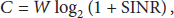
As shown in formula (2), Shannon theorem indicates the channel capacity in continuous channel under Gaussian white noise, namely, the maximum theoretical transmission rate:

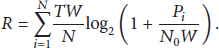
For STDMA link allocation, each link can share time slot with other communicating links concurrently according to certain criteria. Assuming link i can be allocated to 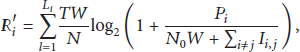

From ((3), (5)) and ((4), (6)), to ensure spatial multiplexing gain of the single link i or the whole WPAN system,
5. Link Coexistence Determination and ATSMA Link Scheduling Algorithm
When adopting STDMA, the capacity of WPAN system is mainly decided by interference power
Paper [23] proposed a Virtual Time Slot Allocation (VTSA) algorithm based on the MAC design of IEEE 802.15.3c. A Probing Signal Broadcasting Period (PSBP) is added in the front of CTAP to measure the mutual interference between links in the same superframe. After getting the information of mutual interference between links, PNC will allocate virtual time slot for the remaining links. However, VTSA algorithm neglects the effect of noise during the decision process of coexistence and does not consider the effect of directional antenna for spatial multiplexing. So in this section, an average time slot multiplexing allocation (ATSMA) based on STDMA solution is proposed. We reference the ideas of establishing common channel interference (CCI) table by VTSA algorithm and set up a link interference tolerance (LIT) table which is used to calculate the link interference upper limit under different transmission rate. The actual link interference in CCI table is compared with the interference tolerance of this link in LIT table, in order to determine whether two or more links could coexist. At the same time the utilization rate of each CTA time slot is maximized on the premise of slot allocation fairness and the WPAN system capacity is improved as much as possible.
5.1. The Common Channel Interference (CCI) Probing Scheme
In proposed ATSMA algorithm, a PSBP is also added in front of CTAP for every frame. During this period, PNC receives communication request and records link number N firstly. Each link is scheduled by PNC to send a short probing signal in their own transmission direction in sequence. Meanwhile, other links receive and record the signal in their own transmission direction in sequence. Then the receiver of each link records the statistical interference information. PNC establishes a CCI table. The CCI measurement data will be employed for CTAP of this frame. If there are N links with communication request, the CCI table will be a 

5.2. Link Coexistence Determination
Because the main application of 60 GHz communication is wireless HD video transmission, which proposes higher request for the stability of transmission rate, each transmission link should make stable and reliable transmission rate as the basic requirements. So, under specific modulation and coding scheme, the condition of link coexistence determination is set to be that the mutual interference between links does not affect the required transmission rate of this link. That is to say, the SINR of receiver must satisfy certain condition; we set the condition as 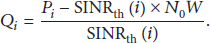
5.3. ATSMA Link Schedule Algorithm
After the process of establishing CCI table and LIT table, PNC allocates time slot to each link according to certain algorithm. Based on the MAC standard of IEEE 802.15.3c, we proposed an efficient scheduling algorithm ATSMA for 60 GHz-WPAN communication system. System capacity is an important criterion to evaluate a time slot allocation algorithm; meanwhile the fairness of link allocation also should be considered. Each link is guaranteed to be accessed in one frame. ATSMA algorithm could maximize the utilization rate of each CTA on the premise of slot allocation fairness and as much as possible improve the WPAN system capacity. Figure 4 presents the flowchart of ATSMA algorithm.

ATSMA algorithm flowchart.
The basic process of ATSMA algorithm is as follows:
The CTAP is divided into N CTAs by PNC, and PNC allocates each CTA to each link with TDMA scheme in proper order. Furthermore, link i ( For Change the value of i as
In order to guarantee more links could share the same time slot, link with smaller CCI value is firstly allocated to the
6. Simulation Result and Performance Analysis
After the link scheduling algorithm is confirmed, system performance evaluation and simulation are carried out.
6.1. Simulation Environment
(1) Antenna Model. Assume that all devices in 60 GHz-WPAN system are deployed with the same antenna equipment. Two antenna patterns are taken into consideration, which are omnidirectional antenna and directional antenna with switching beam. 802.15.3c beam codebook is used to structure switching beam. The number of antennas in antenna array is 8 and the number of beam is 16.
(2) Spatial Distribution Model of 60 GHz-WPAN System. Wireless 60 GHz nodes are randomly distributed in the 10 m × 10 m indoor square area. Assume that there are 5, 10, and 20 links (namely, 10, 20, and 40 nodes) having transmission request in one superframe. The transmitting power of each node is 10 dBm. Considering that the antenna gain of omnidirectional antenna in 60 GHz system could not support long range communication, the distance between transmitting node and receiving node with omnidirectional antenna will be set to be less than 4 m in order to ensure the required SINR for stable transmission. Due to the directional antenna gain being big enough for compensating the high path loss, the transmitting node and receiving node of each link with directional antenna are randomly selected from 10 m × 10 m indoor square area. Assume that all the nodes in communication status do not block other nodes in space. According to the piconet structure, PNC is randomly selected from the nodes and is responsible for peer-to-peer communication management and time slot allocation. In order to avoid the accidental effect caused by the position of nodes, 1000 times simulations with different random seeds are proceeded and the average capacity is calculated.
(3) Channel Model. IEEE 802.15.3c channel model is adopted [27], which is constructed by the measurement of 60 GHz signal propagation characteristics. Simulations are conducted in indoor living environment LOS channel CM1.
(4) MAC and PHY Layer Parameters. Since different modulation and coding schemes may be adopted by different links in actual WPAN system, we set three kinds of links which adopt different 60 GHz OFDM schemes, MCS1, MCS2, and MCS3, respectively. The percentages of three kinds of links are 40%, 40%, and 20%, respectively. Specific parameter setting is shown in Tables 2 and 3.
OFDM modulation and coding parameters.

MAC and PHY layer parameters.

(5) The Selection of Gaussian White Noise Level. Generally, Gaussian white noise can be calculated by NF = KTBF, where F is the noise factor, which is defined as
6.2. Simulation Result and Performance Analysis
System capacity is selected as the evaluation criteria to verify the validity of this algorithm. TDMA scheme and ER theory scheduling scheme based on STDMA multiple access are adopted to contrast the proposed ATSMA algorithm.
Figure 5 presents the 60 GHz-WPAN system capacity using different link scheduling schemes in one superframe under omnidirectional antenna. Since the selected noise levels meet the minimum SINR requirement under certain transmission rate, so the system capacity does not change with the noise level if TDMA is adopted as the time slot allocation scheme. The system capacity of TDMA scheme is about 21 Mb in one superframe. When the system noise level is low (−94 dBm~−80 dBm), the system capacity based on ER theory scheduling scheme will not change with the increase of noise level and also will not change with the increase of link number. The system capacity based ER theory is equal to the system capacity of TDMA scheme when the system noise level is low. This is because the ER radius is larger than the longest distance of room model (diagonal distance). When the noise level is −94 dBm~−80 dBm, all the links are judged which cannot coexist for parallel transmission. The ER theory radius decreases with the increase of noise. When the noise level is greater than −80 dBm, the links which can coexist for parallel transmission begin to increase and system capacity also begins to increase. ER theory scheduling scheme gradually presents the effect of spatial reuse, and the increasing trend of capacity caused by spatial reuse is greater than the decreasing trend of capacity caused by noise. The total system capacity in one superframe also presents increasing trend with the increasing of links number. This is because the links falling into ER region are increasing with the increasing of links number. The links for parallel transmission will also increase. For ER theory scheduling scheme, at most 1.31-fold, 1.42-fold, and 1.52-fold of capacities can be achieved compared with TDMA when the numbers of links are 5, 10, and 20, respectively. No matter how many links exist in WPAN system, the reuse performance and system capacity will decrease when noise level is greater than a certain value. This is because the decreasing trend of capacity caused by noise is greater than the increasing trend of capacity caused by spatial reuse. For ATSMA link scheduling algorithm, system capacity is greatly improved comparing with ER theory scheduling scheme and TDMA scheme when the noise level is relatively low. At most 2.11-fold, 2.72-fold, and 3.15-fold of capacities can be achieved compared with TDMA when the numbers of links are 5, 10, and 20, respectively. This is because the probability that links are arranged to transmit concurrently in the same CTA increases as the link increases. Furthermore the system capacity will increase. Because the interference tolerance of each link is fixed, less link mutual interference can be allowed with higher noise level. Therefore, the system capacity will decrease as the noise level increases. When the noise level is much lower than the link mutual interference, the negative effect of background noise is small. So the decreasing trend of capacity is not obvious in the range of −94 dBm~−85 dBm. Although the decreasing trend of ATSMA algorithm is accelerated when the noise level is higher, obvious improvement still can be achieved over ER theory scheduling scheme. Simulation also presents that the system capacity will not increase linearly as the links number increases.

60 GHz-WPAN system capacity with different link scheduling schemes in one superframe under omnidirectional antenna.
Figure 6 presents the system capacity of 60 GHz-WPAN in one superframe using different link scheduling schemes under directional antenna. Similar trend is presented with omnidirectional antenna. The system capacity of TDMA scheme is also about 21 Mb in one superframe. For ER theory scheduling scheme, at most 3.6-fold, 6.6-fold, and 8.2-fold of capacities are achieved comparing with TDMA when the numbers of links are 5, 10, and 20, respectively. For ATSMA link scheduling algorithm, at most 4.4-fold, 8.3-fold, and 14.7-fold of capacities are achieved comparing with TDMA when the numbers of links are 5, 10, and 20, respectively. For directional antenna system, the performance of ATSMA algorithm is still superior to ER theory scheduling scheme and TDMA; meanwhile, the advantage become more obvious when there are more links in the system. Comparing with omnidirectional antenna mode, the system capacity presents the increasing trend when the noise level is low (−94 dBm~−80 dBm). The multiplexing gain caused by directional transmission is significantly increased comparing with omnidirectional antenna whether adopting ATSMA algorithm or ER theory scheduling scheme. This also verifies the high spatial reuse character of 60 GHz signal under directional transmission. Although the complexity of ATSMA algorithm is a little bit higher than ER theory scheduling scheme (an extra PSBP needs to be established and the link mutual interference needs to be measured), the capacity gain is obvious, no matter whether under omnidirectional or directional antenna.

60 GHz-WPAN system capacity with different link scheduling schemes in one superframe under directional antenna.
7. Conclusion
This paper proposes a DEV interconnected mechanism of 60 GHz-WPAN system based on switched beam code, which guarantees free switching between the devices under directional transmission. Then the multiuser access solution under 802.15.3c standard is improved using the directional transmission mechanism. SDMA is inserted into the 802.15.3c multiuser access solution. An ATSMA algorithm based on STDMA solution is proposed. With the premise of certain time slot allocation fairness, ATSMA algorithm utilizes the spatial characteristic of 60 GHz signal effectively and improves the capacity of 60 GHz-WPAN system significantly. The simulation results indicate that the multiplexing gain caused by directional transmission is significantly increased comparing with omnidirectional antenna based on STDMA scheme.
Due to the large material penetration loss of 60 GHz signal, 60 GHz communication link is prone to be interrupted by blocking. How to achieve high system throughput, meanwhile solving the link blocking problem, is a new challenge [28–30]. Constructing collaboration WPAN antiblocking communication model and redesigning the link scheduling algorithms are our next work.
Footnotes
Conflict of Interests
The authors declare that there is no conflict of interests regarding the publication of this paper.
Acknowledgments
This work was supported by National Natural Science Foundation of China (no. 61304222), China Postdoctoral Science Foundation (2014M551905), Natural Science Foundation of Shandong Province (no. ZR2012FQ021), Open project of State Key Laboratory of Millimeter Waves (no. K201321), Shandong Province Postdoctoral special funds for innovation projects (128761), Shandong Province Outstanding Young Scientist Award Fund (2014BSE28032), and the Fundamental Research Funds for the Central Universities under Grant no. 14CX02139A.