
Abstract
Demand response (DR) is a major contributor to grid stabilization during peak times. As the scope and functions of DR increase, DR participation of residential customers has attracted great attention. The main issue of DR design for the residential sector is to build an integrated network for exchange of DR signals between the utility operator and home users who want to participate in DR services at various locations. In this paper, we introduce an automated residential DR model based on advanced metering infrastructure (AMI) network. The internationally recognized standard protocol, known as the open automated demand response version 2.0 (OpenADR 2.0), is applied to realize a fully automated DR (ADR). In order to utilize existing AMI devices as ADR resources, the smart meter is modified while retaining current structure and functions, and various ADR devices are developed based on OpenADR 2.0 protocol. Simulation and demonstration tests are conducted to confirm conformance of the protocol and to verify load variations of home appliances under our ADR model. The developed software programs have obtained an international certification from the OpenADR Alliance.
1. Introduction
The power shortage issue happens a lot during times of peak demand, and the power system frequency drops below its nominal value when the system loses its ability to supply power. This frequency deviation causes tragic damage events, such as blackouts. Demand response (DR) is a mechanism to achieve grid stabilization via control of customer loads [1, 2]. It allows customers to reduce their electricity usage over a given time period or to shift that usage to another time period in response to utility signals and customer's preference.
Most of the current DR programs aim at commercial and industrial customers as they use a great deal of electricity during peak times [3–5]. As the scope and functions of DR increase, DR participation of residential sectors has attracted significant attention; thus, it has become critical to design and deploy residential DR architecture. In [6–8], the authors showed great potential of DR participation in residential sectors, and the effects are verified in [9, 10]. However, in residential DR system, a central challenge lies in deploying how to construct a network between DR providers and home users who participate in DR services at various locations.
There are two popular DR programs according to how load variations are brought about. Price-based DR program induces customers to make smart decision in response to time-varying prices; for example, end-users can freely shift some power consumption from high-price periods to low-price periods. One example of this type includes the programs provided by Ameren Illinois [11]. Incentive-based DR program is implemented by utilities or aggregators, and they can control the operations and controls of residential appliances in remote areas. It refers to direct load control (DLC), and the program has been implemented by several utilities, for example, [12, 13]. In here, the aggregators are new entities in the electricity market that act as intermediate brokers between the utility company and customers [14]. In the residential DR system, the aggregator instead of the utility operator takes charge of DR providers.
Current residential DR is performed by aggregators, and the aggregators separately contact all home users using passive methods, for example, phone and e-mail. Customers perform energy reduction during promised periods through smart home devices such as home energy management system (HEMS) control electric devices [15, 16]. In addition, existing DR services are operating only in lab or a few buildings within the bounds of confined networks.
But this DR mechanism exhibits several shortcomings. First, when the customer base is large, it is difficult for aggregators to contact all home users. Second, in an emergency case, aggregators cannot attempt DLC because the above DR system does not consider aggregator's connection. Third, the existing DR system lies in the interoperability problem between heterogeneous systems because each system depends on its own specialized control method. Hence, the current DR system is not suitable for residential sectors, and there is no DR system deployment aimed at all home consumers.
In this sense, residential DR should have the capabilities to accommodate all home users, and in order to achieve this requirement, this paper designs integrated network architecture for DR information exchange between aggregators and home users. These DR nodes can share DR signals through the network. As a core technology of smart grid, advanced metering infrastructure (AMI) serves as a bridge for providing bidirectional information flow between utility domain and user domain through a meter. The smart meter has designed highly flexible networks architecture that can include different communication media. The AMI network is able to access each individual home in real time which is composed of the same power distribution system. In addition, AMI is gaining acceptance in many countries [17–19], and Korea is also constructing AMI based on power line communication (PLC) technology in [20]. In this paper, we use existing PLC-based AMI network as a DR network resource.
Aggregators use a common information model (CIM), due to the large number of home users. CIM is an open standard that specifies data format and message exchange method and is primarily developed by various international institutes associated with communication technology, for example, ZigBee Alliance, HomePlug Alliance, and OpenADR Alliance. In this paper, we adopt open automated demand response 2.0 (OpenADR 2.0) [21]. The technology is an internationally recognized standard communication protocol and defines a DR interaction based on the CIM between nodes using standard-based IP communications, such as HTTP. Also, it is based on fully automated signaling from DR providers to provide automated connectivity to customer's control system, and at present, some utilities have initiated ADR projects [22].
This paper presents a residential ADR model using PLC-based AMI network, and its architecture is shown in Figure 1. Three data communication domains are classified, a home area network (HAN), a neighborhood area network (NAN), connecting gateways, for example, data concentration unit (DCU) in the electric pole to meters, and a wide area network (WAN), connecting utilities to a set of gateways. The HAN is public domain, and WAN and NAN are private domain managed by the utility. The AMI network largely pertains to NAN domain. In other words, AMI network is the essential communication section that links between utility and homes. The smart meter and the DCU belong to NAN domain. In the work, the usage data of home devices is transferred by the smart meter using PLC, and other communication technologies such as ZigBee and WiFi are available depending on home network configuration.

Residential ADR architecture over AMI network.
Various ADR devices are developed based on OpenADR 2.0 protocol and AMI devices, for example, a smart meter and a data concentration unit (DCU), are modified while retaining current structure and functions to utilize as DR resources. Our proposed residential ADR system guarantees leading to significant benefits through DR participation of home users during peak times and realizes full DR automation. Our contributions can be summarized as follows:
We devise a residential DR model, where all entities exchange DR signals through AMI network. We realize full automation of DR, where all entities operate according to predetermined strategies that are based on OpenADR 2.0 protocol. We obtain an international certification from OpenADR Alliance, where the developed programs satisfy all requirements of OpenADR 2.0 protocol. We guarantee interoperability between heterogeneous DR systems.
The rest of this paper is organized as follows. In Section 2, we introduce AMI network and OpenADR 2.0 profile. The ADR system architecture based on AMI network is proposed in Section 3. In Section 4, we present how ADR devices could be configured in existing AMI systems. The results of the simulation and demonstration tests are given in Section 5. Finally, a conclusion to the paper is presented in Section 6.
2. Related Works
2.1. AMI Network Overview
The role of AMI is to enable two-way communication between utilities and their customers. The utility operator can remotely read real-time energy-related information of home users without the need for passive meter inspection. As stated in Section 1, AMI network consists of a WAN and a NAN. The WAN uses long range and high bandwidth communication technologies, such as cellular and satellite communication, and the NAN typically has shorter range and can access a customer's meter. The network domain is deployed using wireless or PLC technologies, and in Korea, PLC technology is adopted as communication media on the 60 Hz frequency band. PLC loads a high frequency signal in the electric wire and communicates by filtering communication signal using a PLC module or modem. The PLC technology has already been applied in various fields [23, 24], and in particular, it is widely used in the fields of home automation [25, 26]. Korea AMI system is based on KS X ISO/IEC 12139-1 [27], which is an international standard technology ensuring high-speed communication between nodes, and the current AMI is being exported to many countries, such as Ghana, the Republic of South Africa, and Uzbekistan.
In this paper, we focus on the NAN and HAN that use PLC, due to constrained accessibility of the WAN domain. The PLC-based network topology brings about robustness to the network over in-home wiring since communication routes can select an optimal path within the same power distribution line.
2.2. OpenADR 2.0 Profile
The OpenADR 2.0 profile is an application-level data model to facilitate common information exchange messages between DR providers and participants. It is designed to meet the strict communications requirements set for ADR services at customer's locations. The ADR services offer information that is pertinent to DR and pricing. OpenADR 2.0 was developed by the OpenADR Alliance, with certification programs released in 2013, derived from a formal standards development organization. It is currently published by the IEC as a Publicly Available Specification (PAS) [28], and many utility companies are operating various ADR services based on the protocol. All nodes operate over a web service using the hypertext transfer protocol (HTTP) method and express DR signal information using the extensible mark-up language (XML).
The profile level is classified into two types: 2.0a for simple devices and 2.0b for more sophisticated devices. OpenADR 2.0b profile [29] was recently completed, and various functions are appended, for example, report, registration, and poll. The profile uses the terminology of the Virtual Top Node (VTN) and the Virtual End Node (VEN). In an interaction, generally, the VTN acts as the server which provides information to the VEN, and the VEN is regarded as clients which request information from the VTN. Further details of the protocol are specified in [21]. In this paper, we construct an integrated ADR model based on OpenADR 2.0a, and the aggregator can control residential devices directly according to a predetermined strategy that is based on OpenADR 2.0a.
3. ADR System Model
The residential customers can be divided into two types depending on the housing scale and power consumption usage: low-voltage (LV) and high-voltage (HV) customers. Generally, the LV customer dwells in detached houses and the HV customer resides in apartment complexes. In [28], the utility has been replacing an existing analog meter with the smart meter that has a PLC module for PLC in LV customers first. In this paper, our aim is the LV home users that already constructed AMI systems.
The concept of the proposed residential ADR model over PLC-based AMI network is shown in Figure 2. Each home has the smart meter and is connected to the same electric power system. In the AMI network, the DCU and the smart meter use PLC where they have the same built-in PLC chip. The AMI network is divided into two groups: the DCU publishes and transmits information about DR events to the smart meter and the smart meter receives the information. Our model enables home users to participate in DR services, regardless of their location, and utilities can directly control residential electric appliance, such as a thermostat. The core of this model is DR role of AMI devices while retaining current structure and functions.

Residential ADR model over AMI network.
In this work, we designed and developed several devices to perform ADR service, the DR controller (DRC) for the smart meter, the home gateway, and home appliance controller (HAC). In addition, PC-based demand response management server (DRMS) is developed to create DR events based on OpenADR 2.0 protocol and plays a role in a DR server. However, most home appliances are not able to interpret DR signals based on OpenADR 2.0a protocol, and the smart plug is developed to control home appliances. The smart plug performs on/off operation of connected appliances according to a kind of received DR signal, and this allows all electric devices to have DR control without a separate device. Specifically, in order to elaborate control home appliances, the HAC is developed for two home appliances, an air conditioner and a clothes washer. Lastly, the DRC is developed to deal with DR signals between PLC and Internet networks and is embedded in the smart meter.
4. ADR System Design
As noted in Section 2, OpenADR 2.0a protocol operates four-step message exchanges which are oadrRequestEvent, oadrDistributeEvent, oadrCreatedEvent, and oadrResponse. In pull interaction patterns, a client requests events by periodically sending an oadrRequestEvent message. All events are generated in the DR server and sent to interested VENs using the oadrDistributeEvent message containing one or more clients. The details of each message are described in OpenADR 2.0a [21]. All devices ensure security service using public key infrastructure (PKI) certificates and digital certificates issued by a trusted certificate authority. In order to offer a secure Internet connection, information exchanges are accomplished with transport layer security (TLS) version 1.0 encryption.
4.1. Demand Response Management Server (DRMS)
The DRMS is an ADR server operating as a web server and offers DR events to interested clients. We developed a simple ADR server on a laptop computer. The DRMS is embedded in OpenADR 2.0a protocol and is usually located in the aggregator. Figure 3 shows the DRMS configuration with event management database and a graphical user interface (GUI) server. It uses a visual C# development environment, for example, C# builder, and is applied on an Internet information server (IIS), which is a type of commercial web server. Microsoft simple query language (MSSQL) database is used, and the server accesses the database through the language integrated query (LINQ).

DRMS configuration.
The DR event management database is composed of the event properties, DR signals, event intervals, and event matching tables. The former ones include DR event information, that is, event ID, start time, duration, and price level, and the latter is a matching table to start the first event. The event contains one of four levels and operates the DR event according to the determined level. In pull pattern, transaction condition of DR event hinges upon VEN ID information between server and client. If two nodes have the same VEN ID, ADR service proceeds according to predetermined strategies. Otherwise, the server waits for client's request until it receives the same VEN ID.
In order to verify implementation of OpenADR protocol, the developed DRMS performs a validation check about all messages using the document object mode (DOM) library. This library converts a tree-form object and compares all elements with the schema which prescribes the grammar structure of OpenADR 2.0 protocol.
4.2. DCU Reconfiguration and Watt-Hour Meter (WHM)
The DCU is a representative device of AMI system, and it is impossible to arbitrarily alter its structure as it is a standard device as one of the state-owned assets. We developed a watt-hour meter (WHM) which is a GUI program based on Windows-Form library using C# language. The WHM displays current connected smart meter information and sends it to ADR web server.
Figure 4(a) depicts reconfiguration of the DCU structure to support ADR functions. It is composed of four agent, a DRMS agent, sending OpenADR data between the DRMS and the ADR module, a front end processor (FEP), managing the reading data, a reading agent, collecting reading data from the smart meter, and a simple network management protocol (SNMP). Figure 4(b) shows the WHM program, and two smart meters are currently connected to the DCU. The WHM includes the DCU information, the ADR web server information, and the smart meter information. It checks the smart meter address connected to the DCU and converts reading data received from the smart meter into XML-formatted data for a web service. Also, it periodically sends data to the DRMS every 15 minutes using file transfer protocol (FTP). If any smart meter is not connected, it does not display any meter ID.
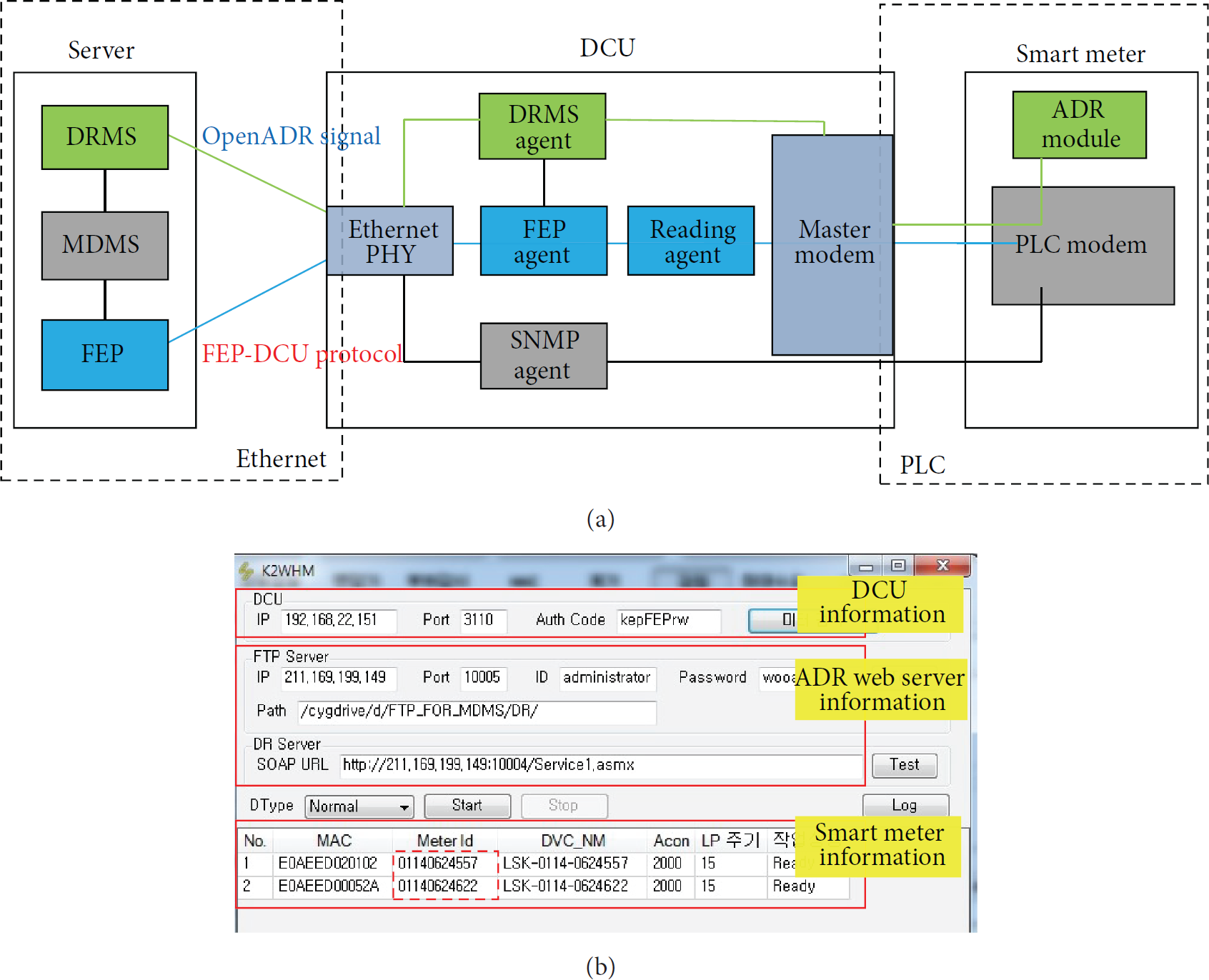
DCU with ADR functions: (a) reconfigured DCU structure and (b) WHM program.
4.3. Demand Response Controller (DRC)
A smart meter is a representative device of AMI system, and it serves as a bridge for connection between utilities domain and user domain. It has basically a PLC module to use a power line, and the module measures total power consumption of load devices. Generally, a smart meter collects reading data which is called load profile (LP) every 15 minutes.
In residential DR, the smart meter plays a major role in connecting an external upper device and deals with DR data based on OpenADR, simultaneously. Just like the DCU, it is impossible for the smart meter to arbitrarily alter its structure, due to a utility-owned asset. With retaining previous function as well as structure, the smart meter must be able to possess the DR ability. Thus, we developed a DR module that allows the smart meter to have DR actions based on OpenADR 2.0a protocol. The DR module communicates with PLC module through media independent interface.
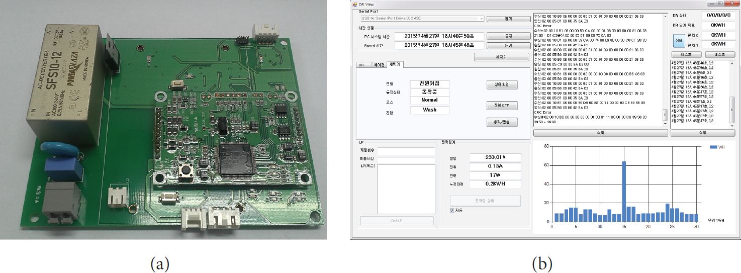
In this paper, we refer to the DRC that is a combination of the PLC and DR modules. Figure 5(a) shows the designed DRC module structure including the PLC and DR modules. The DR module is designed with a removable type to be mounted over existing PLC module, and the coupled module is shown in Figure 5(b). Figure 5(c) represents the smart meter which is inserted in the DRC module. The implemented software that is embedded in the DR module is formally certificated from the OpenADR Alliance and explained in Section 5.3.

(a) DRC module structure, (b) photograph of DRC module for smart meter, and (c) photograph of the smart meter inserted in the DRC module.
4.4. Home Appliance Controller (HAC)
This section aims at advanced DR actions of the home appliance, and HAC is developed to control home appliances, such as an air conditioner and a clothes washer. It controls the home appliance by DR signals received from the smart meter and the gateway. Figure 6(a) shows photograph of the HAC.
(a) Photograph of the HAC and (b) HAC monitor screen.
We defined a common packet structure between the HAC and a home appliance, as shown in Table 1. The STX and ETX fields mean start of text and end of text, respectively. A kind of a DR service is determined by the command field, for example, new DR addition, DR deletion, and the smart meter status request, and the data field represents data matching description between OpenADR 2.0a signals and control signals of the home appliance. Figure 6(b) depicts the information of the home appliance related to current DR events, such as power consumption of the appliance, event information, DR list, and raw data log.
Common packet structure for the home appliance.

We also reconfigured DR levels for the home appliance based on DR levels defined in OpenADR 2.0a protocol, as shown in Table 2. It reflects delay load control for home appliances by defined Association of Home Appliance Manufacturers (AHAM) standards [30]. The DR level of the air conditioner is determined by a certain duty cycle that is calculated in proportion to cumulative power consumption. Particularly, its operation mode changes from cooling mode to blast mode in DR level 3.
Reconfigured DR levels for home appliances.
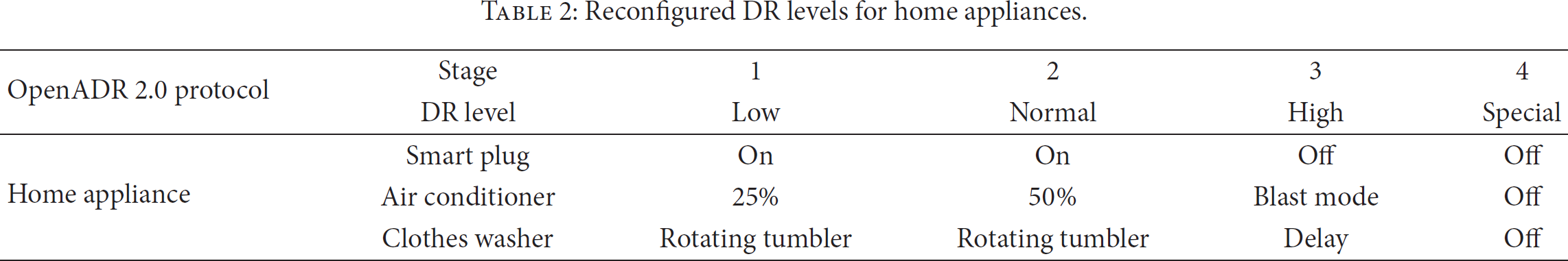
The clothes washer consists of a rotating tumbler and heating coil. The power consumption of the motor part is usually in the range of several hundred watts, for example, 100 watts, while that of the heating coils can be several kilowatts, for example, 3 kW. Thus, load reduction of the clothes washer depends on only rotating tumbler operation in DR duration.
4.5. Smart Plug
This section aims at a basic DR action of all home appliances. As mentioned above, most home appliances do not have any DR controller; thus, they require a separate device, such as HAC, to understand DR signals.
We developed a smart plug to allow electric appliances to have DR actions. It is designed as a socket type to plug in an electric cord of the home appliance. The smart plug cuts off the power according to received DR signals, and then the connected home appliance also shuts off the power automatically. We divided two DR types for on/off operation according to DR levels because OpenADR 2.0a protocol describes four DR levels (e.g., low, normal, high, and special). Considering the above four DR levels, we reconfigured DR levels, and Table 2 represents reconfigured DR levels for a smart plug.
Figure 7(a) shows block diagram of the smart plug, and it has the PLC module and DR module. The smart plug is composed of a communication block, an application block, and a measurement block. The communication block is used for PLC and includes a coupler to separate the communication signal entering from the power line. The measurement block measures the current, voltage, and real and reactive power as well as power factor of the electric devices connected to it and is used to observe load variation of the home appliance. OpenADR 2.0 protocol-related software is implemented in the application block. Communication block and application block ensure high-speed data communication using MII interface. Figure 7(b) shows photograph of the smart plug including the PLC module and DR module.
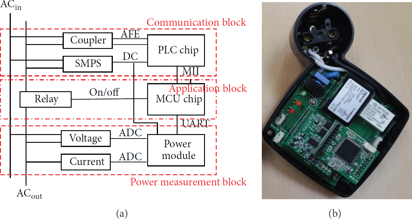
(a) Block diagram of the smart plug and (b) photograph of the smart plug including the PLC and DR modules.
5. Simulation and Demonstration Tests Results
In this section, the concept-proof implementation has been tested on the devices designed in the previous sections. The simulation and demonstration tests are performed to verify conformance of the implemented software and observe the load variations of home appliances under the proposed ADR model.
5.1. Simulation Test Results
A simulation test intends to verify whether the developed ADR devices are embedded in OpenADR 2.0a protocol. Namely, conformance of the protocol is verified through this test. We developed GUI program to visually observe OpenADR messages in detail. Figure 8 represents GUI program, and it is composed of an event list, a properties set, log data, and parsing data. The properties set includes information of the server such as uniform resource locator and polling period. Also, the program conducts a validation check test to verify conformance of OpenADR 2.0a protocol, and the results of the test are recorded in the parsing data. The log data displays ongoing signals, and the former DR records. This program is formally certificated from the OpenADR Alliance and explained in Section 5.3.

GUI program for conformance of OpenADR protocol.
5.2. Demonstration Test Results
A demonstration test is performed to confirm the feasibility of an ADR service under actual residential environments. The test is composed of two DR demo types using AMI network and Internet network. Also, DR services are divided into HAC-based control and smart plug-based control. Figure 9 illustrates the demo scenario among three homes. Aggregator transfers multiple ADR events to three targeting devices according to predetermined strategies.

Demo scenario among multiple homes.
The DCU, the smart meters, and the smart plugs are connected to an identical power line. This configuration shows a typical example of AMI network. The DR server transfers DR signals to the smart meter and the home gateway deployed in each home. This process shows the feasibility of AMI network, regardless of home user's location. Note again that the DR signals are based on OpenADR 2.0a protocol which is encrypted data applying TSL1.0. Each customer participates in DR service for a day. The DR period is from 12 to 16 which is the peak hours of power consumption, and the DR interval is 50 minutes.
Figure 10 shows actual demonstration test environments using the smart plug and the HAC. In Figure 10(a), there are home and apartment test beds. Controllable loads are an air conditioner, a clothes washer, an electric heater, a fan, and a desk lamp, and their rated power is 6 kW, 2.5 kW, 800 W, 55 W, and 27 W, respectively. In order to observe load variation of each home appliance, the DR start times differ from each other. All home appliances are working, and they perform the load reduction during a given period.
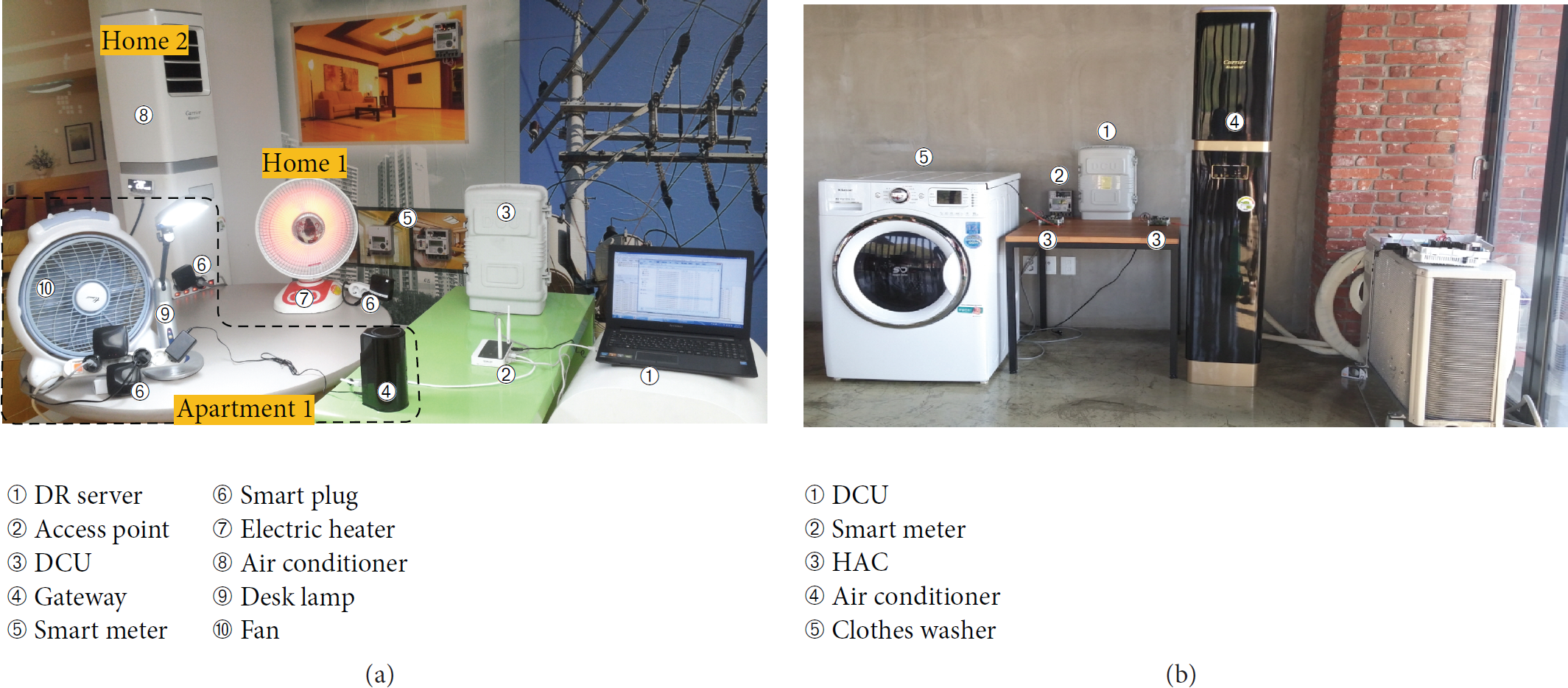
Actual demonstration test environments: (a) ADR demo using the smart plug and (b) ADR demo using the HAC.
Figure 11 illustrates daily load reduction of the home appliance during the DR period. The energy saving rate varies, depending on the DR duration. Figure 11(a) shows a DR service by the smart plug, and all devices are in off state during the defined DR period. Each device executes DR operation at hourly intervals. Four home appliances reduced total power consumption up to approximately 6.882 kWh. Air conditioner and electric heater save majority of power consumption. This figure will increase if the DR interval is extended or more home appliances are involved in the DR event. Figure 11(b) shows the DR service using the HAC. In this service, home appliances respond to smart DR actions by DR level 3, and thus their power is not completely switched off during the period. Their load variations depend on the reconfiguration as described in Table 2. In DR level 3, the air conditioner changes its own operation mode to blast mode, and thus load is rapidly reduced below 50%. The clothes washer delays its own current operations for an hour. As shown in Figure 11(b), power consumption of air conditioner reduced from 1.4 kW to 80 W, and power consumption of clothes washer decreased from 2.5 kW to 0.5 W during a given period. The effect of total power consumption gained was approximately 3 kWh compared with the usual. From the above demo tests, we realized full ADR services based on OpenADR 2.0a protocol through AMI network and verified load reductions of home appliances.

Load variations of home appliances during DR periods: (a) load variations using the smart plug and (b) load variations using the HAC.
5.3. International Standard Certification
OpenADR 2.0 profile is a message exchange protocol for an application layer and provides official certification programs based on a certification test specification document [31]. The certification test consists of an application layer test, a transport layer test, and a security test. In this work, the implemented software programs satisfied all test items including the performance test, protocol implementation conformance statement (PICS), and test harness process. We have obtained an international certification from the OpenADR Alliance, and the test agency is Intertek [32]. Figure 12 shows the official certificate.

OpenADR 2.0 certificate.
From this certificate, we can ensure that the designed residential ADR system performs standard-based DR transaction and enables interaction with some other devices which are based on the OpenADR technology.
6. Conclusion
This paper designed a residential ADR system based on PLC-based AMI network and OpenADR 2.0 protocol. Considering unified standard communication architecture, our ADR model explains how ADR system is configured in residential sectors ensuring interoperability. Various ADR system devices are designed and developed, and AMI devices are modified to deal with ADR transactions. We adopted OpenADR 2.0 protocol for the developed devices for interoperability between heterogeneous systems. The PC-based DRMS and the DRC for the smart meter obtained an international standard certificate, and they are expected to serve as guidance devices in ADR systems. The proposed ADR system enables the construction of an integrated ADR system to be more scalable, stable, and interoperable. We realized full automation of DR services and performed field tests with various home appliances to verify the performance and feasibility. Our system helps utilities to directly control residential load devices when power reserves are lacking. We expect that this study will contribute to realizing residential ADR service in other countries which use AMI system.
Footnotes
Conflict of Interests
The authors declare that there is no conflict of interests regarding the publication of this paper.
Acknowledgment
This research was supported by Smart Grid System Development (no. 10041779) of the Korea Evaluation Institute of Industrial Technology (KEIT) grant funded by the Korea Government Ministry of Trade, Industry and Energy.