
Abstract
This paper presents the development of a newly designed wireless piezoelectric (PZT) sensor platform for distributed large-scale structure health monitoring, where real-time data acquisition with high sampling rate up to 12.5 Msps (sample per second) and distributed lamb-wave data processing are implemented. In the proposed wireless PZT network, a set of PZT transducers are deployed at the surface of the structure, a lamb-wave is excited, and its propagation characteristics within the structure are inspected to identify damages. The developed wireless node platform features a digital signal processor (DSP) of TMS320F28335 and an improved IEEE 802.15.4 wireless data transducer RF233 with up to 2 Mbps data rate. Each node supports up to 8 PZT transducers, one of which works as the actuator generating the lamb-wave at an arbitrary frequency, while the responding vibrations at other PZT sensors are sensed simultaneously. In addition to hardware, embedded signal processing and distributed data processing algorithm are designed as the intelligent “brain” of the proposed wireless monitoring network to extract features of the PZT signals, so that the data transmitted over the wireless link can be reduced significantly.
1. Introduction
Structural health monitoring (SHM) is a system to monitor the integrity of civil structures (e.g., bridges and aircraft wings) and ensure their performance and safety, which has become an attractive research topic in the disciplinary field of mechanical, civil, and electronic engineering. One of the main targets of SHM is the online damage detection, which not only reduces costs by minimizing maintenance and inspection cycles, but also prevents catastrophic failures at earlier stage. This is particularly useful for developing self-monitoring structures, into which “smart” materials are integrated. As a nondestructive evaluation (NDE) method, the well-known lamb-wave-based damage detection has been widely used in SHM [1, 2], which utilizes the features of piezoelectric (PZT) materials and shows great promises for online SHM.
In lamb-wave-based approach, there has been recent interest in the use of PZT transducers, because of their simplicity, robustness, and potentially low cost. In such a PZT-based SHM system, a set of PZT transducers are deployed at the surface of the structure, and one or more PZT transducers work as exciters to induce lamb-waves into the structures. Since the propagation of lamb-waves are affected by the structure's degradation, defects, and damage (e.g., cracks), the characteristics of the lamb-waves propagating from the exciter to these receiving PZT sensors need to be closely monitored and carefully inspected to identify the occurrence of defects and damages within the structure.
Traditional wired SHM systems require long deployment time and significant cost for cable installation. With the maturity of wireless communication techniques, one of the recent challenges in the structural engineering community is the emerging wireless SHM system, which provides a promising solution for rapid, accurate, and low-cost structural monitoring [3–5]. A large number of researches have been focused on the lamb-wave method for damage localization or impact localization for structural health monitoring [6, 7]. However, the majority of these researches are wired SHM systems requiring intensive cabling work, which make it unsuitable for distributed deployment in large structural health monitoring. Martens et al. [8] investigated a platform for PZT sensor based on TMS320F28335 chip with high-resolution PWM and multichannel ADC with 4 MHz sampling rate. This platform is a wired system and, without wireless module, it is not suitable for forming a large PZT network for wide area monitoring. Some researches [9–13] develop some compressive sensing method on lamb-wave. They verified lamb-wave can be reconstructed well by compressive sensing method. However, the compressive sensing method was not easily embedded into wireless node so that distributed processing for PZT network is not able to be achieved.
On the other hand, conventional design of wireless sensor node is not suitable for active sensing in SHM, where the lamb-waves to be sensed are high-frequency ultrasonic signals and contain frequency components up to a few hundred Hz. As a result, high sampling rate is required and a huge amount of data will be collected during the procedure of lamb-wave interrogation. Depending on the structure's material and shape, the frequency of lamb-wave may range from 10 kHz to 1 MHz [1, 2, 8–10, 14–16] and the speed of lamb-wave is usually in the range 5000 m/s (S0 mode). The speed of A0 mode is lowered to 3000 m/s. In order to achieve a resolution of 0.1–2.5 mm in TOF-based damage localization, the sampling rate will be from 2 MHz to 10 MHz. In literatures, various sampling frequencies are used depending on the lamb-wave frequency, wave speed, and resolution requirement of damage detection, for example, 1 MHz in [9, 10], 1.8 MHz in [6], 4 MHz in [8], and 10 MHz in [7, 17]. In our proposed system, we fully made use of the build-in ADC with up to 12.5 MHz sampling rate to provide flexibility to various applications and requirements. The sampling frequency is adjustable by configuring the sampling clock and/or the number of PZT channels.
In addition, due to the complexity of lamb-wave propagation, the damage detection algorithms in SHM usually are computation intensive and require considerable data processing capabilities. However, the existing wireless communication protocol (i.e., IEEE 802.15.4) and wireless hardware motes (e.g., Mica2, MicaZ, and TelosB) in wireless sensor networks are designed for low data rate and low computation applications, which make it is impossible to transmit all the lamb-wave data to a central server that carries out centralized data processing and structure damage identification. To achieve a practical wireless PZT sensor and actuator network for structure health monitoring, the wireless senor nodes must be armed with some kind of distributed data processing and compressive sensing or downsampling algorithm capabilities, such that the amount of data to be transmitted over the wireless link can be reduced.
In literatures, some PZT sensor and actuator nodes have been proposed for structural health monitoring. A wireless sensor node is proposed in [14, 17], where field programmable gate array (FPGA) was used for PZT active diagnosis. However, these wireless sensor nodes have very limited on-board data processing capability for acquired signal. The data transmission is the real-time. Furthermore, the authors in [15, 16] design the wireless PZT sensor and actuator node based on TMS320C2811, TMS320C6713, and TMS320F2812, respectively. However, there are no distributed data processing and distributed wireless network based on nodes investigated in these researches. Dong et al. [18] discussed a Martlet node with TMS320F28069 chip which can support 3 MHz sampling rate for MEMS accelerometer. Conventional wireless sensor node without high-performance core chip is not able to execute the complicated data processing algorithm.
Furthermore, lamb-wave based damage localization is based on the time-space principle that propagation distance (in the space domain) is proportional to the propagation delays (in the time domain) of lamb-waves. To achieve a high accuracy of localization and high resolution of damage image, a precise time synchronization is critical to ensure that the data acquisition and propagation delay calculation are precisely synchronized.
To address the challenges of big data in lamb-wave interrogation, the bottleneck of limited wireless communication bandwidth, and precise time synchronization, a wireless PZT sensor and actuator platform is proposed and developed. The newly designed wireless node features a TMS320F28335 digital signal processor (DSP) and an improved IEEE 802.15.4 wireless data transducer with up to 2 Mbps data rate. Each node supports up to 8 PZT transducers, one of which works as the actuator that generates lamb-wave actuation signal at an arbitrary frequency to drive the external PZT sensor while the responding vibrations at other PZT sensors are sensed simultaneously. In addition to hardware, embedded signal processing and distributed data processing algorithm are also designed as the intelligent “brain” of the proposed wireless monitoring. As a result, the amount of data to be transmitted over the wireless link is reduced significantly. These features enable the developed PZT sensor-actuator node to be deployed easily and suitable for wide area SHM.
This paper is organized as follows. Section 2 presents the network architecture and function diagram of the proposed wireless PZT sensor and actuator network in SHM, followed by the sensor and actuator hardware development in Section 3. The software development is presented in Section 4. Some results are discussed in Section 5 for the purpose of demonstration. And Section 6 is the summary of conclusions and future work.
2. Network Architecture
Similar to the most PZT-based SHM systems, the architecture and function diagram of the wireless PZT sensor and actuator network is as illustrated in Figure 1.

The architecture and function diagram of the wireless PZT sensor and actuator network.
The proposed WSN consists of the following types of components.
(1) PZT Transducer. The PZT transducer either converts mechanical to electric signals, or vice versa. The PZT transducers have two work modes: they can work as either a PZT actuator to excite an elastic lamb-wave according to the electrical signal applied on the PZT crystal, or a PZT sensor to transform the responding elastic lamb-waves into an electrical signal.
(2) Wireless PZT Node. Each node is able to connect to two PZT transducers at least. The node generates excitation signal for driving PZT transducer and acquires data from PZT transducers. PZT sensor and actuator node have embedded distributed lamb-wave data processing for information extraction and downsampling algorithm for reducing data amount of wireless transmission. All wireless PZT nodes form a network and send lamb-wave signal to the base station according to TDMA or CSMA protocol. And wireless PZT nodes in one structure plate should comply with time synchronization for ensuring the damage localization accuracy.
(3) Base Station. This is the sink node which can support big data transmission access, multipoint operations, and time synchronization mechanism for all PZT sensor and actuator nodes. Moreover, this node can implement signal reconstruction for lamb-wave and damage localization.
Groups of PZT sensor nodes are arranged into several structure plates and densely deployed around specific areas of interest and report PZT lamb parameters to the monitoring and human-computer interaction (HCI) system at a remote station. Depending on the application requirements and the size of the area to be monitored, the topology of the network can be a single cluster or multiclusters. Although these PZT transducers are connected to the nearby wireless PZT nodes in their regions via a set of short wires, the featured difference of the proposed system is that the longer distance lamb-wave analog signal cables in wired SHM are replaced by the digital wireless data links between PZT nodes and the remote monitoring system. Therefore, the massive signal cables and costly cable installation are avoided, which is the key benefit of the proposed wireless PZT sensor and actuator network.
While setting up the wireless communication network, time synchronization is also carried out to ensure that all wireless PZT nodes are well synchronized and a common sense of time has been achieved. Once the network is set up and wireless PZT nodes are synchronized, the base station first initializes the lamb-wave interrogation by specifying one or more PZT transducers as the actuators (with appropriate configurations, such as lamb-wave central frequency and amplitudes, according to the requirements from the remote monitoring and HCI center). The base station starts the lamb-wave interrogation procedure by broadcasting a start command to include the start time to all wireless PZT nodes. After sending start command, the base station waits for receiving data from all wireless PZT nodes. Upon receiving the SC from base station, all wireless PZT nodes switch from listening state to a preworking state. Once RF configuration is finished, all wireless PZT nodes start digital-to-analog converter (DAC) function for generating PWM wave excitation. Then, all wireless PZT nodes input PWM excitation signal to PZT transducers and then configure function of analog-to-digital converter (ADC) and direct memory access (DMA). Once sensing event is detected, wireless PZT nodes start to execute data acquisition of lamb-wave signal. The DMA controller controls lamb-wave data to be sent from ADC register to data queue. The DSP controller in wireless PZT node acquires PZT transducer's data from data queue and executes data processing. Finally, all wireless PZT nodes transfer processed data to the base station in the light of TDMA or CSMA protocol.
3. Hardware Architecture
3.1. Hardware Schematic
The block diagram of the proposed wireless PZT node is shown in Figure 2. The wireless PZT node consists of three components, namely, conditioning board, DSP base board, and radio board.

The hardware schematic representation of sensing wireless PZT node.
The conditioning board is an analog signal processing board that has two tasks: (1) lamb-wave execution: this is to amplify the 3.3 V lamb-waveforms generated by the DSP to an appropriate level, so that a required lamb-wave can be induced at the PZT transducer (actuator mode); (2) lamb-wave detection: this is to amplify and filter the weak and noisy lamb-wave signal detected by the PZT transducer (sensor mode) to 3.3 V level for analog-to-digital conversion at the DSP. The excitation designed is on the basis of our previous work at our lab [2] and the excitation circuit for wireless active sensing node is presented in [16]. The lamb-wave detection circuit consists of a group of AD8608 operational amplifiers (Op AMPs) configured in charge amplification mode. Unlike the voltage preamplifiers that suffer from distance/attenuation effects, charge amplifier is selected to maintain the signal sensitivity regardless of distance from the passive sensor to the preamplifier. Therefore, it is suitable for the long lengths of sensor input cable. The AD8608 is chosen because of its low bias current (1 pA maximum), low noise (12 nV/maximum), and low offset voltage (65 μV maximum). The output of the U2A OPAMP is 0.1 V to 3.2 V which matches the input range of the ADC (0 V to 3.2 V) with 100 mV headroom to maintain linearity (Figure 3).
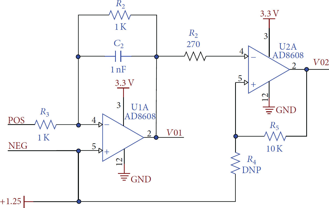
The schematic diagram of lamb-wave detection circuit.
The switching circuit is presented in [1] at our lab. In active sensing, the PZT transducer may switch between two operation modes: excitation mode and receiving mode. A switching circuit is needed to connect the excitation circuits and detection circuits to different PZT transducers. The switching module consists of two sets of low crosstalk single pole double throw (SPDT) relays that are controlled DSP. At a given time, only one PZT is connected to the excitation amplifier as the lamb-wave generator; other PZT transducers are connected to charge amplifiers as the signal detector. The connections change in round-robin scheduling.
In base board, one distinct feature of the microcontroller TMS320F28335 is the capability of high-speed data acquisition. The direct memory access (DMA) module on TMS320F28335 allows the wireless PZT node to collect sensor data at 10 MHz sampling rate up to by 12-bit ADC with 6.25 Msps. The core of the base board is distributed data processing unit which is able to execute wavelet or Hilbert transform, time delay calculation for lamb-wave, and downsampling algorithms. The radio board contains ATSAMR21G18 microcontroller, DSP module interface, and RF module.
3.2. Base Board
A typical smart wireless sensor node has limited memory and limited computational ability and battery power. These conditions should be taken into account when the downsampling algorithm is embedded into wireless sensor board. The base board should be chosen according to the following aspects: (1) it should have SPI or I2C interface for communication with RF board; (2) it should support high data transmission rate for large amount of lamb-wave or other complex signals; (3) it should support high enough crystal frequency for working; (4) it should support certain memory storage for data cache. For low-cost low-power measurement devices, the programmable DSP could be an efficient digital, programmable, and real-time platform.
The base board, as detailed in Figure 4(a), is a four-layer PCB roughly with the size of 13.5 cm by 7.5 cm. A Texas Instrument microcontroller TMS320F28335 (real-time digital signal processor with controller features of Delfino-family) in base board, running up to 150 MHz clock frequency, is adopted in the wireless sensing node to execute high sampling data acquisition and on-board data processing. Additional important features of this DSP are on-board DMA controller, 16-bit enhanced pulse-width modulators PWM (HR-EPWM), 12-bit multichannel sampling/hold circuit, internal flash memory of the program, floating point hardware arithmetic, and so forth. The PWM works at clock frequency of 100 MHz and can be used as precise digital-to-analog converters (DAC) or trigger the analog-to-digital conversion (ADC). The DSP chip also includes 12-bit resolution multiplexed ADC with a conversion rate of up to 10 MHz or more and has 8 simultaneous sample-and-holds. So, this chip has high-performance digital-to-analog and analog-to-digital conversion without extra components. In this board, the P8 I/O interface and P9 analog interface connector are used for communicating with RF board and acquiring sensor data, respectively. The ADCL0 pin should be connected to GND pin to make sure that the ADC module in DSP adopts internal reference voltage.
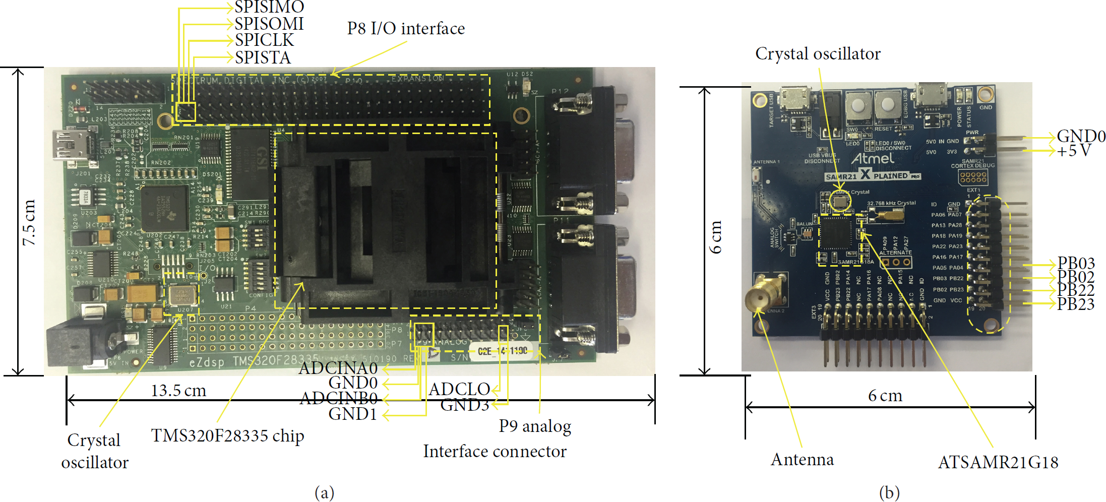
Prototype of the proposed wireless PZT actuator/sensor node, which consisted of two parts: (a) DSP base board; (b) IEEE 802.15.4 radio board.
3.3. Radio Board
The radio board, as detailed in Figure 4(b), is employed in this research. The Atmel SMART SAM R21 board with low-power microcontroller ATSAMR21G18 is chosen. It adopts a 32-bit ARM Cortex-M0+ Processor and an integrated ultra-low-power RF233 as 2.4 GHz ISM band transceiver with a maximum data rate of 2 Mbps. This device is available in 48-pin packages with up to 256 kb Flash, 32 kb of SRAM, and is operating at a maximum frequency of 48 MHz.
Sensor data is sent from base board using SPI bus (PB03, PB22, PB02, and PB23) to the radio board, respectively. The radio board is a two-layer PCB and the size of the board is 6 cm × 6 cm roughly, as shown in Figure 4(b). The two vertical header pins are shown on both the right side and bottom side. The 4-pin horizontal headers interface with vertical headers (SPICLK, SPISIMO, SPISOMI, and SPISTA) on the base board to enable external data to access from base board. In transmitting state, the radio board consumes 35.5 mW of power (26 mA of power at 1.8 V) but less than 2 μW of power (1.1 μW of power at 1.8 V) in power down mode.
Another task of the radio module is time synchronization. It is well known that time synchronization plays a key role in all Time-of-Flight- (TOF-) based structural health monitoring systems. The accuracy of arrival time calculation and the resolution of damage localization are degraded by the errors in time synchronization. Recognizing the importance of time synchronization, we take dual-processor architecture in our hardware system, in which a second processor (i.e., the ATSANR21G18 at radio module) is separated from the computation-intensive data processing and reserved for only wireless communication and time synchronization. Therefore the time accuracy of interrupt-based time synchronization and time-stamping is not compromised by other tasks (e.g., ADC interrupts, delays for intensive data processing). At a lower computation burden, the interrupt response is faster and lower jitters and delays can be guaranteed. Thus a better time synchronization accuracy can be achieved. In this paper, a simple time synchronization scheme is presented, which is suitable for a single-hop network only. In his scheme (as illustrated in Figure 5), the PZT sensor nodes start with an idle state (no sampling nor data processing) after initialization and keep waiting for the “START” command from the base station. Once it receives the “START” command, all the nodes start sampling immediately. However, it is not fit for the multihop network, where we need some advanced techniques (such as packet-exchange time synchronization in our previous work) to keep the node's clock synchronized all the time. The proposed dual-processor architecture has the capability for precise time synchronization by packet-exchange (e.g., the IEEE 1588 PTP-like time synchronization) and our future work is to implement our previous time synchronization work [19, 20] into this hardware platform.

Functional blocks of the wireless PZT network.
4. Software Architecture of System
4.1. Operation Overview of PZT Sensor Network Operation
Figure 5 illustrates a procedure within a three-stage wireless sensor network for autonomous damage or defect detection. The entire wireless sensor network may consist of PZT node and base station connected to PC. Several PZT nodes and a base station form a group to cover a geometrical area. The diagnosis command is initiated from the PC through base station. After informing all wireless PZT nodes, the base station broadcasts an initial command to wireless PZT node and triggers the signal excitation of sensor nodes. Each wireless PZT node immediately starts data acquisition after receiving the initial command and records the measurements. The measurements are subtracted from the prestored sensor data for healthy structure to obtain the scattered wave signal form the damage.
Conventional wireless sensor nodes normally utilize centralized architecture. In this architecture, analog-to-digital converters (ADC) and memory chips are directly connected to I/O ports of microcontroller. The microcontroller must access the peripheral chips sequentially and clock multiple clock cycles that are required to complete an operation which involves several peripheral chips. Most peripheral chips should be active while waiting for trigger signal from microcontroller. For such architecture using conventional design, high sampling rate is almost impossible.
4.2. Wireless Command and Data Communication
The network header, MAC header, and application payload are encapsulated inside the standard IEEE 802.15.4 data frame payload, as shown in Figure 6.

The format of wireless packet.
The general format is composed of a IEEE 802.15.4 MAC header, network header, application payload, optional message integrity code (MIC), and a check sum (CRC). When the RF board gets the acquired data from base board by SPI interface, the acquired data will be filled into the payload format. Once the payload has been filled to the full, wireless packet will be sent to the base station. The maximum payload is 112 bytes. The 2-byte timestamp format in network header stores the timestamp of wireless PZT nodes or base station, as shown in Figure 6.
4.3. Data Acquisition and Processing
In Figure 7(a), the flowchart demonstrates typical data sampling cycle of conventional design, such as prototype of wireless nodes, TelosB motes, Imote2, and Mica motes. These conventional motes have an internal 12-bit ADC in microcontroller. The microcontroller sends clock signal and control signals to the ADC to trigger sampling cycle conversion. The internal buffer is set up to get data from the ADC. The reading takes 12 periodic operations and an ADC clock signal is generated in each period for filling the buffer bit by bit. After the data has been read out entirely, the microcontroller provides a clock signal and control signals to the on-board flash. Before writing the data into the flash bit by bit, the microcontroller takes some instructions to send address to the flash. The flash saving operation also takes 12 periodic operations, each of which involves several instructions and a few clock cycles. Then, the sampling cycle ends and another sampling cycle may start again. This architecture clearly reveals the inefficiency of wireless sensor node designed with an ordinary microcontroller.

Data sampling and collection process comparison between (a) the conventional wireless sensor node with low sampling rate (usually up to a few kHz) and (b) the proposed wireless PZT sensor/actuator node with burst sampling rate up to 12.5 MHz.
Figure 7(b) presents an improved sampling design using TMS320F28335 chip. The chip internally has some controllers, including first-in-first-out (FIFO) DMA controller for sampling data input and output, SRAM controller, and a clock generator. The DMA algorithm has been widely used to allow hardware to access memory independently. To enable a wireless sensor node for high-speed applications, some algorithms such as semi-DMA approach are applied to extend the traditional architecture of wireless sensor node. In our design, with the DMA controller, the main microcontroller TMS320F28335 chip can be released from the task of data transfer. The sampling data transfer and data acquisition can be more efficient when DMA is adopted. The 12-bit sampling data is acquired by the ADC and saved into the internal DMA buffer in FIFO input mode by DMA controller. Meantime, the DMA controller and address controller control the data to access the SRAM in FIFO output mode. The sampling data is moved from the internal DMA buffer to SRAM at 16-bit length which is the I/O width of SRAM. Each clock cycle have 8 continuous sampling operations and one writing operation for writing data for SRAM. As a result, sampling data are encapsulated according to bit alignment in internal DMA buffer and the DMA, ADC, and the SRAM can be fully utilized without compromise.
The process diagram illustrates the main stages of data processing for lamb-wave signal, as shown in Figure 8. The process begins with the data record of lamb-wave signal after excitation. The first two stages are operated in wireless PZT node. At first stage, data about the response signal with S0, A0, and other modes are collected. Then, the acquired raw data is sent to base station if nondownsampling method is adopted or is downsampled first and then is sent to base station. This stage including downsampling method aims at reducing amounts of lamb-wave signal's transmission for saving energy consumption and raising the efficiency of data transmission. The third stage in the process is operated in base station. At base station, the envelope is reconstructed from the raw data or downsampled data, and then TOF estimation is calculated by propagation delay. Finally, The TOF estimation is used for damage localization.
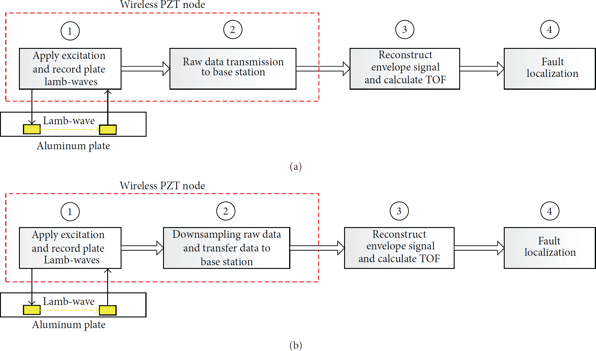
Data processing for lamb-wave signal with (a) nondownsampling algorithm (b) and downsampling algorithm.
5. Proof-of-Concept Tests and Performance Evaluation
In order to evaluate the performance of the developed wireless PZT sensor nodes, a series of proof-of-concept lab tests have been carried out and the results are presented in this section. Two key performance indices of the proposed wireless PZT sensor and actuator network are (1) distributed signal processing for envelope detection and propagation delay estimation; (2) downsampling algorithm for reducing the amount of data to match the wireless communication bandwidth, while retaining the structure health information as much as possible.
The lab test platform is shown in Figure 9. As a proof-of-concept lab test, the platform consists of a computer working as a graphic user interface to the end-user, a wireless base station that connects to the PC with the wireless network, and the designed wireless sensor node (highlighted by a red square). As our focus is to verify the distributed signal processing and wireless transmission, the conditioning board is replaced by a power amplifier and a charge amplifier in this lab test. Two PZT sensors are attached to the surface of an aluminum plate bar. Left one is the actuator connected to a power amplifier that amplify the five-cycle sinusoidal tone burst signal to generate a lamb-wave. The PZT at right end of the aluminum bar is the PZT sensor to receive the propagated lamb-waves. The lamb-wave signal detected by the PZT sensor is first conditioned by a charge amplifier to the range of 0–3.3 volts. Then the amplified signal connects to the DSP board and RF board for digital-to-analog conversion, local signal processing, and wireless transmission. Once the base station receives the transmitted data, it simply forwards the data to the PC via a USB cable.

Lab test platform for the wireless PZT sensor network.
In our lab tests, the waveforms generated from a lamb-wave propagation simulator are used for performance evaluation [21]. These waveforms are injected into the signal generator to mimic the PZT transducer. The output signals from the signal generator are connected to the DSP baseboard that processes the signal locally and sends the extracted feature to base station through the wireless link. Two different envelopes are detected by using Hilbert transform and wavelet transform, as shown in Figures 10 and 11, respectively.

Lamb-wave detection. (a) Excitation signal

Lamb-wave detection. (a) Excitation signal
The signals used in this proof-of-concept test are for a pair of PZT actuator and sensor on an aluminum plate of 2 mm thickness, where the PZT sensors are separated from the PZT actuator at 100 mm distance. Figures 10(a) and 11(a) depict the hamming-windowed 5-peak tone burst excitation signal (blue line) of carrier frequency 100 kHz and its hamming window (red line). The excitation signal has 5 cycles of the sinusoidal signal and last for 25 μs. For the purpose of evaluation, the excitation frequency was tuned to 100 kHz for a good separation of the fundamental symmetric mode S0 wave and the fundamental antisymmetric mode A0 wave.
At the PZT sensor node, the reception lamb-wave after 100 mm propagation was sampled for 400 μs by the build-in ADC of 28335 DSP at a sampling rate of 12.5 Msps with the resolution of 12 bits. The sampled data is of 10 k bytes (5 k words) and stored in the DSP RAM. Figures 10(b) and 11(b) show the sampled data (the blue line labeled with raw signal) and the clear separation of the S0 and A0 mode. The dispersion of the A0 mode for such a wave at 100 kHz frequency after 100 mm propagation can also be clearly seen.
5.1. Basic TOF Extraction by Hilbert Transform
The fundamental principle of lamb-wave structure health monitoring is the fault localization by time-of-flight of the received waves. With the given wave propagation speed, once the TOF τ is found; the location of the reflector damage can be determined according to


The cross-correlation coefficients are further processed by the Hilbert transform to derive its envelope for TOF estimation. The calculated cross-correlation function
5.2. TOF Extraction with Shannon Wavelet Transform
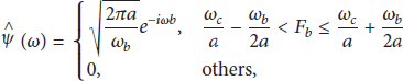
Wavelet transformation method is able to analyze low and high frequencies at the same time, even respecting the uncertainty principle [22]. Therefore, it is chosen as a method to analyze lamb-wave. The Continuous Wavelet Transform (CWT) is a linear transform that correlates the harmonic waveform


From the envelope of the cross-correlation function, the first peak of
5.3. Downsampling and Data Recovery
In order to improve the accuracy of the fault location estimation carried out at the base station, single TOF may not be informative enough for the data fusion algorithm. The envelopes are also needed in most data fusion processes. However, given the sampling rate of 12.5 MHz, 12-bit resolution, and monitoring duration of 400 μs, the amount of collected data is about 10 k Bytes for just one single PZT sensor channel. The data has to be segmented into 92 packets due to the 112 Bytes' limits of wireless packet size and it will take about 1 second under ideal conditions (collision-free) to complete the data transmission at 125 kbps IEEE 802.15.4 standard data rate. When the number of wireless nodes increases and the number of PZT sensor channels per node increases, the time for wireless data transmission will increase dramatically. Further concern will be the power consumption demanded for such huge data transmission.
Therefore, the amount of data to be transmitted wirelessly has to be reduced to a great extent to enable practical wireless data transmission. A downsampling algorithm is demonstrated here to prove the concept.
The downsampling ratio is one of the indicators to measure the degree of data downsampling whose definition is the downsampling ratio between the original signal data quantity and downsampled data amount written as the follows:

The envelope detected in previous stage is further processed by a downsampling process to reduce the amount of data to be transmitted over the wireless link. At data sink, the envelope is reconstructed from the downsampled data. The results are shown in Figure 12, where the downsampled envelope (blue circle) fits the original envelope (red line) very well.

Downsampled and reconstructed envelope signal. The downsampling ratio is 1 : 20.
The envelope signal before downsampling consists of 4000 sample points and is of 8 k Bytes. At the downsampling ratio of 20 and by removing the noise data before the arrival of the S0 wave, the number of samples is reduced from 4000 to 156, which makes it possible for WSN to collect the data. As a result, sending an envelope signal to the base station is accomplished by transmitting two packets only, which is a significant saving in terms of communication costs and power consumption.
Another benefit of the proposed downsampling approach is the noise filtering. Due to the use of FIR filter in the downsampling algorithm, the reconstructed signal from the downsampled points is smoother than the original envelope (as shown in the zoomed-in insect in Figure 13). It can be seen that the S0 peak value in downsampled envelope signal after zooming in Figures 13(a) and 13(b) is 107.26 μs and 107.54 μs, respectively. The two values are almost the same, which proves the downsampling sensing is feasible in wireless PZT network using two signal methods. As a result, it will contribute to the improvement of signal-noise-ration and the accuracy of fault localization.

Downsampled envelope signal.
5.4. Performance Analysis and Discussion
The reconstructed envelope signal is reconstructed from the downsampling data by interpolating values into downsampling data in cubic interpolation algorithm. For instance, as the point number of downsampling data is reducing to 200 from 4000 points in original envelope signal, 3800 points can be interpolated into downsampling data by interp1 function to reconstruct the envelope signal. The time instant of peak value in interpolating fitting envelope signal and original envelope signal are calculated by max function in MATLAB tool.
Reconstruction Error Evaluation. Reconstruction error is on behalf of the similarity degree of the reconstructed signal and the original one. In general, the formula is

As shown in Figure 14, the absolute error of the reconstructed signal with the original signal is within

Absolute reconstruction error under Shannon wavelet transform ((a) and (b)) and Hilbert transform ((c) and (d)).
Time Delay Error Estimation. In the application of damage detection, one objective of signal processing is to estimate the delays in time-of-flight of S0 signal. Therefore, time delay errors of downsampling are evaluated and compared here. In this paper, the time delay error is defined as the difference between the time instant of peak value in reconstructed envelope of S0 signal and the time instant of peak value in original envelope of S0 signal, as shown in Figure 15. In this paper, time delay error is adopted to evaluate the performance of signal processing algorithm. The percentage of time delay error is defined as

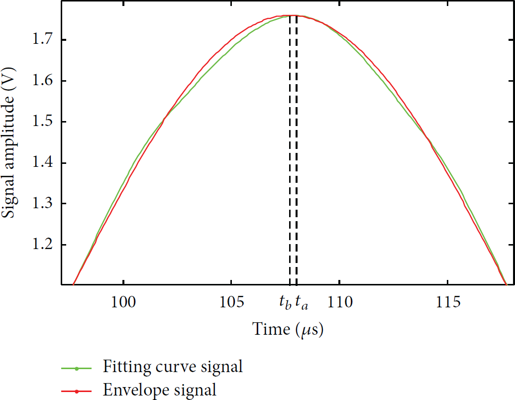
S0 time delay error in S0 mode between reconstructed signal and envelope original signal.
As shown in Table 1, the higher the downsampling compression rate is, the higher the time delay error is, which is as we expected. The Shannon wavelet transform and Hilbert transform have similar performance at the lab tests. At higher compression ratio, Shannon wavelet transform is slightly better than Hilbert transform. We believe this is due to the fact that our lamb-wave signals at the lab tests are clean. In practice, when the signal-noise-ratio is poorer, it is expected that Shannon will be better than Hilbert. This verification will be our future work. The resolution of damage localization in wireless PZT network will benefit from lower time delay errors.
Time delay error in different downsampling ratio and transform methods.

6. Conclusions and Future Works
This paper presents next-generation, low-cost, wireless PZT node and network for structural health monitoring. The node provides a powerful wireless platform which is able to perform high-frequency precise data acquisition and distributed local data processing. A series of proof-of-concept tests have been done and the results of both the envelope detection and downsampling algorithms are presented, from which the performance of the proposed wireless PZT sensor network is verified. For the future work, more advanced distributed data processing algorithm (such as wavelet denoising) will be deployed for practical experiments. The comparison of the performance between the proposed wireless network and wired network will be also investigated to evaluate whether the proposed wireless system match the wired system. Another issue to be addressed in such a distributed wireless PZT sensor network for structure health monitoring is the time synchronization among these wireless nodes.
Footnotes
Competing Interests
The authors declare that there is no conflict of interests regarding the publications of this paper.
Acknowledgments
This work is supported by European Commission project Health Monitoring of Offshore Wind Farms (HEMOW) under Grant FP7-PEOPLE-2010-IRSES-GA-269202 and EPSRC project Novel Sensing Network for Intelligent Monitoring (NEWTON) under Grant EP/J012343/1.