
Abstract
The network-based mobility management is adapted to the OpenFlow architecture for mobility service at Software Defined Networking (SDN), and data structure for mobility service is proposed. SDN is a newly proposed Internet architecture which decouples the data and control planes, and mobility management is one of the most important issues in SDN. In order to provide mobility management service by utilizing the mobility scheme proposed earlier in a new network environment, the existing mobility schemes need to be modified. Particularly, the characters of the network environment need to be considered when designing the function of the network entities and data structure. Our proposed mobility management scheme is focused on the centralized control mechanism of SDN. We referred to Proxy Mobile IPv6 (PMIPv6) and OpenFlow-based PMIPv6 with a centralized mobility management controller (OPMIPv6-C). It has a merged data structure for the mobility service on SDN controller and minimizes the number of switches which need flow table modification at handover. At the performance analysis chapter, we compare the signaling cost at the registration and handover phase, packet delivery cost, and handover latency between the proposed scheme and OPMIPv6-C.
1. Introduction
Software Defined Networking (SDN) is newly proposed network architecture for the programable network [1]. SDN separates the control plane and the data plane by the role of the network functions. The data plane is responsible for the packet forwarding and the control plane performs other functions. The control functions which were located on the distributed devices are gathered to the centralized controller. Due to the separation, standard interface is needed for the interaction between the control plane and data plane. The OpenFlow is one of the standard interfaces between the control and data plane, and it is proposed by the Open Networking Foundation (ONF).
The OpenFlow architecture consists of the OpenFlow-enabled switch, secure channel, and OpenFlow protocol. The OpenFlow-enabled switch is the switch which satisfies the OpenFlow specification. The secure channel is the path for transmission of the OpenFlow messages between the controller and switches. The OpenFlow protocol is the format of OpenFlow messages for the control, notification, and packet transfer.
The mobility management scheme is able to be categorized into two types: the network-based and host-based mobility management or micro and macro mobility management protocol. The difference of the network-based and host-based mobility management is the subject of the mobility-related signaling. The network entities are the subject of mobility-related signaling in the network-based mobility management. The MN is subject of the mobility management signaling in the host-based management scheme. The difference of the micro and macro mobility management is the mobility management area for handover control. The macro mobility management protocol handles the interdomain mobility and micro mobility management protocol controls the intradomain mobility, respectively. PMIPv6 is one of the network-based micro mobility management protocols and it is standardized by IETF. The network entities, LMA and MAG, are responsible for the mobility control signaling instead of the MN, and PMIPv6 performs the intradomain mobility management service.
Several mobility management schemes for mobility service in SDN have been suggested [2–5]. Reference [2] suggests a brief idea for mobility service in SDN, but it does not describe any detailed mobility management procedures or data structure. References [4, 5] apply PMIPv6 to SDN. They focused on the adaptation of Proxy Mobile IPv6 (PMIPv6) to OpenFlow architecture over SDN. They keep PMIPv6 architecture and relocate the mobility control functions into SDN controller. Reference [4] proposes locating the distributed network entities, local mobility anchor (LMA), and the Mobile Access Gateway (MAG), into SDN controller. Reference [5] is similar to [4]. However they still use PMIPv6 signaling and distributed data structure. Reference [3] suggests PMIPv6-based mobility management scheme on SDN. It gathers the mobility management function into SDN controller and uses the packet rewriting mechanism instead of the tunneling mechanism. However, due to the packet rewriting mechanism, the access switch cannot handle more than one MN.
In this paper, we proposed the OpenFlow-Based Mobility Management (OMM) scheme and an integrated data structure for mobility service in SDN. The proposed scheme integrates the mobility management functions into a single mobility management entity (MME) and organizes the new data structure which is based on the LMA and MAG data structure. It eliminates all entries related to mobility management control messages and data tunnels and integrates the duplicated entries in MAG and LMA. OMM has the Flow Matrix which records the flow paths for mobile node (MN). And it adapts the path flow setup mechanism of [5, 6].
The rest of this paper is organized as follows. Section 2 summarizes the related works. In Section 3, the architecture of the proposed scheme is introduced in terms of the data structure and mobility management entity. In Section 4, the signaling flow of the proposed scheme is introduced in terms of the registration phase and handover phase. A performance evaluation is performed in Section 5. Finally, Section 6 concludes this paper.
2. Related Works
Mobility Support in Software Defined Networking [2] suggests the basic structure for the mobility management in SDN. But it proposes only the idea and does not suggest any specific method.
Mobility Management Framework in Software Defined Networks [4] and an adaptation of Proxy Mobile IPv6 to OpenFlow architecture over Software Defined Networking [5] suggest adaptation of PMIPv6 into SDN.
Reference [4] is focused on location of the mobility management entities for mobility service in SDN. It moves the LMA and MAGs to SDN controller as the applications and all mobility management follows PMIPv6. It keeps LMA and MAG functions and uses tunneling to forward data packets. Reference [5] suggests two mobility management schemes: OpenFlow-based PMIPv6 (OPMIPv6) and OPMIPv6 with a centralized mobility management controller (OPMIPv6-C). OPMIPv6 has LMA control function on SDN controller and MAGs are located at the access switches. OPMIPV6-C suggests centralized MAG at SDN controller as well as the LMA control function, but the two modules are not unified. Both schemes use the same mobility control mechanism in PMIPv6, but these two schemes eliminate packet tunneling. They use two flow entries on the OpenFlow-enabled switches on the path between the access switch and the gateway switch. One entry handles the downstream traffic and the other upstream traffic. There is no packet modification at the access and gateway switches.
A solution for IP Mobility Support in Software Defined Networks [3] also proposes the centralized mobility management function at the SDN controller. The scheme does not use tunneling to forward data packets from a CN to the MN direction. The GW of the SDN domain rewrites the destination address of packet to IP address of the AS, and the AS reverts its IP address to the original destination address when it receives the forwarded packet. Due to the rewriting policy, the AS cannot handle more than one MN. The AS cannot identify which destination address should be used to replace the destination address of the incoming packet as the incoming packet does not have any such indicator in the packet. In addition, the scheme uses the triangular packet forwarding but the ingress filtering problem is not considered at all.
3. An OpenFlow-Based Mobility Management
The OpenFlow-Based Mobility Management (OMM) refers to PMIPv6 to identify the requirements of the mobility management. In this paper, we assumed two things. First, the MN attachment is notified by layer-2 notification which contains the MN's identifier. Second, the IPv6 address of MN is created by using the home network prefix (HNP). These are the same assumptions in PMIPv6.
3.1. Architecture
The proposed scheme consists of an MME on the centralized SDN controller, OpenFlow-enabled switches, and an Authentication, Authorization, and Accounting (AAA) server. SDN controller is the basement of control applications and it supports them using internal functions, such as the topology manager, database, and link discovery [7]. The OpenFlow-enabled switches provide packet forwarding within SDN domain. The AAA server authenticates MNs for the mobility service. If an MN has the right of the mobility service, the AAA provides the MN's profile to the MME. The solid lines and dotted lines in Figure 1 indicate the control flow and the data flow.

System architecture.
3.1.1. OpenFlow-Enabled Switch
An OpenFlow-enabled switch is a switch which satisfies the OpenFlow specification [8]. According to their role in OMM, the switches are categorized into access switches (ASs), intermediate switches (ISs), and gateway switches (GWs). An AS provides the network access service to MNs. A GW connects the access network with the Internet. ISs are located on a flow path between the AS and the GW. A Crossing Switch (CS) is one of the ISs, and it is located at the branch point of old and new flow paths of an MN when a handover occurs. The CS is used to reduce the number of flow table updates on switches affected by the handover.
3.1.2. Mobility Management Entity
An MME is a control application for the mobility management and it runs over SDN controller. The MME detects the attachment of an MN and provides the mobility service for MN. After authentication of MN, it allocates the HNP for the MN and establishes downstream and upstream flow paths for the MN. It also performs the handover procedure when the MN moves into another AS.
3.2. Data Structures in the MME
The MME maintains the attached MN's information at the binding cache. To perform the HNP allocation and flow path establishment, the MME has two additional data structures: a GW-HNP mapping table and a Flow Matrix. These additional data structures are created before the MME provides the mobility service.
3.2.1. Binding Cache
The Binding Cache is a list of Binding Cache Entries (BCEs) for each MN. A BCE is created when a new MN is attached to SDN domain and is updated when the network state or the attachment point of MN is changed. Each BCE contains MN's information and Flow Matrix information. The format and the acquisition process of each field follow these in PMIPv6 specification. The MN information includes an MN's identifier (MN-ID), a link-layer identifier (LL-ID), a list of MN's home network prefixes (MN-HNPs), and an Access Technology Type (ATT), as shown in Figure 2(a). The Flow Matrix information includes the gateway index (

The mobility-related information tables in the mobility management entity.
3.2.2. GW-HNP Mapping Table
When a new MN attaches to SDN domain, the MME must allocate an HNP for the MN. If the MME may obtain the HNP from the MN's profile, the MME must know which GW handles the HNP for the MN. If not, the MME randomly assigns a corresponding GW for the MN and allocates one of HNPs handled by the GW. The MME can know which GW manages the assigned HNP based on the GW-HNP mapping table, as depicted in Figure 2(b).
3.2.3. Flow Matrix
The Flow Matrix has the flow-related information for providing mobility service in SDN domain. It contains three pieces of information: a list of flow paths, the pairs of a previous AS (pAS) and CS, and a list of HNPs, as shown in Figure 2(c). An element in the list of flow paths is described as a pair of an upstream flow path and a downstream flow path, which is a Switch-ID (port index for upstream, port index for downstream). For example,
After the GW is selected, the MME has to find the flow paths between the AS to which the MN is attached and the selected GW. Each MN needs two flow paths: one for upstream traffic and the other for downstream traffic. The two flow paths use the same switches, but their in/out ports are reversed. As the wired network topology is pretty stable, these flow paths can be calculated proactively. SDN topology information for the flow path calculation can be taken from the underlying SDN controller and can be detected dynamically using the Link-Layer Discovery Protocol [9]. Based on the network topology, the MME can calculate the best flow path between each AS and GW. The precalculated flow paths are recorded in the Flow Matrix. Each cell of the Flow Matrix is accessed by using
When an MN is moving into a nAS, the information of the new flow path can be found with the nAS index in the Flow Matrix. Then, the flow table entries of switches on the new flow paths must be updated. However, the switches included in both the old and new flow paths except the CS should be excluded for the flow table entry update. Therefore, each cell of the Flow Matrix includes CS information for all other flow paths. Only flow table entries on switches between the CS and the AS on the new flow paths need to be updated.
A cell in the Flow Matrix also includes a list of HNPs. These HNPs share the flow paths between the AS and the GW. When the flow paths in the cell are changed due to the underlying network topology change, all flow table entries of switches affected by the topology change must be updated. The MME uses the HNP list to update these flow table entries.
Figure 3 shows an example of the Flow Matrix.

An example of the Flow Matrix.
If the MN moves from the
The Flow Matrix provides several advantages. Firstly, it prevents the duplicate computation about flow paths. The MME already maintains the precalculated flow paths in the Flow Matrix. Thus, when a new MN attaches to one of ASs, the MME does not calculate flow paths and just uses the corresponding cell of the Flow Matrix. Secondly, the number of the flow paths managed by the MME can be reduced. A flow path is configured per MN in SDN. However, the flow path can be shared in the proposed scheme if MNs belong to the same cell of Flow Matrix. Thirdly, the MME can easily handle the topology change. Flow table entries affected by the underlying network topology change must be reestablished. The MME can detect the flow paths affected by the topology change by recalculating the Flow Matrix. If any flow paths are updated after recalculation, the MME must update the corresponding flow table entries on switches on the affected flow paths with the HNP list. For each HNP in the HNP list, two flow table entries on each switch on the affected flow paths are modified by the MME.
4. Procedures of OpenFlow-Based Mobility Management
In this section, the registration procedure and intradomain handover procedure are described in detail.
4.1. Before Mobility Service
The MME creates the Flow Matrix and the GW-HNP mapping table. If SDN controller supports the flow path setup, the MME requests the flow path to SDN controller for an MN between each GW and AS. If not, the MME requests the network topology to SDN controller and computes the flow paths between each GW and AS. The MME records it on the Flow Matrix.
4.2. Registration to MME
The registration procedure is shown in Figure 4 and is as follows.

The mobile node registration signaling flow.
4.2.1. Mobile Node Attachment
When an MN is attached to SDN domain, the AS is notified by the L2 notification and forwards it to the MME. The L2 notification contains the MN-ID, LL-ID, and ATT.
4.2.2. Authentication
The MME sends the MN-ID to the AAA server for authority of the mobility service. If the MN has the right of the mobility service, the AAA authorizes and replies the profile of the attached MN. The MN's profile includes the GW information which will be allocated to MN and the HNP assigned to the connected interface. If MN's profile does not include HNP, the MME allocates an HNP for the MN based on the LL-ID and the GW-HNP mapping table.
4.2.3. Select the Flow Path in the Flow Matrix
At this time, the MME recognizes the indexes of the GW (
4.2.4. Send the FMOD and Update the Flow Table in Switches
After selecting the flow path, the MME can know the ISs between the AS and the GW for the MN. The MME sends a Flow Modification (FMOD) message to the switches on the path as soon as possible. Then, the switches update their flow table for the MN's upstream and downstream flows.
4.2.5. Router Advertisement
The MME sends a unicast Routing Advertisement (RA) message to the MN via the AS using POUT. The RA conveys the HNP and the other configuration parameters. The AS forwards the RA to the MN via the port to which the MN is attached. After receiving the RA, the MN configures an IP address.
4.3. Intradomain Handover
The handover procedure is shown in Figure 5 and is as follows.

The signaling call flow for intradomain handover.
4.3.1. Mobile Node Detachment and Attachment
When the MN attaches to a nAS, the L2 notification is sent from nAS to the MME.
4.3.2. Select the New Flow Path in the Flow Matrix
The MME looks up the matching BCE based on the L2 notification. If the BCE is found, a handover is performed. The MME looks up the cell
4.3.3. Send the FMOD to Switches and Update the Flow Table
The MME sends the FMOD to the switches on the flow path between the nAS and CS in order to update the flow table entries. If not, the downstream packets will be forwarded to the previous AS. The switches between CS and nAS update their flow table.
4.3.4. Router Advertisement
The MME sends a unicast RA to the MN via the nAS, like the registration phase.
5. Performance Evaluation
This section describes the topology and the messages which are used by OPMIPv6-C and OMM protocol for evaluation. The topology consists of a single GW and several switches to represent a SDN administrative domain. We developed the analytical cost model to evaluate the performance of OMM and the OPMIPv6-C based on [10]. The following notations are used to develop the cost models [5, 10–13].
5.1. Network Model
We exploited the similar network model and the concept of [5] for evaluations. The topology shown in Figure 6 is used to represent provisioning entities in OMM and OPMIPv6-C. We assumed that the controller is connected by the wired line directly to all switches in the domain. That means that the hop count between the controller and the switches is one. The CN is placed on the outside of a given administrative domain, and the movement of MN is limited within the domain.

The network topology.
The
5.2. Mobility Model
Both OPMIPv6 and OMM are local mobility management protocols. Thus, we only consider intradomain mobility based on that presented in [5, 14]. In order to evaluate the mobility model, we assume that all access points (AP) in the given domain have a circular coverage of the same size S. The coverage of the AP is calculated as
5.3. Messages Size of the OPMIPv6-C and OMM
OpenFlow messages are carried on Transmission Control Protocol (TCP). The sizes of the messages that are used in OMM and OPMIPv6-C are shown in Table 1. We will follow the assumed attachment method of MN that is suggested in [5]. For comparison, we assumed that the L2 notification is substituted by the Extended Switch Configuration (exSC) message in extended OpenFlow message format, which sends the MN attachment event through AS to SDN controller. However, OMM uses RA instead of the Extended Port Status (exPS) message. The message sizes (bytes) used in OMM and OPMIPv6-C and the OpenFlow protocol are shown in Table 1.
OpenFlow protocol message.

Their size includes an IPv6 header and a TCP header, and we consider the TCP Acknowledgment (TCPA) generated by each OpenFlow message.
5.4. Cost Modeling
We developed the cost model which evaluates the performance of the OPMIP-C and OMM based on those presented in [10]. The following notation was used to develop the cost model [11–13, 15, 16]. α and β each mean the weighting factor of the wired and wireless link in order to emphasize the link characteristic.
5.4.1. OPMIPv6-C
The signaling cost of OPMIPv6-C

And the flow modification cost per each switch is expressed as follows:

The MME sends FMOD to switches two times for the ingress and egress traffic. 
The handover process of OPMIPv6-C needs the same procedure as the registration phase. Thus, the handover signaling cost of OPMIPv6-C
The calculating of the packet delivery cost 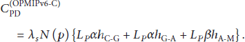
5.4.2. OpenFlow-Based Mobility Management
The basic mobility signaling of OMM, 
The flow modification cost per switch is the same as (2). The signaling cost of OMM 
At handover, OMM controller only sends FMOD to switches between nAS and CS. Thus, 
5.5. Basic Handover Process
We exploit the definition for the handover latency
The parameter for handover in Table 2 is referenced from [5, 16]. The handover latency for the handover process 
The parameter for handover latency.

The value of
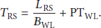
The RS message is then sent over the wireless link between the MN and the access switch. In this case, it is assumed that there are no wired or wireless link failures, and we also do not take any authentication procedures into consideration.
5.5.1. OPMIPv6-C Handover Latency
OPMIPv6-C does not use PMIPv6 signaling. It only uses the extended OpenFlow signaling through a secure channel over TCP. Thus, 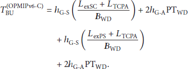

5.5.2. OMM Handover Latency
OMM is almost similar to OPMIPv6-C. Thus, 
5.6. Cost Analysis Results
In this chapter, we explained the signaling cost analysis results for OPMIPv6-C and OMM. We set the default values of the system parameters for the cost analysis as
The signaling cost versus υ is shown in Figure 7. We set the parameters R as 400 m and set the parameters of υ to 0 m/s and 100 m/s. The signaling cost is directly proportional to υ, and the signaling cost of OMM is almost identical to that of OPMIPv6-C. The reason of difference is only in the packet header size of the RA and exPS. If OMM used exPS instead of RA, they would have had the same signaling cost.
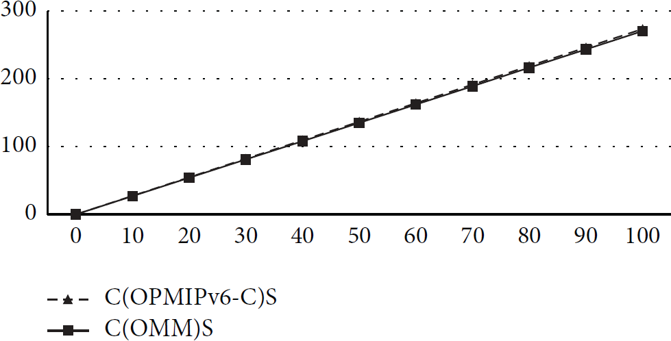
Signaling cost versus υ (
Figure 8 shows the signaling cost versus R. We set the parameter

Signaling cost versus R (
Figure 9 shows the signaling cost at handover versus
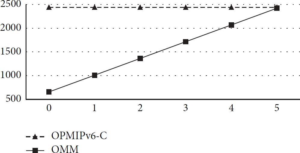
Signaling cost at handover versus
Figure 10 shows the packet delivery cost versus

Packet delivery cost versus
Figure 11 shows the total cost versus

Total cost versus
5.7. Handover Latency Analysis
The system parameter values for the handover latency were
Figure 12 shows the handover latency versus

Handover latency versus
6. Conclusion
We are proposing OMM, which is an adaptation of PMIPv6 concept to SDN architecture. In order to support mobility in SDN architecture, the mobility functions are unified from the separated PMIPv6 entities to MME. The proposed scheme only uses OpenFlow signaling and PMIPv6 concept. Also it is focused on the data structures for the mobility service, detailed procedure, and efficiency path setup mechanism. The result of the performance evaluation indicates that the proposed scheme is efficient compared to OPMIPv6-C at the handover phase.
Footnotes
Conflict of Interests
The authors declare that there is no conflict of interests regarding the publication of this paper.