
Abstract
An underwater acoustic communication channel is time varying and has multipath propagation with bottom and surface reflection. A rake receiver has time diversity effects in multipath propagation environments. We have to recognize the correct path for a rake receiver, as this affects communication performance in the underwater acoustic channel. In this paper, we propose a more reliable rake receiver based on BER (bit error rate) of training sequence duration. We conducted simulations and lake trials to evaluate the performance of the proposed method. When the channel coding technique was not applied, the uncoded BER performances of the proposed method, the conventional method, and the nonrake method in the lake trial were 0.016, 0.088, and 0.141, respectively.
1. Introduction
Underwater sensor networks (USNs) can be used for environment monitoring, disaster prevention, and military surveillance [1–5]. Unlike terrestrial communication, underwater acoustic communication utilizes sound waves, and underwater acoustic channels are a time varying channel environment. The sound speed, which is slower than radio waves, is dependent on the water temperature and the salinity. The sound transmission path is changed by refraction according to the gradient of vertical sound velocity [6]. When sound waves are passed through the underwater, they are affected by attenuation, ambient noise, and multipath propagation effect including reflection of bottom and surface. For the purpose of improving reliability in an underwater acoustic channel, rake receiver has been used for time diversity, which utilizes multipath propagation.
In practice, rake receiver techniques have been used for time diversity in underwater acoustic communication. Considering the multipath propagation occurs when the signal is transmitted, the rake receiver was implemented with a certain number of fingers, used for correlation of the signals received on different paths and with different delays. It is possible that the finger is a structure demodulating a signal of each path. The role of the receiver is to combine such multipath signals to obtain a single output signal [7–9]. If the received signal is passed through the matched filters, then the energy peaks would emerge in accordance with the number of paths. In this method, the weighting values of each path are dependent on the path gain. However, it may be that the rake receiver is incorrect because influence about channel is difficult for each path from time-variant channels in the process of synchronization. So the demodulated results of signals can get high error rate. This leads to reduced performance of BER (bit error rate). The matched filter output peak of the path is so high that the synchronization point is incorrect in underwater acoustic channels. This could cause high weighting values to be assigned to incorrect paths. The above cases make reliable underwater acoustic communication difficult.
In this paper, we propose a rake receiver based on BER of training sequence duration. To prevent the assignment of a high weighting value to incorrect path symbols, the method that uses the BER of training sequence duration was applied. The conventional rake receiver allocates weighting value in accordance with matched filter output amplitude called path gain [10]. However, the proposed rake receiver assigns weighting value in which low BER of training sequence constitutes a high weighting value. Since it compensates channel environments of each path using training sequence, better BER performance than previous method can be derived. The applied modulation method is BPSK DSSS (binary phase shift keying direct sequence spread spectrum) for rake receiver [11]. A simulation based on the bellhop modeling and lake trial was carried out to compare the performance of the proposed rake receiver with a conventional rake receiver and a nonrake receiver.
The remainder of this paper is organized as follows. Section2 first presents the conventional rake receiver technique, and Section3 presents the proposed rake receiver based on BER of training sequence duration. In addition, we present the frame formation and receiver structure for proposed rake receiver. Section4 applies the proposed method to the simulation and experimental data. Finally, Section5 provides a summary and draws conclusions.
2. Conventional Rake Receiver Technique
In underwater acoustic communication, the signal can reach the receiver via multiple distinct pathways. The rake receiver is used to correct this effect, selecting the stronger signals. Each of these multipath components in rake receiver is called finger. The matched filter can detect signals by minimizing noise and maximizing energy in the received signals [11,12]. For the purpose of detecting signal starting point, the matched filter is made of training sequence. If we assume that there are three paths for a simple simulation, the matched filter output is as shown in Figure1.

Matched filter output.
As shown in Figure1, when a threshold value is 0.4, there are three peaks of matched filter output that are higher than a threshold value. Then, a conventional rake receiver consists of three fingers, as shown in Figure2. The block diagram for processing of a finger is shown in Figure3. Each finger consists of downconversion, LPF (Low Pass Filter), despreading, PLL (phase locked loop), and RLS DFE (recursive least square decision feedback equalizer) [13–16] and is responsible for collecting the energy of symbol. Doppler frequency estimations have been set up in each path [17–19].
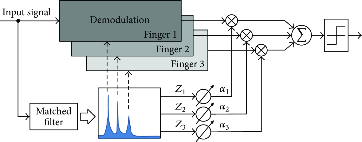
Block diagram of the conventional rake receiver.

Block diagram for demodulation of each finger.
At first, the signals were input into a rake receiver, and then the number of fingers was decided by the matched filter with a threshold value. The weighting value

A simulation was conducted, and its matched filter output is shown in Figure1. Figure4 shows graphs of the constellation that is geometric representation of signal that checks the strange effect such as phase error of each symbol. The recovered signal of each path can be represented by constellation for showing its phase error form.
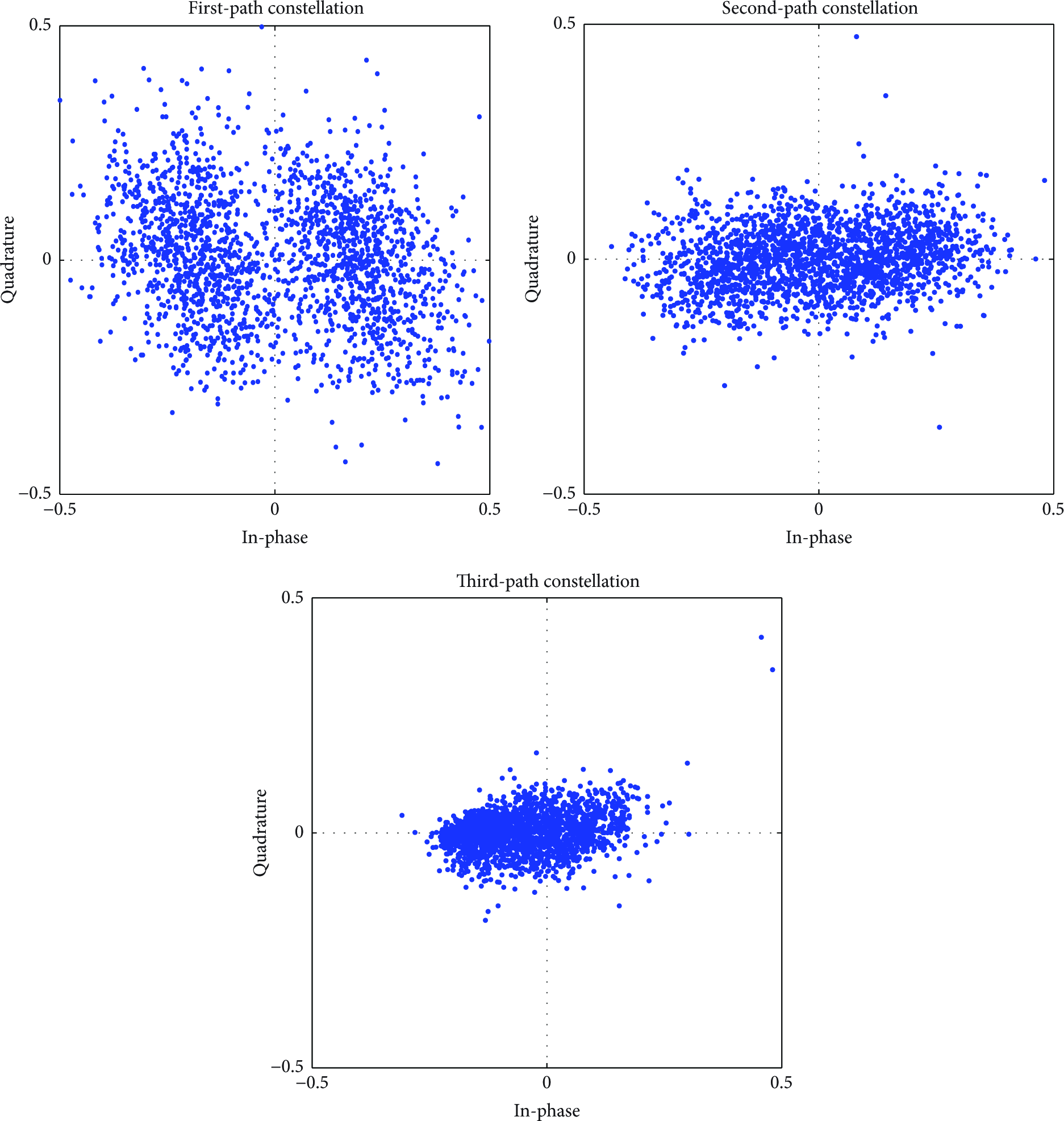
Constellation in each path.
As shown in Figures1 and4, the 2nd path is a maximum value that is matched filter output amplitude. But the constellation of the 1st path is more obvious than other constellations. In this case, the conventional rake receiver would assign a high weighting value to inappropriate path symbols, and then more noise and errors are merged in proper symbols.
3. Proposed Rake Receiver
In this section, we propose a rake receiver technique for improving communication performance in the multipath propagation environment. The conventional rake receiver technique allocates weighting values in accordance with each path gain, but the proposed rake receiver assigns weighting values depending on BER of training sequence duration. The block diagram for a proposed rake receiver is shown in Figure5.

Block diagram of the proposed rake receiver.
As shown in Figure5, the matched filter was used for path detection, which is the same structure as a conventional rake receiver. Detected path signals are recovered in each finger. Next, BER of the training sequence duration are estimated in each path by comparing recovered training bits and transmitted training bits. After introducing BER threshold, the finger of which BER of training sequence is higher than BER threshold is blocked. Equation (2) is average value of BER of training sequence duration and BER threshold equation is (3). Consider


For a weighting value in accordance with lower BER,
We present the receiver structure based on BPSK DSSS communication system using the proposed rake receiver in Figure6. As shown in Figure6, a transmitter consists of spreading by chip and SRRC (square root raised cosine) filter, which is used for reducing the intersymbol interference and upconversion. Modulated signals are transmitted through channels. A receiver consists of BPF (band pass filter), which is used for filtering of the interested frequency band, and a proposed rake receiver. In Figure6, synchronization means path detection like a conventional rake receiver. Then the number of fingers is determined by a matched filter with path gain threshold. After processing at each path, BER of training sequence duration are inspected at each path using BER threshold. Then, weighting values are calculated by making the low BER of training sequence a high weighting value. These values are put into each path, and the symbols of each path output are merged before making a hard decision.

Block diagram of the underwater communication system with the proposed rake receiver.
4. Simulation and Experimental Results
4.1. Simulation
We executed the simulation using VirTEX (Virtual Time Series Experiment) [20] based on the bellhop to evaluate the performance of the proposed rake receiver. To create the simulation environment, we used an actual sound speed profile in a lake. We assumed that the surface was flat and the bottom was slanted. The bottom information for the simulation was as follows. Sound speed at bottom was 1600 m/s, bottom density was 1.23

Simulation channel characteristic: (a) sound speed profile, (b) eigenrays, and (c) channel impulse response.
Source signal was modulated to BPSK DSSS. Spreading factor is 20 chips per bit. Bit rate was 200 bps, chip rate was 4 kcps, and carrier frequency and sampling frequency were 16 kHz and 192 kHz, respectively. We disposed of the 0.2 sec silence between training section and data section to avoid delay distortion. Several parameters for communication are given in Table1.
Parameters for simulation.

Simulations were conducted with a thousand trials in accordance with each SNR from −10 dB to 10 dB at an interval of 1 dB. The BER performance according to SNR (Signal-to-Noise Ratio) is shown in Figure8. It was shown as an average BER at each SNR. The BER performance differences of all methods are not apparent at SNR −10 dB. The BER differences are evident from −7 dB to 7 dB. Through simulations, it was found that overall the proposed rake receiver has better BER than a conventional rake receiver and a nonrake receiver. The BER of the conventional rake receiver and nonrake receiver are about 0.055 at SNR 10 dB, and by comparison the BER of the proposed rake receiver is about 0.030 at SNR 10 dB. Interestingly, the BER of conventional rake and nonrake become the same at SNR 9 dB to approximately 0.058. These phenomena are caused by detecting incorrect path or assigning a high weighting value to an erroneous path. To prevent this, the proposed rake receiver uses an assignment method based on BER of training sequence duration. In simulations, the better performance of the proposed rake receiver was attributed to detecting correct path and blocking erroneous path by using BER threshold.

Uncoded bit error rate.
4.2. Lake Trials
We executed the experiment during April 2015 in a lake to evaluate the proposed method. The setup for lake experiments is shown in Figure9. The water depth of the experimental area was about 40 m. A projector and a hydrophone were located at 4 m and 15 m below the surface, respectively. The projector was a Neptune D/17/BB while the hydrophone was a B&K 8106. A power amplifier was used to transmit signals as 10 dB. Distance between projector and hydrophone was approximately 340 m.

Setup for lake trials.
The source signal has the packet as described in Table2. The carrier frequency is 16 kHz, while sampling frequency is 192 kHz. Channel coding is not applied to the signal. Before transmitting the communication signal, we got the channel impulse response using LFM (linear frequency modulation) signals shown in Figure10 and the scattering function using the modulated M-sequence as shown in Figure11. We confirmed that Doppler frequency was about 1.3 Hz.
Parameters for lake trials.


Channel impulse response.

Scattering function.
As shown in Figure12, there were six paths in received signals where normalized path gain threshold was 0.4. The BER of training sequence duration at each path are shown in Table3. After BER threshold had been calculated using (3), its value was proved to be 0.0565. Then paths below BER threshold were used in proposed rake receiver; these path numbers were 2nd, 5th, and 6th path. Therefore, there are three fingers in the proposed rake receiver.
BER of training sequence duration in accordance with each path.


Matched filter output of lake experiments.
We got the uncoded BER in order to compare the performance of the proposed rake receiver with the conventional rake receiver and nonrake receiver. As shown in Figure13, the constellation of the proposed rake receiver was more obvious than the others. Figure14 shows the uncoded BER. The data packet consists of 512 symbols (512 bits). We can show that the BER of the proposed rake receiver was better than that of the conventional rake receiver and nonrake receiver. The uncoded BER performance of the proposed method is approximately 0.016, while that of the conventional method is about 0.088 and that of the nonrake method is 0.141.

Constellations in lake trials: (a) proposed rake receiver, (b) conventional rake receiver, and (c) nonrake receiver.

Uncoded BER comparison.
5. Conclusions
In underwater acoustic communication especially in shallow sea environment, occurring multipath propagation is unavoidable. The multipath propagation decreases the transmission efficiency and distorts the source signal. The conventional rake receiver had used path detection method by path gain. In this paper, we proposed a more reliable path detection method based on BER of training sequence duration. In experiments executed in a lake, we confirmed that the proposed rake receiver resulted in low uncoded BER. We compared the performance of the proposed rake receiver with the conventional rake receiver and nonrake receiver in the simulation environment and lake experiments. In simulation, the uncoded BER difference between conventional rake receiver and the proposed rake receiver was about 0.025 at SNR 10 dB. In lake trial, the uncoded BER difference between conventional rake receiver and the proposed rake receiver was about 0.007. We showed that the uncoded BER of the proposed rake receiver was lower than that of the conventional rake receiver and that of the nonrake receiver. The incorrect path in a conventional rake receiver and a nonrake receiver aggravated the performance, whereas the proposed method showed better performance with correct path detection using BER of training sequence duration.
Footnotes
Competing Interests
The authors declare that there is no conflict of interests regarding the publication of this paper.
Acknowledgments
This work was supported in part by Hanwha Corporation.