
Abstract
Sensor web systems, cyber-physical systems, and the so-called Internet of Things are concepts that share a set of common characteristics. The nature of such systems is highly dynamic and very heterogeneous and issues such as interoperability, energy consumption, or resource management must be properly managed to ensure the operation of the applications within the required quality of service level. In this context, base technologies such as component based software engineering or Service Oriented Architecture can play a central role. Model driven development and middleware technologies also aid in the design, development, and operation of such systems. This paper presents a middleware solution that provides runtime support for the complete lifecycle management of a system consisting of several concurrent applications running over a set of distributed infrastructure nodes. The middleware builds up on top of a general purpose component model and is driven by a quality of service aware self-configuration algorithm that provides stateful reconfiguration capabilities in face of both internal (application triggered) and external (application unaware) reconfiguration events. The platform has been deployed over an automated warehouse supervision system that serves as a case study.
1. Introduction
Several paradigms have emerged over the last decade with similar characteristics and challenges. Internet of Things (IoT), cyber-physical systems (CPS), and sensor web systems demand a common set of characteristics such as geographical distribution, interoperability, dynamicity, or system heterogeneity. Aspects such as quality of service (QoS) and resource management are particularly relevant in this kind of systems, as far as they affect user experience and energy efficiency [1–3]. To cope with these issues, different technologies have been proposed. Component frameworks and Service Oriented Architecture (SOA) were initially developed to provide system decoupling, promote code reuse, and ease application deployment. But the existence of other requirements such as runtime reconfiguration [4,5] or QoS assurance [6] has highlighted the need to integrate other technologies.
More specifically, this work is focused on systems formed by heterogeneous infrastructure nodes (in terms of hardware and operating system) that dynamically allocate component based stateful applications which are as well diverse in terms of implementation language, communication protocols, and QoS requirements. An example of such kind of systems is detailed in Section6, where an automated warehouse composed of tens of heterogeneous hardware nodes and hundreds of software components needs to be supervised in real time in order to avoid downtime due to new application deployment or to unexpected component faults which would be otherwise difficult to diagnose. Such distributed system is composed of several distributed (legacy) applications that use heterogeneous communication protocols. The proposed middleware supervises the complete system, provides fault tolerance support for specific critical components, and aids in the registration and deployment of new system configurations.
Several key challenges arise from such needs, namely, (1) the adoption of a suitable component framework, (2) the support for dynamic reconfiguration, and (3) the management of the system resources to provide the required QoS level to the demanding applications. This work proposes a middleware solution that addresses these challenges. It inherits the advantages of a standard component model such as SCA [7] and extends it to provide the required QoS aware reconfiguration support. The proposed QoS characterization is inspired in [8]. It has been adapted to support component based distributed applications, extending it to model additional aspects as state or distribution. The concepts of service and service implementation [9] have inspired the concepts of logical component and physical component. The middleware architecture is the result of previous work [10,11], as well as the low level QoS management mechanisms [12,13], the definition of the basic services [14], and the basic fault tolerance mechanisms for the middleware components [11,15]. This paper is focused on the QoS aware dynamic reconfiguration algorithm proposed in Section5. An approach to implement a fault tolerant distributed state recovery mechanism is also described in Section6.
The middleware support that is proposed in this paper extends the DAMP (Distributed Applications Management Platform) platform introduced in [16], which provided basic lifecycle management support for component based distributed applications, as well as node level (local) QoS enforcement in face of components self-QoS reconfiguration requests. This work goes further and proposes a holistic approach to the entire system QoS enforcement through specific resource management policies, considering the application as a unique entity that shares the available resources with the other applications that are running on the system. This overall QoS enforcement of the demanding applications takes into account the functional dependency between application components, alongside their QoS requirements and actual node allocation. Also, the eventual availability of redundant component replicas in alternative hardware nodes is also considered.
More specifically, self-reconfiguration mechanisms to support stateful system reconfiguration in face of external (application unaware) as well as internal (application triggered) reconfiguration events are proposed. These mechanisms rely on four specific functionalities provided by the extended DAMP platform, that is, (1) infrastructure resource monitoring, (2) application state monitoring, (3) a reconfiguration API, and (4) a QoS aware reconfiguration algorithm, the latter being the main contribution of this work.
The infrastructure resource monitoring updates the system database with actual node utilization and liveliness information, thus enabling the detection of eventual node overload and physical faults. The application state monitoring collects actual component execution and response times. This way, component crash or deadline miss events can be detected and managed. The system reconfiguration API provides a way for the application components to trigger functional events such as self-QoS change requests and also allows the system operator to issue application start and stop operations into the system. Therefore, the monitoring capabilities of the middleware enable the detection of external (nonfunctional, application unaware) reconfiguration events, while the reconfiguration API can be used by already running applications to trigger internal (functional, application specific) reconfiguration events. Finally, the QoS aware reconfiguration algorithm allocates the available infrastructure resources to the demanding applications, taking into account their QoS related requirements. This set of functionalities enables the runtime support for the complete lifecycle management of distributed and dynamically reconfigurable component based stateful applications.
The rest of the paper is as follows: Section2 presents a brief survey of research works that focus on dynamically reconfigurable systems and QoS support. Section3 depicts the overall middleware design, its architecture, and the description of the provided services. Section4 describes the components, applications, and infrastructure that compose the system model, with special attention to its QoS characterization. Section5 details the mechanisms that enforce the applications QoS when a dynamic system reconfiguration is triggered. Section6 describes the mechanisms that enable a stateful system recovery and Section7 presents a case study that builds a distributed supervision system of an automated warehouse, upon some of the most representative functionalities of the middleware presented in this paper. Finally, Section8 presents the conclusions and points out future work.
2. Related Work
A component framework usually comprises a component model and a set of related tools and methodologies that aid in the overall process of application development lifecycle, from initial specification and design, through development, deployment, runtime support, and maintenance. Nevertheless, not all the component frameworks cover all these steps. This fact, alongside their different level of abstraction, tool support, or scope, hinders the process of selection of a suitable one for a specific need. In this sense, [17] presents a good classification framework that eases the selection of a component model. In previous works [7,16] several component frameworks were analyzed, and Service Component Architecture (SCA) was adopted as the most suitable one for the considered target systems: on the one hand, the availability of different (commercial and open source) implementations of the standard and the annotations based nature of the component model makes the adaptation of legacy code relatively easy. On the other hand, the standard provides native support for diverse communication protocol bindings. Thus, the required requirements related to flexibility, interoperability, and system heterogeneity are addressed by the adoption of a standard component model such as SCA.
With respect to the reconfiguration capabilities, most of the considered component frameworks consider only static reconfiguration support. It means that an application must be stopped before reconfiguration is accomplished and then restarted. This is the case of SCA standard itself, which relies its configuration capabilities on XML configuration files and an architecture description language (ADL) that defines the application components interfaces and bindings at design time. But as far as authors know it does not define (nor does, e.g., Wright, Darwin, or ACME [18]) any runtime environment for managing its architectural entities during runtime. Opposite to that, some other component models provide support for dynamic reconfiguration, for example, SOFA [19] or FraSCAti [20], which exploits its fractal nature to provide a dynamically reconfigurable SCA implementation. However, regarding QoS support, none of these general purpose component frameworks offered it natively.
None of the analyzed general purpose component frameworks offer native QoS support. Thus, the rest of this section revises several research works that are focused on the QoS and resource management of dynamically reconfigurable systems. Generally, these works usually consider abstract component models oriented to the simulation and testing of reconfiguration strategies. Table1 summarizes the main features of these related works.
Related work feature comparison.

In [4,6], Li provides a good state of the art focused on the QoS assurance during the reconfiguration of component based systems. In this case, QoS assurance is meant to reduce “application disruption” to the minimum during the reconfiguration phase. In other words, the objective is to avoid, as far as possible, that a reconfiguration could affect the ongoing transactions, minimizing as well the system downtime during reconfiguration. To support stateful reconfiguration, it introduces the concept of versioning; that is, old and new components are allowed to coexist at the same time during reconfiguration. This approach is not valid for our needs as far as it covers only planned reconfigurations, and the problem of stateful system reconfiguration due to faults as, for example, node crash is left open. On the other hand, Li proposes shared memory to improve the timing performance when the size of the state to transfer is high. Although this is a high performance solution, it does not support distributed state, which is a key issue when the state must be transferred from one component to its replica in case of node fault.
Other works [9,21,22] are focused on the optimization of application graphs of service based applications. They consider resource related QoS characteristics (CPU, memory) as well as application specific QoS parameters (e.g., frames per second or resolution in video applications). In the latter case, application specific components are needed in order to assist the middleware in finding the most suitable solution. These works consider reconfiguration of stateless services in the context of an application and try to choose the most suitable service implementation based on a set of QoS characteristics, although the functional reconfiguration process of the service bindings (links) is not detailed. A resource manager is presented, which is able to manage events like overload or node failures, although the specific mechanisms to detect such faults are not detailed. In [21], a composition algorithm based on a QoS characterization similar to DAMP is presented, although it only considers stateless services. The selection of service implementations is optimized according to different criteria (e.g., application end to end deadline), but nevertheless, the approach is different to DAMP. For the same functional service, it considers different service implementations to represent different QoS demands. These service implementations, once deployed, have a fixed set of QoS parameters. Opposite to that, DAMP considers elastic QoS parameters for stateful components, which can be tuned or configured at runtime depending on the specific resource needs or availability. In [22] the iLaser component model is presented, which includes a control port for QoS reconfiguration purposes. In this sense, DAMP follows a similar approach but extends the control port to support state transfer. Additionally, DAMP adopts a standard component model (SCA) and thus can integrate existing legacy code in a relative easy way and can benefit from existing protocol bindings. Such issues are not covered by iLaser. In [23] stateful applications are considered in the context of a Java based component framework: while local stateful reconfiguration is supported, it does not address the distributed state problem, which is left open.
In [8] the concept of local utilization bound (LUB) supports online schedulability analysis due to its low computational cost. It achieves such good performance because it allows reconfiguration limited to a well-known set of system configurations that have been previously analyzed offline. It is task oriented and thus does not consider the notion of component, but it has served as an inspiration for DAMP, which takes some of the ideas and leverages them to consider interdependent component based distributed applications.
The SLAstic component framework is presented in [24,25], which adopts the Palladio component model and considers three aspects of dynamic reconfiguration: resource (node) allocation/deallocation, component migration, and load (un) balancing. Its objective is to optimize existing hardware resources (either avoiding underutilization in case of small work or load balancing in situations of stress), while the SLA (service level agreement) is met. The resource management algorithm functionality is specified, although it is not detailed. No specific mechanism to support distributed state transfer is detailed.
In [26–28] a CORBA (Lightweight CORBA CCM component model) based middleware is presented. It allocates physical (CPU, memory, and network) resources to application components. It depicts a multilayer resource manager (MLRM) that is composed of several modules which provide similar functionalities to DAMP, for example, resource monitoring, admission control, or composition algorithm. It considers QoS aspects such as survivability, predictability, or security but does not detail the low level mechanisms to achieve such characteristics. Through a resource management API detailed in [26], client applications can ask for resource availability and reservation. Nevertheless, it does not natively provide a specific resource management algorithm, which could be integrated by the user. On the other hand, CORBA is not being extensively used in the industry, and its application scope is quite small [29]. In [30] an improvement of the CORBA D&C standard is presented, centered in the deterministic deployment and activation of CORBA based applications, although it does not support any dynamic resource management.
Another component framework with infrastructure resource management support is presented in [31]. It considers service resource demand contracts to manage the available infrastructure resources. Due to its service oriented nature, stateful components are not considered.
In [32], a framework based on Grid Component Model (GCM) is presented. GCM is an adaptation of fractal for large scale distributed computing. Similar to DAMP, it is based on loosely coupled active objects called “autonomous components,” each allocated to an independent Java virtual machine. It does not support QoS related issues and does not detail any specific mechanism to support distributed state transfer in case of node faults.
Reference [33] details a real time oriented component framework in which sequential execution is orchestrated by a central manager. It provides determinism and reduces overhead and component coupling, but it does not support dynamic reconfiguration.
In [34] the state transfer is application specific; thus the application components must provide methods to let the middleware get a component state and inject it into its replica. A similar approach is presented in [35]. In this sense, DAMP provides a generic way to let a component write its state into the middleware database and also to read from it when a component replica must be instantiated and initialized.
3. Design of Distributed Applications Management Platform (DAMP)
Figure1 depicts the overall system deployment model [16], containing several applications running in a set of distributed nodes. Both the middleware components and the application components are represented. Different application components are represented with different colors. Over an infrastructure of n nodes, there is one middleware daemon component for each node that allocates application components. This daemon receives orders from the middleware manager, who is responsible for the whole system management.
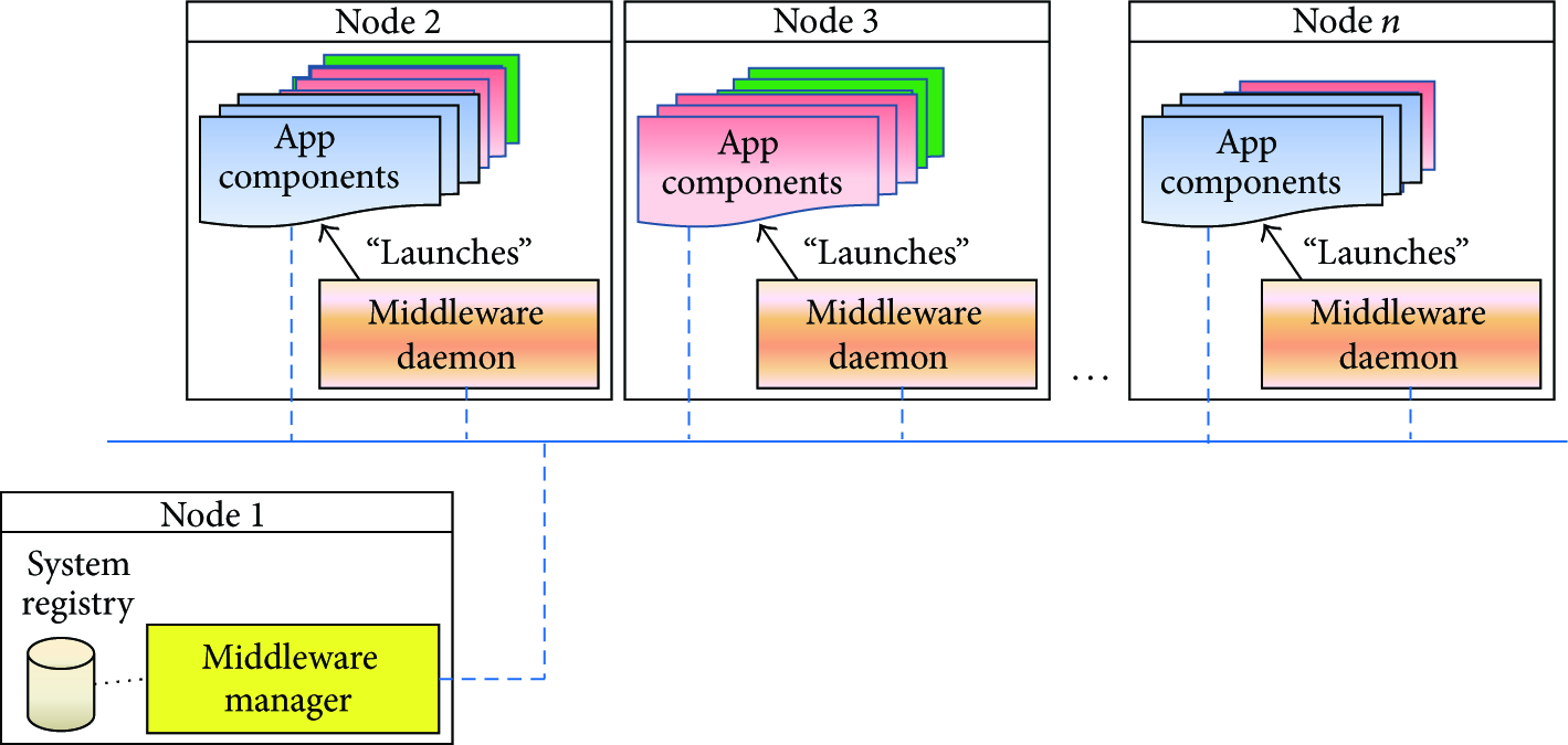
System deployment model.
The different application components, alongside their QoS specifications and node allocation, are registered in the system registry database. The middleware manager receives monitoring information about the components state from the distributed daemons and stores it in the database. This information can be used to implement fault tolerance mechanisms with stateful system recovery support.
3.1. DAMP Architecture
The interrelationship between the middleware components and the application components is depicted in Figure2. The middleware manager integrates the system registry database and exposes several services to manage the system. The applications, alongside their logical and physical components explained in Section4, are registered in the system database through the registry service exposed by the middleware manager. The middleware manager also provides a monitoring service to receive the state information of the distributed components, which is sent by the middleware daemons. The execution control service provides a way to control the application instantiation and execution. Finally, through the QoS configuration service, the application components can issue self-QoS (application triggered) change requests. These services are shown in red in the left side of the middleware manager, and their interfaces are described in Section3.2.

Links between an application component and the middleware.
The execution control operations are transferred either to the middleware daemons (component launch reference) or to the application components (init, start, stop, and QoS change operations) through the manager right side execution control reference (see Figure2). An application component transfers its state information to its middleware daemon through the state monitoring reference. The middleware daemon packs the info from all components inside its node and sends it to the middleware manager, which updates the system database accordingly.
To reduce to the minimum network bandwidth and latency due to middleware internal communications, a high performance SCA binding over Data Distribution Service (DDS) was designed and implemented in [12]. All the middleware related communication between the platform ports is performed over the DDS binding.
3.2. DAMP Services
As stated in previous section, DAMP provides several services to the system operator and the running applications. The registry and the execution control services can be used by the system operator to register new applications into the system and manage them at runtime. The monitoring service is for internal use; that is, it is used by the middleware for fault tolerance and QoS management purposes. Finally, despite the QoS configuration service the applications can trigger functional self-QoS reconfiguration events. Next, these platform services are explained in deeper detail.
3.2.1. Registry Service
This service is oriented to the system administrator and provides a way to register the applications alongside their components into the system registry database. In order to ease the integration with external client applications such as system management consoles or MDE tools such as the one described in [36], it is exposed as a SOAP web service, although it could be exposed over any other SCA binding available (e.g., REST, RMI, or JMS). The registry service is represented by the following interface:
String InstallApp (String name, String InstallLogicalComponent (String app_ID, String name, String InstallPhysicalComponent (String lc_ID, String name, String node_ID, String path, }
The registration process starts with the registration of an application, indicating if the application start and stop operations must be synchronized or not. If the application is declared as synchronized, each application component is started in the order specified by the startOrder and stopOrder arguments. For each application logical component, one or more physically deployed components can be available, as replicas for fault tolerance or load balancing purposes. The concepts of logical and physical components can be assimilated to the terms service and service implementation utilized in [9], with some differences. In the scope of this work, the term logical component differs from the concept of service, as far as it can be stateful. Also, a service implementation has a fixed execution time once deployed in a specific node, while a physical component is characterized by a vector of possible execution time discrete values. Section4 details this system model characterization.
3.2.2. Execution Control Service
This service enables the instantiation, initialization, start, stop, and destroy operations over an already registered application, as well as QoS reconfiguration of specific application components. It is built upon three different services, namely, (1) a service implemented by the middleware manager, (2) a service implemented by the middleware daemon, and (3) a service implemented by base class from which all application components inherit. The first one can be accessed by the system administrator, for instance, through an external client management console. As the registry service, it is exposed as a SOAP web service. The instantiation of each application component is performed through the middleware daemon through the second service, which actually launches the Java process that allocates the component. Afterwards, the middleware manager directly invokes the third service, which is implemented by the component base class and defined by the IControl interface:
}
This service actually performs the initialization, start, stop, and destroy operations over an application physical component. Also, dynamic component QoS reconfiguration can be performed invoking the SetQoSParams function of this service, which accepts as an argument a QoSParams data structure containing the period, deadline, and execution time vectors of the component.
3.2.3. Monitoring Service
The monitoring functionality is distributed between two different services. One is implemented by the middleware daemon and is invoked by the application components residing in the same node, which sends their monitoring information to their localhost middleware daemon. The other service is implemented by the middleware manager and invoked by the distributed middleware daemons, which collect the monitoring information of their application components and resend it to the manager. This monitoring data includes liveliness, state, and actual execution time and response time information and is periodically updated by the application components. Thus, this service enables stateful system recovery in case of node failure or component malfunction detection.
3.2.4. QoS Configuration Service
An application can ask for a self-QoS change request through this service. This is considered an application triggered QoS reconfiguration, and it is performed in two steps. First, in response to an application specific event, a self-QoS change request is issued to the middleware manager through the IQoSConfig interface:
}
where the T, D, and C function arguments represent here the ordinal values of the respective T, D, and C vectors of each of the components belonging to the application. The QoS change request is thus defined by a set of specific values of T, D, and C for all the components of the application.
Once the new desired QoS parameters are defined, the QoS aware reconfiguration algorithm exposed in Section5 searches for an alternative system configuration to satisfy the application QoS change request. To find a new feasible system configuration that meets the overall system requirements, the middleware manager could decide to reconfigure the T, D, and C values of those running components which have elastic QoS parameters. This second step can be performed thanks to the IControl service explained in Section3.2.2, which is implemented by the components base class. As an example, consider a video surveillance system that must increase its fps (frames per second) parameter in case an intrusion detection alarm is fired. In absence of alarms, the video component is configured at 10 fps, in order to reduce CPU consumption to a reasonable minimum. But in case of intrusion detection, the system is programmed to automatically increase video quality to 25 fps. Therefore, the component asks for a self-QoS change request, more specifically a change in its execution period, from the initial 100 ms corresponding to a 10 fps quality, to the required 40 ms (25 fps). This implies an increase in the resource demand for the application and must be properly managed by the QoS reconfiguration algorithm explained in Section5.
4. System Model and QoS Characterization
4.1. DAMP Component Model
A DAMP component is basically a SCA component that has been extended with several control ports (one service and two references) to enable the control and monitoring features of the middleware. Every DAMP component inherits from a base class these control ports. Thus the application developer can focus on the implementation of the functional aspects of the component, depicted in Figure3 as business services and references, following the SCA terminology.

Application component interfaces.
The base class of a DAMP component implements the IControl service to let the middleware control the execution of the component as well as inject the component state and tune its QoS parameters (T, D, and C). It should be noted that C depends on the specific hardware node the component is executing on. Moreover, the component could be asked to execute in different QoS modes that imply different C values. For instance, a video component could be configured in high versus low resolution mode.
On the other hand, a DAMP component utilizes the IMonitor reference to communicate its internal state to the middleware, as explained in Section3.2.3. Finally, the IQoSConfig reference is available to ask for eventual functional (application triggered) self-QoS reconfiguration.
Regarding the dynamic model, the state machine of a DAMP component is shown in Figure4. Through the registry service (see Section3.2.1), a component is registered in the system registry database and deployed in a specific node. Then, it can be launched (instantiated and loaded in memory) by the middleware daemon in response to an order issued through the execution control service (see Section3.2.2) exposed by the middleware manager. Once loaded, it can be initialized with specific state and set of QoS parameters. Finally, from this state, the component can be started.

State machine of a DAMP component.
When a periodic component is started, a cyclic execution of the activity diagram shown on the right side of Figure4 is initiated. This loop is executed with the period that has been specified in the initialization stage and exits when the middleware kindly asks the component to stop through the _MustStop flag. This flag allows for application driven resource disposal, but the middleware also provides an alternative way to force the emergency removal of misbehaving components. This emergency exit is performed by the middleware daemon through operating system services.
The loop of the periodic thread first executes the functional code of the component invoking the computeFunctionalCode abstract function from the base class, which computes the outputs from the available inputs that have been issued to the component through the component business services pointed out in Figure3. Then, the thread invokes the writeOutputs abstract function, which invokes the component business references if any. Both abstract functions are implemented by the component developer. While the input variables of the component are provided through its business services, the output variables are mapped to the component references through the writeOutputs function implementation. It should be noted that both mappings are likely to be automatically generated by a MDD tool (see [36]), although this aspect is not covered in this work.
4.2. System Model
The system model for QoS characterization presented in [16] has been refined to include the concept of logical component. As stated in Section3.2.1, [9] proposes a similar approach with the concepts of service and service implementation, although here the concept of logical component is inherently stateful and the QoS parameters can be tuned between certain admitted values. In the scope of this work, a logical component is a functional component that can be deployed in one or more physical nodes. Once deployed, it becomes an actual physical component. When a logical component is deployed in multiple nodes, it is said to be a replicated component. This eventual redundancy can be considered for fault tolerance or load balance purposes.
The system registry database represented in Figure1 stores the QoS model of the system. It considers a set of nodes N (see (1)) that allocate a set of distributed applications A (see (2)). The cardinality of sets N and A is denoted by 


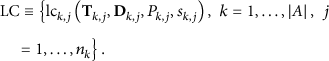
Each logical component has its own QoS parameters (period T, deadline D, and priority P). P denotes the QoS priority (criticality), established by the system operator at the configuration stage, and affects the local feasibility tests performed by the QoS reconfiguration algorithm described in Section5. QoS level 1 (low): QoS level 2 (high): 

Each logical component can be deployed in one or more hardware nodes (e.g., for fault tolerance purposes). Once deployed, it is redefined as a physical component and acquires an extra QoS parameter associated with the specific node in which it is deployed, that is, the execution time
Additionally, actual physical component response time is monitored at runtime and stored at the database, thus enabling deadline loss monitoring and component malfunction detection.
The set of physical components 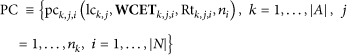

It should be noted that the allocation of logical components to specific nodes in the registration phase (see Section3.2.1) implicitly considers other parameters that are related to infrastructure. For instance, if a component provides encryption services, it should be allocated to a hardware node that supports such kind of encryption through, for example, a TPM (Trusted Platform Module). Other infrastructure related aspects could include operating systems, special hardware (e.g., webcams, sensors, and field buses cards), or memory.
5. QoS Aware Resource Management
5.1. Resource Manager Design
An initial version of the DAMP QoS manager was introduced in [16]. In this paper, the QoS management process is explained in deeper detail. The problem formulation has been extended to cover the end to end latency of the applications and the QoS interdependencies between the applications running in the system.
The QoS assurance of the applications that are running in the system is directly related to the management of the resources provided by the infrastructure nodes. The middleware manager includes a resource manager that allocates available resources to the applications, taking into account their QoS demand and priority (criticality). This means that if a high priority component must be launched in a specific node that already allocates a low priority running component, the resources assigned to that lower priority component could be reduced in case of shortage of CPU resources. In this sense, the lower priority component could suffer a controlled QoS degradation inside its allowed values of T and C. In the most extreme case, a controlled shutdown of the low priority component could be necessary.
The reconfiguration events that trigger the execution of the resource manager can be either functional or nonfunctional. The events triggered by the system operator or by an application (e.g., start/stop operations or component self-QoS change requests) are considered functional events. The nonfunctional reconfiguration events are triggered by the middleware itself, in response to QoS loss detected by the monitoring service. These events are usually due to nonplanned events such as node crash or application component malfunction (e.g., an application component consumes much more resources than those specified in its registration).
In face of both functional and nonfunctional reconfiguration events, the platform follows a predefined QoS management policy to allocate the available resources to demanding applications. This policy is implemented in the composition algorithm, which can be interchanged to meet specific needs, for example, optimize the energy consumption, or maximize the system performance. The default implementation considers the applications criticality (QoS priority) when proposing a configuration for the components QoS parameters (T, C). The feasibility of the proposed configuration is verified through a local schedulability test. Figure5 depicts the relation between the resource manager, the composition algorithm, and the schedulability test modules. In this work the schedulability test is based on the response time analysis (RTA) [38].

Architecture of the QoS manager.
5.2. Proposed Composition Algorithm
A simplified activity diagram of the process following a system reconfiguration event consisting of an application (

Composition algorithm.
In the best case, the new application could be started without reconfiguring the QoS of existing applications. In the worst case, the application could be rejected due to lack of resources. In the middle, a compromise solution could be found, lowering the QoS of lower priority applications to an affordable level. The job of the composition algorithm is deciding if the new application may be launched at the required level of QoS and, if so, finding a feasible QoS configuration for the overall system in the minimum time.
To achieve this, the composition algorithm performs the process detailed by Algorithm1. To better understand the algorithm, the following key considerations should be noted:
The application to be launched is defined as a set of logical components with a required set of specific values for their QoS parameters, denoted by the scalar values T, D, P. The WCET value for the physical components associated with these logical components has also a desired scalar value. The feasibility test (RTA) is executed in the context of a specific node and takes into account all the already active (running) components in the node and those components marked as “requested for launch” by the composition algorithm. The feasibility test returns the estimated node utilization factor if the node configuration is feasible, or a “nonschedulable” error code if not. The eventual QoS reconfiguration of components that are already running is performed in a strict order of QoS priority, performing a controlled QoS degradation, or even a shutdown, of the less critical applications. The desired QoS parameters for the application components to be launched implicitly define the maximum affordable end to end deadline required for the different processing chains of the application. To better understand this, consider the example video application

/ S_alone = createPhysicalComponentSubset(ak, alone, not replicated) PC._requestedForLaunch = true setQoSConfigForNode(PC) / PC._feasible = true saveQoSConfigForNode(PC)
/ S_not_replicated = createPhysicalComponentSubset( PC._requestedForLaunch = true / excludeFeasibleComponents(S_alone, PC._node) setQoSConfigForNode(PC) / PC._feasible = true saveQoSConfigForNode(PC)
/ S_replicated_not_alone = createPhysicalComponentSubset( PC._requestedForLaunch = true / excludeFeasibleComponents(S_alone, PC._node) setQoSConfigForNode(PC_node) / PC._feasible = true saveQoSConfigForNode(PC)

Application composed of five logical components (one of them having two physical components).
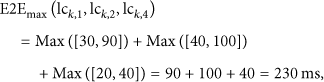
Suppose that the set of logical components is defined as
}
while the set of physical components is
}
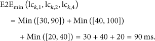
In this case the worst case end to end deadline for the processing chain that starts at the ImageCapturer component and finishes at the ImageViewer is calculated as
Taking into account these considerations, Algorithm1 depicts the proposed composition algorithm pseudocode. This algorithm tries to optimize the search time for a feasible solution while implementing the discussed QoS priority based resource management policy. The algorithm performs three steps sequentially.
In the first step (STEP 1), the S_alone subset is calculated. It includes the application physical components, replicated or not, that do not have neighbor components belonging to the same application; that is, in the scope of the application, they are isolated in a specific node. Every component belonging to S_alone is marked as “requested for launch” and feasibility of each of them is verified. This way, if any of them is not feasible, the process stops in an early step and the application is rejected, thus optimizing the algorithm computation time. To verify the feasibility of these components, an RTA schedulability test is executed for each node that allocates such components, taking into account the currently active components (belonging to other applications) plus the new “requested for launch” component. If the first RTA schedulability test fails, it means that a QoS reconfiguration for (some of) the current active components would be necessary. This is only possible if the QoS priority of such components is lower than the QoS priority of the component to be launched. In such case, a new QoS configuration is proposed, decreasing the QoS of the lowest priority components.
This loop is executed until a feasible configuration is found or the space of QoS reconfiguration possibilities is exhausted with no success. In case of replicated components belonging to S_alone, if more than one is feasible, the one allocated to the node with lower utilization factor is marked for final instantiation. On the other hand, if a feasible solution is not found for a replicated component belonging to S_alone, it could still be feasible in another node (see STEP 3).
In the second step (STEP 2), the subset of components to analyze is S_not_replicated, which includes those not replicated components that do not belong to S_alone. To verify the feasibility of a physical component PC belonging to S_not_replicated, first the components that have replicas in the node that allocates the PC component are excluded if they already have an alternative replica marked as feasible in step one. From here, the algorithm follows about the same way as step one.
Finally, in the third step (STEP 3), the replicated components that still are marked as not feasible are considered. This set (S_replicated_not_alone) takes into account the results of step one and includes those replicas that could not be marked as feasible in such step. If more than one replica was available, the same load balance criterion is followed, selecting the node with lower utilization factor.
6. Stateful Reconfiguration Support
To achieve the required level of fault tolerance, DAMP provides a system monitoring and recovery mechanism that enables the system stateful reconfiguration in face of unexpected component or node failures. This mechanism reduces significantly the system downtime and thus increases the overall system availability. For instance, in the automatic warehouse presented in Section7 it is quite usual to suffer software component crashes that can derive in a time consuming recovery process if historical system state data is not available. If the system state at the time of crash is not saved, several problems arise due to the absence of sensor data such as location of pallets of goods or conveyors. Figure8 depicts the system monitoring and recovery mechanism.

Stateful system recovery scheme.
Through the IMonitor platform reference port (see Figure3), the application components send periodically their internal state to their local middleware daemon. The middleware daemon, in turn, packs the states of all the application components running in its node and resends this monitoring info to the middleware manager, which finally stores it into the system database. This solution reduces network bandwidth and increases system performance, as far as the DDS nature of the DAMP internal communications allows the optimization of the network throughput through the batching QoS profile [11].
When an infrastructure node crashes, the application components that were running on it can be restored if they are replicated in another node. First, the middleware resource manager decides which of the available replica must be restored and then initializes it with the desired initial state.
The state of the application components is modeled as an array of bytes. This makes the mechanism generic enough to support any application specific state without the need of specific ad hoc components as in [34]. Obviously, this state can be injected later into components capable of interpreting its format, which is the case of component replicas considered in this work.
7. Case Study
In order to evaluate and validate the suitability of the proposed approach, the supervision of an automated warehouse has been chosen as a case study.
An automated warehouse is a highly distributed environment composed of a number of both sensor and actuator elements. Conveyors and automatic vehicles move the loads (usually pallets) all along the warehouse, from the reception bays to the storage areas, waiting to be packed again and sent out of the warehouse to the final destination.
It must be remarked that in order to have high automation levels, the need of capturing runtime information of the system clearly grows up. This is achieved by incorporating more and more sensors all along the distribution lines of the warehouse: state of the pallets (location, weight of the distribution goods) and also the state (position, speed) of the conveyors and automated vehicles.
All these components are organized and coordinated by control algorithms focused on the logistic needs of the system, as the main functional requirement of the system. Therefore, this main requirement is resolved by defining an adequate system architecture built upon the set of hardware and software components, which defines the logistic application functionality of the whole system.
However, there are also other nonfunctional requirements related to the dynamic composition of the system that must also be addressed:
scalability of the system: support the installation of new distribution lines or equipment in the warehouse without having a high impact in the existing software architecture. The proposed approach targets the dynamic distribution or modification of software components supporting the newly installed equipment, incorporating them in the whole logistic application; system reconfiguration: automated warehouses are usually designed for specific products. However, in the lifetime of the warehouse, this can change according to different criteria such as seasonal aspects and high or low supply demand. As the hardware architecture is highly static and difficult to modify, the adaptation to these changes is addressed by supporting the runtime reconfiguration of the software architecture, with the proposed approach; fault tolerance: a fault in any of the components of the warehouse usually stops the distribution lines. Thus, aiming at the high availability of the warehouse system, a software adaptation based on redundant components that can be dynamically launched or deployed is also supported by the proposed approach. This feature, combined with the stateful reconfiguration support detailed in Section6, significantly reduces the system downtime and enables better system maintenance.
Figure9 depicts the logical layout of the warehouse that has served as a case study. The DAMP platform has been deployed over 20 hardware nodes that allocate hundreds of software components. The nodes are deployed over the warehouse LAN, and the interconnection of most of the software components is performed through the SCA DDS safety binding presented in [12]. Nevertheless, some legacy components that have been adapted to run on the platform also provide a SOAP interface to the outside world (web services).

System deployment layout.
Some of the nodes allocate components belonging to different applications, for example, the weighting machine monitoring component and the conveyor belt controller component. Other functional components are replicated in different nodes; for example, the transelevator components 1 and 2 are redundant and run in two different hardware nodes (NODE 7 and NODE 8), for fault tolerance purposes.
The suitability of the DAMP platform for such scenario has been validated for the following needs:
System registration and application deployment: tens of component based applications have been registered and deployed into the system. Application execution control: the applications are correctly initialized and started, provided the hardware infrastructure has sufficient resources. Stateful component upgrade: the middleware is able to perform an operator driven component upgrade. First the component to be upgraded is stopped. Then the new version of the component is downloaded to the appropriate hardware node and initialized with the old components state. Finally the new component is started. Fault tolerance with stateful recovery: to validate this feature, a hardware node that allocates a replicated component is shut down, simulating a node failure. The middleware monitoring service detects it and invokes the resource manager composition algorithm to find a new feasible system configuration. The middleware starts a replica in an alternate node and initiates it with the last known component state available in the database.
The following figures present some performance metrics that have been recorded over the testing scenario. The DAMP platform is currently implemented in Java, based on the open source Tuscany SCA implementation. Although it has also been tested over Linux, the figures presented here have been obtained over a Windows 7 based deployment.
The central server runs over an Intel core i3 based workstation and the rest of the nodes are based on an industrial PC that features an Intel Atom N2800 processor, 4 Gb RAM, and a wide range of peripheral interfaces, including serial, CAN-bus, and Digital I/O, which enable the communication with the different warehouse elements.
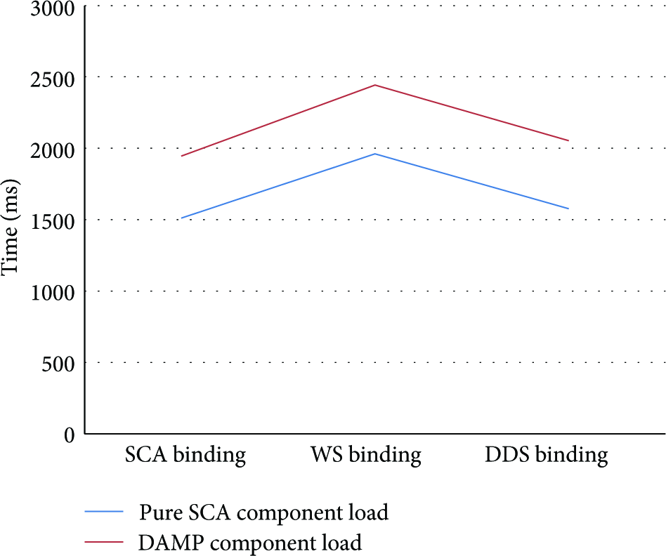
Figure10 shows the component process load times for different SCA bindings. The measured times include the load of the Tuscany SCA Java runtime itself, which consumes most of the time in the instantiation phase. As it can be seen, the developed DDS binding (RTI distribution) is much more efficient than the Tuscany native web services binding, in terms of component instantiation time.

Component load time for different available bindings.
Figure11 shows the operation invocation times (in microseconds) for applications composed of different number of components (one, five, and ten components). The operations considered here are those managed by the middleware manager (init, start, stop, and kill operations). It should be noted that the operations are invoked point to point (unicast) for client server paradigm based bindings, as web services or REST. Thus, the invocation time for the whole application increases almost linearly with the number of components. Conversely, the graph shows the great advantage provided by the publish-subscribe paradigm when the number of components increases. This is represented by the DDS binding when configured in multicast mode.
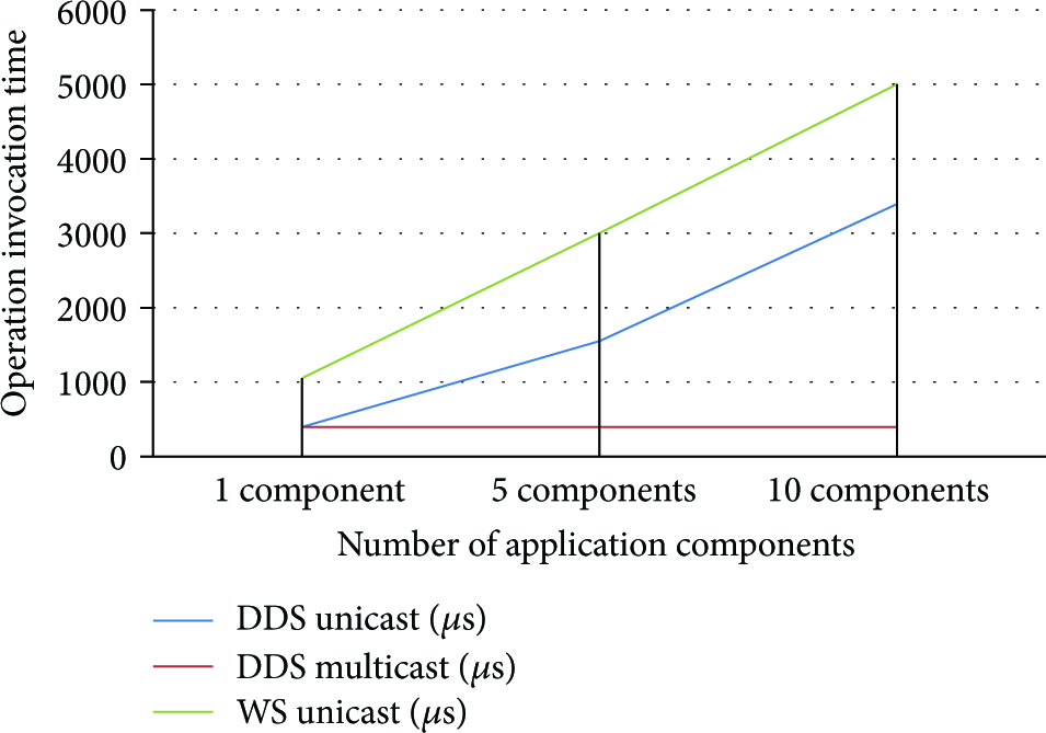
Application response times for different number of components and different bindings.
The influence of the state size in a stateful component initialization is depicted in Figure12. In this case, a component is initialized by the middleware manager with different state size. The influence of the state is almost linear. The response time has been measured in the middleware manager for different state sizes transferred over a DDS binding.
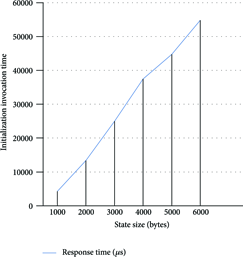
Influence of the state size in a stateful component initialization.
Finally, Figure13 shows the overhead of converting a pure SCA component into a DAMP “compliant” component, depending on the specific binding support.
Cost of DAMP support versus pure SCA.
More specifically, the figures measure the instantiation time of a component running over classical SCA Tuscany versus a component with complete DAMP support. The overtime is due to the instantiation of the control ports (both services and references) that every DAMP component includes. This fee is amply compensated by the extra features that the DAMP platform provides, namely, dynamic system reconfiguration support, QoS and resource management, and fault tolerance.
8. Conclusions and Future Work
This paper proposes a middleware solution that addresses several key needs of distributed systems composed of dynamically reconfigurable component based stateful applications. Such kind of systems share common characteristics with the so-called sensor web systems or IoT, where aspects as dynamicity, heterogeneity, or resource management are key issues and must be properly managed.
The proposed platform builds on top of a general purpose component model (SCA) and provides several services to the system operator and the running applications, which ease the system deployment phase and enable the automatic system reconfiguration in face of external (application unaware) as well as internal (application driven) reconfiguration triggers.
The proposed QoS aware reconfiguration algorithm allocates the system resources to the applications depending on their QoS demand and priority (criticality), and the proposed fault tolerance mechanisms enable stateful recovery in face of component or node crash, thus increasing the availability and dependability of the system.
The platform suitability for an automated warehouse supervision system has been qualitatively validated. The warehouse is composed of tens of hardware nodes that allocated hundreds of software components. The main features of the platform have been validated context of the case study: (1) registration service, (2) execution service, (3) monitoring service, and (4) QoS configuration service.
Also, quantitative analysis of the scalability capabilities of the DAMP middleware has been performed, including numerical analysis of application stateful initialization, depending on the number of components and state size
Future work includes quantitative analysis of composition algorithm execution times, in order to calculate a suboptimal reconfiguration solution in bounded time.
Footnotes
Competing Interests
The authors declare that there are no competing interests regarding the publication of this paper.
Acknowledgments
This work was financed in part by the University of the Basque Country (UPV/EHU) under Project UFI 11/28 and by the MCYT&FEDER under Project DPI2015-68602-R.