
Abstract
Underwater acoustic local area networks (UA-LANs) can be used to improve the coverage of an underwater network by introducing a tier of local area communications. Media access control (MAC) is a crucial issue for UA-LANs. Existing MAC protocols for terrestrial WLANs cannot be directly applied to UA-LANs due to the acoustic channel features of limited bandwidth and high and variable propagation delay. In this paper, we propose a handshake based ordered scheduling MAC (HOSM) protocol for UA-LANs. The nodes with data packets to be transmitted first reserve the channel in a channel reservation phase. Then an order list is calculated, and the data packets of these nodes are transmitted according to this order list. We develop a control packets transmission adjustment mechanism to reduce collisions of control packets. The key idea of this mechanism is to utilize the information of propagation delay to adjust the time instant of control packets transmitting. To improve channel utilization, we present a variant Max-Min Ant System algorithm to calculate an optimal order for each data transmission round. Simulation results have confirmed that the proposed protocol can achieve high throughput with low delay and good spatial fairness.
1. Introduction
With the development of underwater acoustic technology, underwater acoustic sensor networks (UASNs) which utilize sound waves to transmit data are of increasing concern recently to both academia and industry. They can be widely used in ocean environmental monitoring, oceanographic data collection, disaster early warning, and recovery [1–3].
IEEE 802.11 WLAN [4] is one of the most deployed wireless networks all over the world, and it is playing a major role in next generation wireless communication. For underwater environment, underwater acoustic local area networks (UA-LANs) like WiFi networks can be used to provide an additional tier of local area communications which can be complementary to wide-area communications [5]. On the one hand, combined with wired underwater networks, UA-LANs can be utilized to provide wireless access services for underwater sensors and underwater autonomous nodes. On the other hand, when a UA-LAN is compatible with a wide-area underwater acoustic network, it can improve the coverage of the network. Therefore, UA-LANs not only have great research significance but also have a huge application foreground.
Media access control (MAC) is a crucial issue for UA-LANs. It is also a challenging task. One of the reasons is the acoustic channel features of limited bandwidth, high and variable propagation delay, and time-variability. Firstly, the available bandwidth of the acoustic channel is low and variable. The amount of available bandwidth depends on the communication range; a long-range system that operates over several tens of kilometers may have a bandwidth of only a few kilohertz, while a short-range system operating over several tens of meters may have more than a hundred kilohertz of bandwidth [1]. The low available bandwidth would lead to low data transmission rate. Secondly, as the propagation speed of sound is approximately 1500 m/s, the propagation delay of underwater acoustic communication is significant. Moreover, the propagation delay is variable because the propagation speed of sound depends on many factors including temperature, depth, and salinity [6]. Due to the high and variable propagation delay, precise synchronization is difficult to be realized in underwater environment. Thus the MAC protocols relying on precise synchronization are usually difficult to be applied in practical underwater networks. Thirdly, the acoustic channel is time varying. There are two sources of the channel's time variability: one is the inherent changes in the propagation medium and the other is changes caused by the transmitter/receiver motion [6]. The time variability should be paid attention to in the MAC protocol design process. The application requirements of UA-LANs are other reasons that make it hard to design a capable MAC protocol. On the one hand, a UA-LAN is usually requested to provide high and fair rates for underwater nodes. Thus its MAC protocol should have high channel utilization and good spatial fairness, both of which are difficult to be realized in underwater communication due to the high and variable propagation delay. On the other hand, the mobility of nodes is different in UA-LANs. Except for static nodes, some mobile nodes such as underwater robots and autonomous underwater vehicles (AUVs) are usually used to execute special task. Therefore, the MAC protocol should be suitable for the network with mobile nodes.
For terrestrial WLANs, frequency division multiple access (FDMA), time division multiple access (TDMA), code division multiple access (CDMA), and carrier sense multiple access (CSMA) are four main MAC solutions. Nevertheless, none of them can be directly applied to UA-LANs. Narrow available bandwidth makes frequency division impractical. TDMA could also be difficult to be applied to UA-LANs because of the absence of precise synchronization. The high and variable propagation delay makes it expensive to exchange Request-To-Send (RTS) and Clear-To-Send (CTS) packets before each data packets transmission, leading to the inefficiency of CSMA in underwater communication. The near-far problem [7] is usually difficult to be eradicated in the time-varying acoustic channel. This leads CDMA to be not suitable for UA-LANs. There are several existing MAC protocols for UWSNs. But they also would suffer from some problems when they are directly applied to UA-LANs. For example, some of them require precise synchronization. Some others suffer from low channel utilization or spatial unfairness. The rest cannot be suitable for the network with mobile nodes.
Aiming at the above problem, we propose a handshake based ordered scheduling MAC (HOSM) protocol for UA-LANs. This protocol can achieve high channel utilization and good spatial fairness by combining channel reservation with ordered scheduling. Multiple nodes are allowed to reserve the channel in each channel reservation phase. The channel reservation overhead is thus reduced dramatically. A control packets transmission adjustment mechanism is developed to reduce collisions of control packets. The key idea of this mechanism is to utilize the information of propagation delay to adjust the time instant of control packets transmitting. The impact of nodes mobility is considered in this mechanism. As nodes can wait much less time than the maximum propagation for their transmissions by using the ordered scheduling, the channel utilization can be improved. We present a variant Max-Min Ant System algorithm to calculate an optimal order for each data transmission round. The channel utilization can be further improved by this algorithm. Because both the channel reservation and the ordered scheduling do not depend on precise synchronization, precise synchronization is not necessary in this protocol.
The remainder of this paper is structured as follows. Section 2 briefly reviews some related work. Section 3 presents the HOSM protocol. And an approximate throughput analytical model for HOSM is presented in Section 4. In Section 5, the performance of HOSM is evaluated and compared with some typical MAC protocols. Conclusion is made in Section 6.
2. Related Work
There are several existing MAC protocols for underwater acoustic sensor networks. UW-MAC [8] is a CDMA based scheme. It jointly set the optimal transmit power and code length by using a novel closed-loop distributed algorithm. Hybrid TDMA [9] divides time into scheduled and unscheduled access periods to adapt to the changing traffic. Scheduled periods guarantee a certain data rate available to each node, and unscheduled periods provide additional access chance for the nodes with higher data traffic. In [10], Hsu et al. aimed at the scheduling problem caused by spatial-temporal uncertainty and proposed the spatial-temporal MAC (ST-MAC) scheduling based on TDMA. ST-MAC uses spatial-temporal conflict graph and vertex coloring methods to solve the problem of the spatial-temporal uncertainty. In [11], Hsu et al. further proposed two TDMA based heuristic approaches: the traffic-based one-step trial approach (TOTA) and the distributed traffic-based one-step trial approach (DTOTA). TOTA is proposed to solve the coloring problem in a centralized fashion and DTOTA is used to assign the data schedule for tree-based routing structures in a distributed manner. Ordered CSMA [12] combines the concepts of round-robin scheduling and CSMA. Each station transmits immediately after the data packet transmission of previous station with fixed order. By this manner, ordered CSMA can achieve higher channel utilization than TDMA. Fan et al. improved ordered CSMA in [13], and a new protocol called hybrid reservation-based MAC (HRMAC) has been proposed. In HRMAC protocol, the nodes first reserve the channel before transmitting their data packets in a given order.
Molins and Stojanovic proposed a protocol called slotted FAMA [14]. It uses a 4-way handshake with time-slotting to avoid data collisions. To reduce handshake duration, DACAP [15] protocol allows a node to use different handshake lengths for different receivers. The concept of packet train has been first proposed for terrestrial wireless networks in [16]. Inspired by packet train concept and the idea of “receiver-initiated reservations,” Chirdchoo et al. [17] proposed the “Receiver-Initiated Packet Train” (RIPT) protocol, in which multiple nodes are allowed to transmit data packets to a single receiver within each round of handshake. The spatial fairness is a challenging problem in UASNs. Liao and Huang proposed the SF-MAC protocol to solve this problem [18]. The receiver collects RTS packets from all the contenders during a RTS contention period and then determines a contender that has sent its RTS packet earliest by estimating the earliest sending probability of each node. The efficient handshaking mechanism (EHM) [19] is proposed to solve the hidden terminal and spatially unfair problem. It can improve channel utilization by allowing a node to receive packets from multiple potential senders simultaneously. In [20], the bidirectional-concurrent MAC with packet bursting (BiC-MAC) is proposed. It can improve data transmission efficiency by concurrent, bidirectional data packet exchange.
To some extent, these protocols are capable of achieving their performance goals in the network model that they are concerned with. However, they would suffer from some drawbacks in UA-LANs. For the CDMA based schemes, such as UW-MAC, it is usually difficult to eradicate the near-far problem in underwater environment, especially when there exist mobile nodes in the network. For the TDMA based protocols and the time-slotted based protocols, precise synchronization is obligatory. And, for these protocols that aim to solve the problem of spatial unfairness, the fair transmission is usually realized at the expense of channel utilization. For RIPT protocol and BiC-MAC protocol, their performance would decline in UA-LANs due to the impact of nodes mobility. Ordered CSMA protocol can achieve high channel utilization. However, there are some drawbacks in this protocol. Firstly, every node needs to listen to the channel continuously. This would lead to waste of energy. Secondly, when it is applied to the networks with mobile nodes, the information about network topology is needed to be updated frequently. This would lead to the performance reduction. Thirdly, all the nodes must be connected to each other. This requires high connectivity, which is usually impractical for many applications. Although HRMAC has been improved by introducing a channel reservation mechanism, its data transmission is not optimal because it does not provide an optimal order for each round of data transmission. In this paper, we aim at the problems caused by the acoustic channel features and the application requirements of UA-LANs and propose a handshake based ordered scheduling MAC protocol for UA-LANs. It can achieve high channel utilization and good spatial fairness. Precise time synchronization is not necessary, and the impact of nodes mobility is also considered.
3. The Handshake Based Ordered Scheduling MAC Protocol
3.1. Network Architecture
The network architectures adopted in this work are shown in Figure 1. There are two different UA-LAN architectures shown in Figures 1(a) and 1(b), respectively. In Figure 1(a), the packets from UA-LANs are transmitted to the onshore control center by a surface gateway which is equipped with both radio-frequency and acoustic modems, while the UA-LANs shown in Figure 1(b) are connected to the onshore control center through submarine optical fiber cables. In each UA-LAN, there are underwater access points (U-APs) and several static underwater nodes and a small amount of AUVs. The U-AP which is responsible for providing wireless access services for the nodes can be mounted on a surface buoy or the bottom, deployed at the center of the UA-LAN. The static nodes are randomly deployed in the UA-LAN. The AUVs can move into the UA-LAN, equipped with a navigation system. The radius of a UA-LAN is the maximum communication range of the U-AP. All the nodes of a UA-LAN can communicate with the U-AP by acoustic channel. There are two layers of acoustic communication in the network shown in Figure 1(a). U-APs and the surface gateway constitute the first layer. Nodes (including static nodes and mobile AUVs) and U-APs constitute the second layer. As the distance between U-APs and the surface gateway is usually longer than that between nodes and U-APs, the first layer is allocated at a lower operating frequency than the second layer, and the frequency of these two layers is orthogonal so that they will not create interference for each other. Our protocol is designed to be used in each UA-LAN shown in Figure 1.
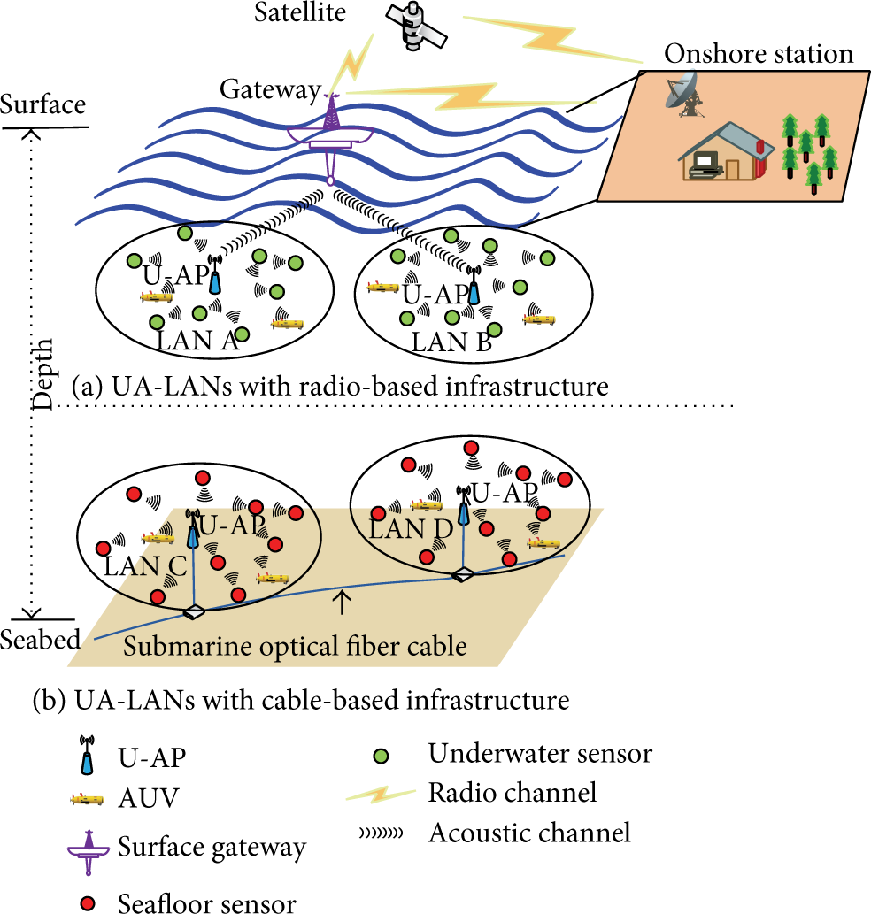
Underwater acoustic local area networks.
3.2. How the HOSM Protocol Works
In each UA-LAN, the U-AP is selected as the coordinator node, which is responsible for providing wireless access services for the nodes and controlling the data transmission of the network. As propagation delay can be obtained in the network initialization stage by comparing the timestamp on control packets with a local clock, we assume that the coordinator can know the propagation delay between any two static nodes, and each static node can know the propagation delay between the coordinator and itself. Although this procedure requires synchronization, the synchronization can easily be realized because the initialization stage is short, and clock drift can be negligible if the synchronization is carried out right before deployment [17]. An AUV can also know the propagation delay between the coordinator and itself owing to its navigation system.
We divide the data transmission process of HOSM into a channel reservation phase and a data transmission phase. In the channel reservation phase, a Start-To-Reserve (STR) packet is first broadcasted by the coordinator to inform all of the nodes that they can start to reserve the channel. After receiving the STR packet, the nodes with data packets to be transmitted should send a Request-To-Send (RTS) packet to the coordinator. Then the coordinator will calculate a data transmission order list for these nodes and inform these nodes of their orders by broadcasting an ORDER packet. In the data transmission phase, the nodes extract the data packets transmission order list once receiving the ORDER packet; then they will transmit data packets according to their orders. Each node transmits immediately after sensing the end of the carrier from its previous node. In Notations section, we show the notations used for the HOSM protocol, and Figure 2 shows an example of how the data transmission process is carried out.

An example of the data transmission process of HOSM.
3.2.1. Channel Reservation Phase
Multiple nodes are allowed to reserve the channel in a channel reservation phase. This would lead to collisions of control packets. To reduce the probability of control packet collisions, we propose a control packets transmission adjustment mechanism that utilizes the information of propagation delay to adjust the time instant of control packets transmitting. Each node's control packets transmissions are controlled by a control packets transmission order
In the channel reservation phase, the coordinator first calculates the control packets transmission orders of all the static nodes according to the propagation delay between the coordinator and static nodes. Then it broadcasts a STR packet which contains the control packets transmission orders list of static nodes. After receiving the STR packet, static nodes will extract their orders, and mobile nodes will determine their orders themselves according to the orders list of static nodes and the propagation delay between the coordinator and themselves (the procedure can be seen in Section 3.3). Once obtaining an order, a node with data to be transmitted will calculate the time instant

After the STR packet was transmitted, the coordinator should wait for a period of

After the coordinator waits for a period of
3.2.2. Data Transmission Phase
In the data transmission phase, the nodes transmit their data packets according to their data packets transmission orders. After sending a RTS packet, a node will listen to the channel and wait to receive an ORDER packet. Once receiving an ORDER packet, the node extracts the data packets transmission order list. The node whose order is the first order will transmit data packets immediately after a hardware transmit-to-receive transition time. Other nodes will continue to listen to the channel. When a node senses the end of the carrier from its previous node, it starts to transmit its data packets immediately. This ordered scheduling mechanism makes nodes wait much less time than the maximum propagation for their transmission and thus can improve channel utilization. An example is shown in Figure 3. There are eight nodes (nodes A, B, C, D, E, F, G, and H) in the network. In the current data transmission round, three nodes, A, B, and C, have reserved the channel. And the current data transmission order is C, A, B. Therefore, node C will send its data packets once receiving the ORDER packet. Node A will start to transmit its data packets after sensing the end of the carrier from node C. Similarly, node B will start to transmit its data packets after sensing the end of the carrier from node A.

An example of the data transmission phase.
In order to know the finish time of a data transmission round, the coordinator should listen to the channel after transmitting an ORDER packet. When the coordinator senses the end of the carrier from the last node, it means this data transmission round has been completed. The coordinator begins the next data transmission round.
Because the data transmission of a node is triggered by a right data packet from its previous node (except for the first node), a consequence is that the protocol may be failure caused by a transmission exception. To solve this problem, a timer should be set by the coordinator after it sent an ORDER packet; the time is set to be

Actually,
3.3. The Transmission Order Calculation of Control Packets
As mentioned earlier, each node's control packets transmissions are controlled by a control packets transmission order. An example of transmission order calculation of control packets is shown in Figure 4.

An example of transmission order calculation of control packets.
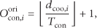
The coordinator first calculates the original control packets transmission orders of all the static nodes as follows:

Using the above method, the control packets transmission orders of static nodes can be calculated by the coordinator. However, the order of a mobile node calculated by the coordinator is usually not accurate, because the propagation delay between the coordinator and the mobile node will change. Considering that, a mobile node can know the propagation delay between the coordinator and itself owing to its navigation system. Therefore, it can determine its order itself. For example, mobile node m first calculates its original order
Seemingly, using this mechanism to calculate the control packets transmission order will increase overhead, because the duration of channel reservation may expand as caused by the adjustment process. Actually, although this case could happen when the network is very dense or a large number of nodes are deployed at the boundary of the network, the additional overhead is insignificant compared with the propagation delay, because the interval
3.4. The Transmission Order Calculation of Data Packets
To maximize the efficiency of the network, an optimal data packets transmission order list should be built by the coordinator for each data transmission round, where the optimal order list is an order list that can minimize the total propagation delay among nodes. Therefore, our goal is to find out a tour that starts from the coordinator and goes back to the coordinator after visiting each of the other nodes exactly once, and the total length of this tour is minimum. We take the network topology shown in Figure 5(a) for instance. Two cases should be considered. The first case is the fully connected network, which can be modeled as a complete graph shown in Figure 5(b). In this network, there always exists a direct path between two nodes. The other case is the partially connected network, which can be modeled as a connected graph shown in Figure 5(c). In a partially connected network, the communication range of a node is limited, and there could not always exist a direct path between any two nodes, but there always exists a path between two nodes because all the nodes can communicate with the coordinator.
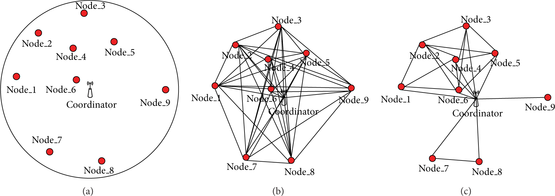
A network topology for transmission order calculation of data packets.
3.4.1. Fully Connected Network
Suppose the number of nodes that have reserved channel successfully is n, and the propagation delay between node i and node
Obviously, the attempt to find a tour (a data transmission order list) that can minimize the total length
3.4.2. Partially Connected Network
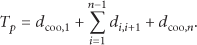
In a fully connected network, the coordinator is visited only twice (the start point and the end point) by an optimal tour. However, for a partially connected network, we cannot always find a tour that only visits the coordinator twice and each of the other nodes exactly once. This is because the network may be constituted by several disconnected subnets if the coordinator is removed. And there is no path that can connect all the subnets. Considering that, the coordinator can communicate with all the other nodes. We can utilize the coordinator to connect these subnets. Based on this idea, to build an optimal data transmission order list in such network can be modeled as the following problem: to find a tour that starts from the coordinator and goes back to the coordinator after visiting each of the other nodes exactly once, and the coordinator can be visited more than twice in this tour; besides, the total length of this tour is minimum. The total length of the tour can be expressed as follows:

The above problem is no longer a classical TSP. To work out this problem, we present a variant Max-Min Ant System algorithm described in Algorithm 1. Compared with the original MMAS algorithm [22], the improvement of the variant MMAS algorithm is that when an ant cannot find any feasible node to move into from the current node, it will go back to the coordinator and travel to the remaining nodes from the coordinator. Here, a feasible node is a node that can communicate with the current node and has not been visited.
(1) initialize parameters (2) set termination condition (e.g., number of iterations) (3) obtain an initial best solution by using the greedy algorithm (4) set (5) set (6)
(1) for each ant k do (a) start from the coordinator, (b) if there is no feasible node to move into go back to the coordinator else calculate the transition probability of all the feasible nodes as follow: then, choose in probability the next node j to move into; (c) if all the nodes are in the current (2) choose the shortest path as the BestPath.
(1) use the BestPath to update the trails as follows: (2) calculate if if (3)
if match the termination condition, output the best solution. otherwise, go to
In the initialization phase of Algorithm 1, we use the greedy algorithm to obtain an initial best solution and then calculate the maximum pheromone trail
An order list calculated by employing Algorithm 1 could include the coordinator. In this case, the coordinator should sense the carrier from its previous node and transmit a short token packet to the following node after its previous node finishing data transmission. The following node should start to transmit data packets once receiving this token packet.
4. Throughput Analysis
We assume that there are N nodes in our analytical model, and the arrivals of each node's packets follow a Poisson distribution with average

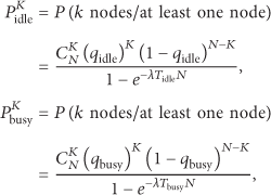
We define two states, the idle state and the busy state, for a data transmission round. The state of a data transmission round is idle when no node wants to transmit data. Otherwise, its state is busy. Whether a node has packets to be transmitted in a data transmission round or not depends on the duration of the previous data transmission round. Suppose

Similarly, when the previous data transmission round is in busy state, this probability can be expressed as

For any data transmission round, its state only depends on the state of the previous data transmission round. Let
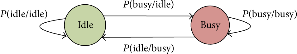
Markov chain model for state of a data transmission round.
Obviously, in any data transmission round, the number of nodes with data to be transmitted obeys binomial distribution

According to (11), the steady-state probability matrix of

It is important to determine the expected number

According to (14), we can calculate the parameter

In the HOSM protocol, when a data transmission round is in idle state, its duration is the duration of the channel reservation phase. Therefore,

And when a data transmission round is in busy state, its duration is the duration of the channel reservation phase plus the data transmission phase. Therefore,

Obviously, the mean duration of the total data transmitted in the busy period is


Similarly, the expected duration of an idle period is multiplying the duration

Therefore, the throughput of the HOSM protocol can be expressed as

From (21), we can find that the throughput of HOCM is determined by
5. Simulation Results and Analysis
To evaluate the performance of the proposed protocol, we carry out several simulations under different offered load or different number of nodes. The protocol is compared with TDMA and slotted FAMA. TDMA is a schedule based MAC protocol, and slotted FAMA is a contention based MAC protocol.
We carry out these simulations in the OPNET simulator. Several nodes are randomly deployed in a circular area with the radius of 1 km. A coordinator is deployed at the center of the circular area. All the nodes are equipped with a half-duplex, omnidirectional transceiver. The nodes' transmission range is 1 km. For convenience, we assume that the sink node of all the packets is the coordinator. The average transmitting and receiving power of the acoustic transceiver are set to be 10 Watt and 2 Watt. The listening power is 0.08 Watt. In the HOSM protocol, the nodes will go to sleep when they finish transmitting data packets and be awoken until new data packets arrived. The sleeping power is set to be 0 Watt. We assume that the traffic load is divided evenly among all the nodes according to the Poisson distribution, and each node has an infinite send queue. Each node sends no more than one packet in each data transmission round. Each data packet is 4000 bits long. Each control packet is 100 bits long. The bit rate is 10 kbps. The acoustic propagation speed is assumed to be 1500 m/s. The channel is assumed to be error-free so that all packet losses are purely due to the MAC protocol's performance. We do not implement ACK for any of the protocols simulated; thus there is no retransmission for lost packets.
The performance of the HOSM protocol is evaluated in terms of network throughput, average delay, energy consumption, and spatial fairness. The variables are offered load and number of nodes. Here, definitions of “throughput” and “offered load of network” are given by [24] as follows:

The definition of “offered load per node” is given as follows:

5.1. Simulation Results in Static Networks
We first evaluate the performance of the HOSM protocol in static networks. In this simulation scenario, all the nodes are stationary once deployed.
5.1.1. Throughput
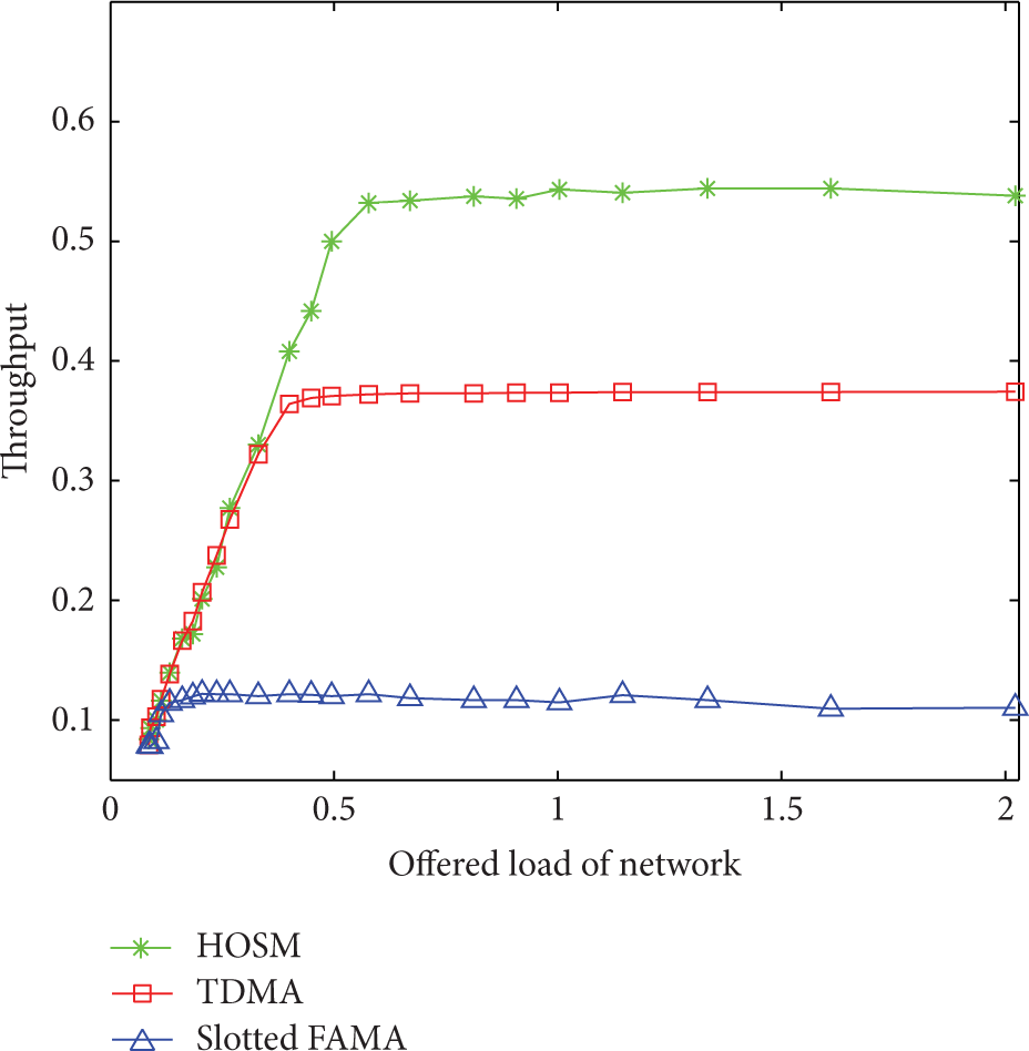
As shown from Figure 7, in the saturation throughput region, HOSM outperforms TDMA and slotted FAMA by around 47% and 360%, respectively. It means that although it used the handshake based channel reservation mechanism, the HOSM has higher channel utilization than TDMA. This is because the ordered scheduling is more efficient than the slot time based scheduling used in TDMA. The simulation result also proves that slotted FAMA is inefficient in underwater environment, because it only transmits a single data packet after per-round handshake, which suffers from underutilization of the channel when the propagation delay is high. However, our channel reservation mechanism allows multiple nodes to transmit data packets after per-round of channel reservation and can reduce the total channel reservation overhead greatly and thus can improve channel utilization. It also can be seen that the throughput of HOSM in theoretical analysis is close to the throughput in simulation. The difference between these two results is because our theoretical analytical model is an approximate analytical model based on the Markovian chain; thus its result is also an approximate result.

Throughput with offered load of network for number of nodes,
From Figure 8, we can see that the saturation throughput of HOSM increases with the increasing of number of nodes, as the time interval of data transmission depends on the propagation delay between two nodes. With the increasing of the number of nodes, the average propagation delay between two nodes will reduce. So the saturation throughput can be increased. As seen from Figure 8, the saturation throughput of HOSM protocol is less than that of TDMA when the number of nodes is less than 6. This is because the distance between two nodes is very large when the network is sparse, leading to low efficiency for ordered scheduling. And, in this case, the channel reservation overhead would lead the saturation throughput of HOSM to be less than that of TDMA.
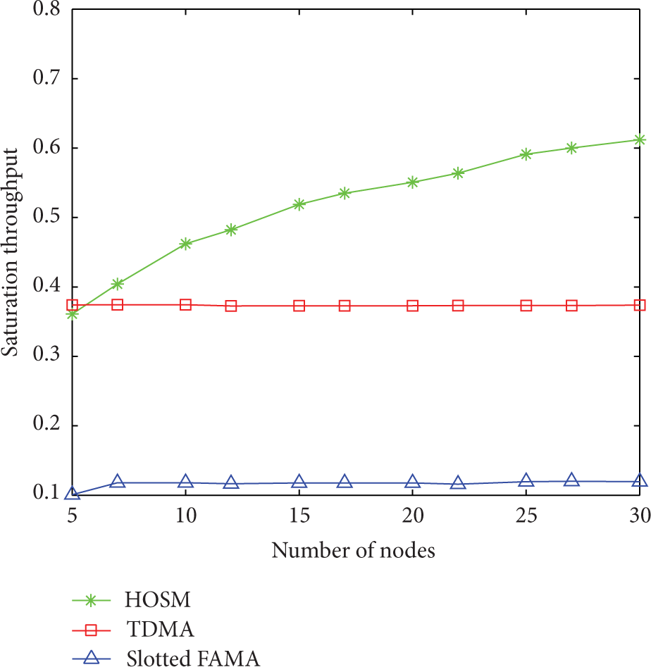
Saturation throughput with number of nodes.
Notice that the high performance of TDMA and slotted FAMA is achieved under the condition of precise synchronization. And the clock drift will damage the performance of these two protocols seriously. However, the precise synchronization is not necessary anymore in our HOSM protocol.
5.1.2. Average Delay
The average delay is defined as the average duration of a data packet from arriving at a sender to being received by a receiver successfully. Figure 9 shows the average delay performance of these three schemes. It can be seen that the HOSM significantly outperforms TDMA and slotted FAMA. This is because HOSM is more efficient than TDMA. On the one hand, only the nodes with packets to be transmitted will occupy channel resource in HOSM owing to its channel reservation mechanism, but, in TDMA, every node will obtain a slot time no matter whether it needs to send data or not. On the other hand, the ordered scheduling is more efficient than the slot time based scheduling used in TDMA. For slotted FAMA, the nodes need to wait for a long period for channel contention before transmitting a data packet, leading to long delay. It can also be seen from Figure 9 that the average delay of TDMA and HOSM increases dramatically after the offered load reaching a respective threshold. The thresholds of TDMA and HOSM are 0.27 and 0.57, respectively. That is because the network reaches saturation when the offered load is higher than the threshold, so packets will accumulate in the send queue constantly, leading to dramatic increase in the average delay.
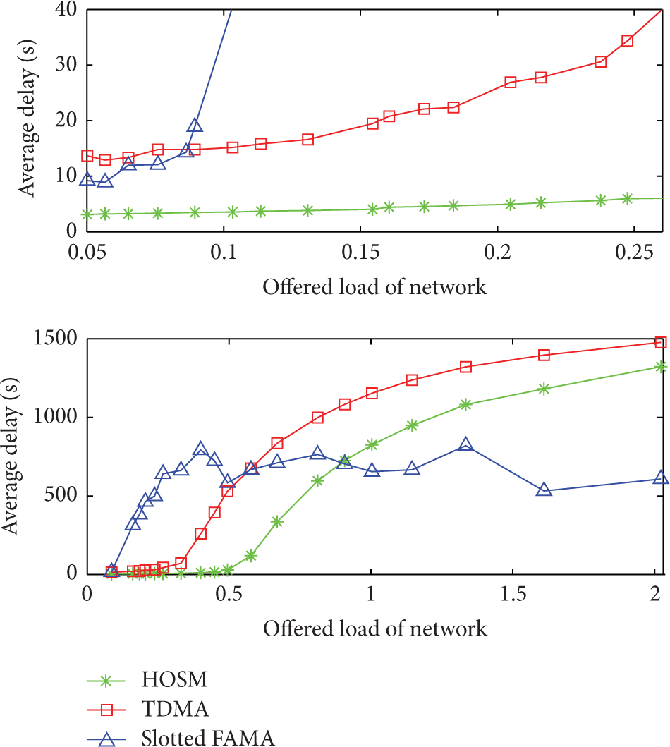
Average delay with offered load of network for number of nodes,
It can be seen that the average delay of slotted FAMA fluctuates strongly in Figure 9. When the offered load is low, its average delay is much larger than that of the other two protocols, but when the offered load is high, it becomes less than that of the other two protocols. Actually, this phenomenon is caused by the unfairness of slotted FAMA, which will be discussed in the following section.
Figure 10 shows the average delay performance for different number of nodes. It can be seen that the influence of the number of nodes for HOSM is much smaller than that for TDMA and slotted FAMA. The reason is that only a fraction of new nodes with data to be transmitted will affect the delay in HOSM, while all the new nodes will occupy slot times and affect the delay in TDMA. And, for slotted FAMA, the more the nodes, the greater the competition, so its delay increases sharply.

Average delay with number of nodes for offered load per node to 0.01.
5.1.3. Fairness
Fairness that implies equal allocation of resources is an important factor to be considered in wireless communication performance evaluation. The definition of “fairness index” is given by [25] as follows:

From Figure 11, we can see that the fairness indexes of HOSM and TDAM are approximately equal to 1. It means that these two protocols can realize fair transmission in static networks. For slotted FAMA, as shown from Figure 11, its fairness index decreases with the increasing of the offered load. This means that slotted FAMA is unfair to the nodes at slightly high load, and the higher the load, the more the unfairness. This is because the RTS packets from the nodes that are closer to the receiver can be earlier received. These nodes thus have more chances to access the channel. When these nodes have high load, they will occupy the channel in a long period, leading to be unfair to the farther nodes. It is the unfairness that leads the average delay of slotted FAMA to be very unusual in Figure 9. When the offered load is high, most of the received packets are from the nodes that are closer to the receiver. And because the channel is occupied by a small number of nodes, their packets will wait for a shorter time in the send queue. Therefore, the delay of slotted FAMA is lower than that of the other two protocols under high offered load.
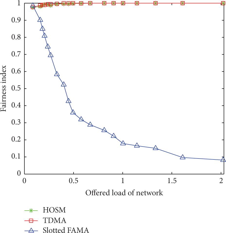
Fairness index with offered load of network for number of nodes,
5.1.4. Energy Consumption
Figure 12 shows the energy consumption per node of these three protocols. It can be seen that the coordinator of HOSM has the maximum energy consumption. That is because the coordinator must listen to the channel continuously and control the data transmission of the network, and both processes will consume a lot of energy. Figure 12 also shows that a node of HOSM consumes more energy than a node of TDMA, and slotted FAMA consumes the least energy. This is because the node of HOSM can transmit more packets than the node of TDMA during the same amount of time, and slotted FAMA transmits the least packets. Figure 13 shows the energy efficiency of these three protocols, where the energy efficiency is defined as the energy consumption per packet. It can be seen that the energy efficiency of slotted FAMA is minimum, and the energy efficiency of HOSM is slightly below that of TDMA. This is because slotted FAMA needs to consume large amounts of energy to contend channel. And HOSM also needs to consume energy to reserve channel before sending data packets. It can also be seen from Figure 13 that the performance of HOSM outperforms that of TDMA when the offered load of network is low (less than 0.6). That is because the nodes of HOSM will go to sleep when they finish transmitting data packets, but we have not implemented any sleeping mechanism in TDMA.

Energy consumption per node with offered load of network for number of nodes,

Energy consumption per packet with offered load of network for number of nodes,
5.2. Simulation Results in the Networks with Mobile Nodes
To evaluate the performance of HOSM in the network with mobile nodes, we deploy 18 static nodes and 2 mobile nodes. The mobile nodes move randomly in the simulated area with the speed of 2 m/s, and they are always able to get their location information.
Figures 14 and 15 show the performance of throughput and average delay, respectively. It can be observed that HOSM remains useful in the network with mobile nodes, and it still outperforms TDMA and slotted FAMA in terms of network throughput and average delay. Figure 16 shows the fairness index of these three protocols. Compared with Figure 11, the fairness index of HOSM drops slightly. It means that the mobile nodes have slight damage on the fairness of HOSM. This is because the algorithm introduced in Section 3.3 is based on an assumption that static node has priority. A mobile node must ensure that its RTS packet will not conflict with any RTS packets from static nodes before sending the RTS packet; otherwise, it will not send the RTS packet. Therefore, it is not absolutely fair to the mobile node. However, this assumption is reasonable, because a mobile node could have more storage space and more energy supply, and its mobility could make it obtain a chance of data transmission when it moves to another location.
Throughput performance in the network with mobile nodes.

Average delay performance in the network with mobile nodes.
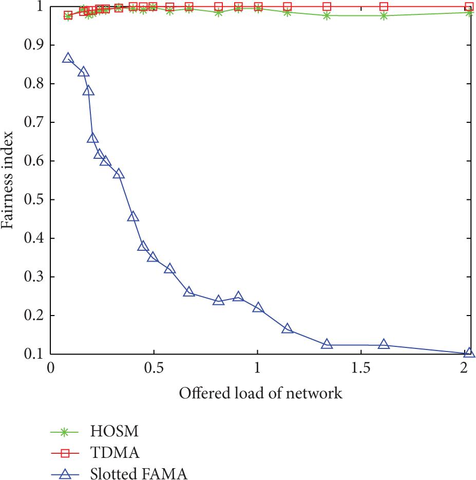
Fairness index in the network with mobile nodes.
6. Conclusion
The acoustic channel is characterized by limited bandwidth, high and variable propagation delay, and time-variability. A UA-LAN is usually requested to provide high and fair rates for the nodes with different mobility. Due to these acoustic channel features and application requirements of UA-LANs, the existing MAC protocols cannot be directly applied to UA-LANs. In this paper, we propose a handshake based ordered scheduling MAC (HOSM) protocol for UA-LANs. The contributions of this paper are summarized as follows. (a) We propose the HOSM protocol for UA-LANs. It can achieve high channel utilization and good spatial fairness by combining channel reservation with ordered scheduling. Precise time synchronization is not necessary, and the impact of nodes mobility is considered in this protocol. (b) A control packets transmission adjustment mechanism is developed to reduce collisions of control packets. The key idea is to utilize the information of propagation delay to adjust the time instant of control packets transmitting. To improve channel utilization, we come up with a variant Max-Min Ant System algorithm to calculate an optimal data packets transmission order for each data transmission round. (c) We present an approximate throughput analytical model based on the Markovian chain for HOSM protocol, and an approximate throughput expression is inferred. (d) The performance of the proposed protocol is extensively evaluated via simulations in both static networks and the network with mobile nodes. The simulation results have confirmed that this protocol can achieve high throughput with low delay and good spatial fairness.
In the future, we will expand the proposed protocol with a sleeping mechanism to reduce energy consumption. And a priority mechanism will be introduced to adapt to the traffic with different priorities.
Footnotes
Notations
Conflict of Interests
The authors declare that there is no conflict of interests regarding the publication of this paper.
Acknowledgments
This paper is supported by “National Program on Key Basic Research Project (973 Program) (Grant no. 2011CB707106)” and National High Technology Research and Development Program (863 Program) (Grant no. 2014AA09A512).