
Abstract
The partially stabilized zirconia (PSZ) ceramic has wide applications due to its excellent mechanical toughness and chemically inert and electrical properties for fabricating various devices. In this paper, a novel high temperature pressure sensor with the PSZ was designed and fabricated. The sensor was designed based on the small deflection theory, which enables its theoretic pressure-capacitance capability up to 60 bar. HTCC process technology was used to fabricate the sensor, which would realize a completely passive LC resonant circuit integrated on the ceramic substrate. According to the coupling principle, noncontact testing is achieved using the designed readout system, with average sensitivity up to 38 kHz Bar−1 presented. Compared to the fabrication and measurement of traditional sensors, excellent packaging process is demonstrated, and the sensor can be completely tested from 0 to 60 bar.
1. Introduction
Instantaneous precise measurement pushes the limit of the dynamic testing technology continuously. Until now, the test technology referring to the key parameters under harsh environment is still unreachable [1]; the wireless pressure measurement especially under high temperatures has become increasingly critical in automotive, aerospace, and industrial applications [2–4]. The conventional pressure sensors based on silicon material have been used widely in different occasions. However, they would face great challenges in high temperatures for the intrinsic limits of the material. Other materials, such as silicon nitride and silicon carbide, despite having excellent robustness, are rarely used for standard fabrication because their process is not so mature compared to silicon. Seen as a new-type material, the partially stabilized zirconia ceramic (PSZ) has very high fracture toughness and has one of the most highest maximum service temperatures (0–1850°C) among all of the ceramics. It would also keep mechanical properties when the temperature is close to its melting point (2500°C), which makes great sense for fabrication of pressure-sensitive devices under high temperature.
Noncontact wireless passive telemetric sensing is one of the methods using frequency for continuous and reliable pressure measurements. The sensing methodology requires an external reader to interrogate environment pressure variations electrically registered by an implanted sensor through a wireless inductive coupling link. The concept, shown in Figure 1, was first proved in 1967 using a sensor with resonant circuitry implanted to the anterior chamber of the eye [5], which then was further researched in the development of various pressure microsensors [6–8]. The model enables straightforward pressure sensing by utilizing an implanted sensor that records pressure variations in high-temperature environments, so that the pressure can be directly measured by using an external reader wirelessly interrogating the implant. In the last decades, due to the development of micromachining technology, microelectromechanical system (MEMS) sensors made of silicon are the major devices used in detecting pressure [9]. However, silicon sensors with PN-junctions exhibit a restriction; that is, they cannot be used above 150°C, since the leakage current across the junctions drastically increases above 150°C [10]. In addition, the mechanical properties of silicon will deteriorate as the material becomes easily deformable when pressure is applied above 500°C [11]. Using SOI material can increase the operation temperature of sensor, but sensor becomes invalid because the silicon material will lose elasticity at 500°C [12]. Sensors demonstrated in the literature have certain deficiencies: the Georgia Institute of Technology has designed a wireless high temperature pressure sensor using low temperature cofired ceramic (LTCC) material. However, the sensor is only tested up to 450°C [13–16]. Another team in Novi Sad (Serbia) demonstrated a better structure, but worse performance [17–20]. Recently, Professor Xiong's team has demonstrated a greater sensitivity and a better performance, but the measuring range was not up to 50 bar and the operating temperature was only up to 500°C [21, 22]. However, the coupling distance and performance of the sensors designed before do not operate so efficiently and the pressure tests for these elements have not been taken under composite high-temperature environment.
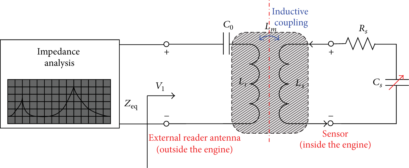
Conceptual schematic of the passive wireless pressure sensing.
These facts seriously hinder its application especially under extraordinary high-temperature environments (>800°C). Thus, we need to further improve the full-scale range and the operating temperature of the sensor.
In this paper, we developed a microfabricated wireless passive pressure sensor with HTCC technology [13] to realize a better applicability and feasibility of the sensor and more stable pressure data in real time under harsh environments such as high-temperature environment. The working principle is described as follows: the external pressure would cause variation of capacitor, so we can obtain the pressure value from the frequency as the LC resonant frequently changes. A readout system is designed to extract the pressure information contained in the sensor's resonant frequency. Different from the previous sensor, a new material is applied for the proposed sensor, and an embedded structure design and fabrication process are studied. Measurement and characterization analysis in high-pressure environment (0–60 bar) are achieved. Featuring zirconia ceramic as the high temperature resistant material, the pressure sensor is designed to be completely implantable in the high-temperature environment so that long-term pressure monitoring inside the engine can be fulfilled.
2. Design
2.1. Principle of Measurement
The concept of the wireless pressure sensing system in the passive electrical sensing scheme is shown in Figure 1; the implanted sensor can record reliable pressure variations using corresponding electrical characteristic changes, which are measured from the external reader through a wireless inductive coupling link. The associated pressure monitoring method as shown in Figure 2 is proposed for continuous monitoring in harsh environments.

Integrated reader antenna and the sensor on the waterproof device in harsh environments.
The sensor implant is designed to have an electrical LC resonant circuit with a corresponding resonant frequency represented as


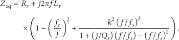

The real part-rise magnitude determines the signal strength in the wireless sensing system and is dependent on k and
In case of high-temperature environment, it is demonstrated that the sensor's Q value which related to the changes of temperature limits the operating temperature at 400°C [13, 14]. The value of mutation point of impedance's real part at peaks changes less obviously as the Q value varies; even the resonant characteristics for extracting the resonant frequency disappear. The real part-rise magnitude of antenna coil from input impedance for the quality factor variation is shown in Figure 3. The main reason is that the relative dielectric constant and loss of inductance coil from ceramic substrate of sensing elements become different as temperature changes. The characteristics disappear when the value of Q reduces, in other word, the coupling energy cost totally at the active power rather than reactive power which beneficial for detecting.

The real part-rise magnitude of antenna coil from input impedance for the quality factor variation.
Another key parameter which affects the extraction of resonance frequency feature is the coupling factor K, which is related to geometry size, coupling distance, and magnetic permeability of inductance coil of antenna and passive sensor ranging from 0 to 1. The impedance magnitude of antenna coil for the coupling coefficients variation is shown in Figure 4. In the actual detection system, the coupling factor K reduces under 0.3 when coupling distance is far away or the size of the inductance coil is very small; the mutual inductance coupling characteristics of the remote sensor cannot be detected at reading antenna (even including the high precision impedance analysis instrument). Therefore, the coupling factor K of readout testing system proposed in this work is chosen at 0.3~1; however the ideal case

The impedance magnitude of antenna coil for the coupling coefficients variation.
2.2. Sensor Circuit Structure Parameters
Figure 5 shows the design of the microsensor comprising a pressure-sensitive parallel-plate variable capacitor embedded in a deformable diaphragm chamber, a spiral metal wire serving as planar inductance, and a flexible ceramic sensitive membrane with electrodes on as the capacitor.

Pressure sensor designing schematics with zirconia ceramic substrate.
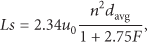
The design particularly features a larger square substrate to incorporate a larger planar spiral inductance. From the engineering aspect, the electrical characteristics of the sensor can be determined by using the established models [22], where the electrical inductance of such a circular spiral coil can be calculated as

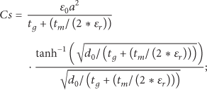
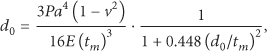
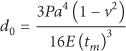
For the case when the deflection is small compared to the plate thickness (
Deduced from the aforementioned description, parameters of the sensor including capacitance plate radius, height of the embedded cavity, and height of the sensitive membrane were designed and the specific parameters of the sensor designed were shown in Table 1.
Parameters of the designed sensor.

2.3. Readout System
In this paper, a readout system is designed to measure the pressure sensor's resonant frequency. Figure 6 demonstrates the major components of the readout system, which include the reader antenna fabricated on printed circuit boards, the pressure sensor inductively coupled to the reader antenna, the readout circuit, and the measurement cable (regular

Major components of the designed readout system.
The readout system is able to measure frequencies between 1 MHz and 100 MHz. The method used to extract the sensor's resonant frequency is based on the changes in the shape of the measured dc output voltage curve. The measured dc output voltage is related to the real part of reader antenna impedance: when the sensor is excited at resonance, the real part of reader antenna impedance changes greatly; then, the readout system can extract the sensor's resonant frequency from the dc output voltage information.
2.4. Sensor Structure Scheme
Similar to devices designed with LTCC (low-temperature cofiring ceramic) material, devices with HTCC (high-temperature cofiring ceramic) material mainly take three essential parts into consideration: formation of a flexible membrane, a sealed cavity, and the integration of an LC resonant circuit. One of the major differences between the previous sensor and the sensor we designed is the introduction of ESL 5570 and PSZ tape 42020, whose parameters are shown in Tables 2 and 3, respectively. ESL 42020 high-temperature PSZ (partially stabilized zirconia tape) tape is a flexible cast film of partially stabilized zirconia (PSZ) powder dispersed in an organic matrix. This material is designed to be sintered in the temperature range of 1450°C–1550°C to yield a dense white-colored ceramic. ESL 42020 tape is provided on a silicone-coated polyester film to protect the tape from mechanical damage and aid in handling. Pt inks (ESL 5570 Series) are used for printing, which can be cofired for use applications such as planar sensors.
Parameters of the ESL 5570.

Parameters of the PSZ tape 42020.

ESL 49000, a flexible cast film of fugitive powder dispersed in an organic matrix, is firstly introduced to generate the sealed cavity. This material is designed to be burned out in the temperature range of 600°C–800°C to yield a void where the tape was placed. ESL 49000 tape is provided on a silicone-coated polyester film to protect the tape from mechanical damage and aid in handling.
In addition, according to the small deflection theory, increase of the thickness of the sensitive membrane and decrease of the sensitive membrane area would both contribute to improvement of the pressure range. Embedded capacitance electrode inside the sensor is designed to increase the capacitance as the distance between capacitor plates is shortened, as shown in Figure 7. Capacitance increases will lead to the decrease of the frequency, to some extent; this is advantageous to signal collection in low frequency range. By the simulation using the ANSYS software, the deflection, stress, and strain of the zirconia ceramic membrane under 60 bar and at 800°C, respectively, are shown in Figure 8.
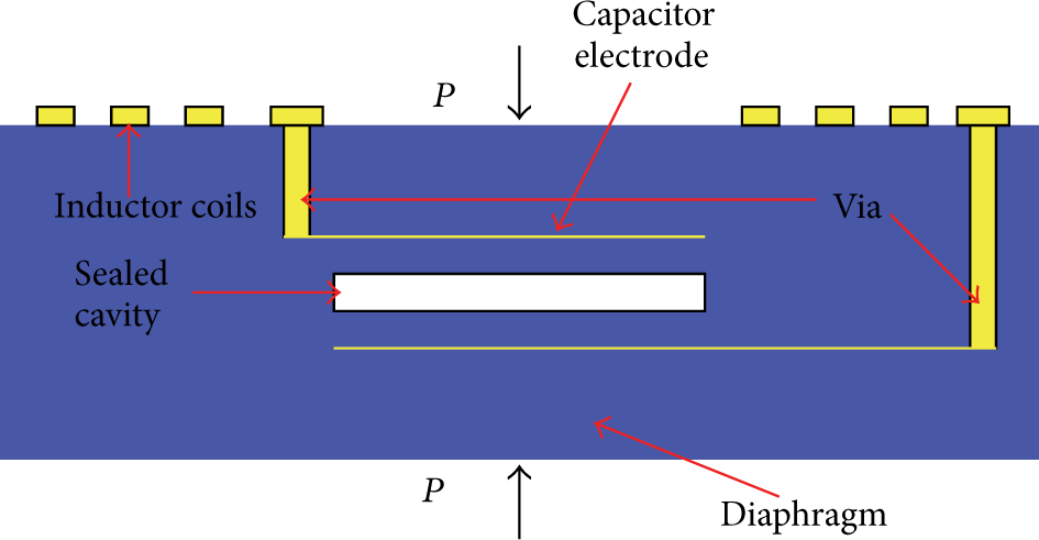
Schematic cross-sectional view of the sensor.

Ansys simulation of the membrane deflection (a), stress (b), and strain (c) load under 60 bar. ANSYS simulation of membrane deflection (d), stress (e), and strain (f) at 800°C.
3. Fabrication
The first step is to cut the green tape using punching machine. The punch file is used to cut accurate cavity, via, and alignment holes, as illustrated in Figure 9, step 1. Detailed schematic layout and geometrical values used for cutting this design are described in Table 1.

Fabrication process for pressure sensor.
To achieve embedded passives series resonance circuit within the substrate, ESL 5570 platinum conductor was screen-printed while the ceramic tape was in a green state, illustrated in Figure 9, step 1. The top planar spiral and electrodes are screen-printed on the first layer, shown in Figure 9, step 1. The wet ink is allowed to dry in an oven at 150°C for 15 minutes prior to lamination. The fifth layer is defined as the cavity. Capacitance electrode plates are printed in the fourth and the seventh layers, respectively. All sheets, except for the last three sheets, have vias on, through which the inductor and capacitor would be connected to form a series resonant circuit; the last two layers are used merely for increase of the sensitive membrane thickness. All layers are assembled to form a ceramic body. ESL 5575 platinum conductor, used to fill the via hole, is then allowed to dry in oven at 170°C for 5 minutes. Assembly of the device begins with laminating the nine layers separately illustrated in Figure 9, step 2, in vacuum condition. The top section is assembled over the bottom and middle sections to form the final stack and then is laminated under pressure of 21 MPa at 80°C, which ensures that areas over the cavity are well laminated before final assembly. The top, middle, and bottom sections are then assembled and laminated, illustrated in Figure 9, step 2. Contact between the top metal spiral and via during lamination is sufficient to ensure the metal melts and create a contact during sintering.
As shown in Figure 9, step 3, the laminated stack is sintered in a box furnace in air for 85 minutes from 430°C to 600°C (2°C·min−1 ramp rate) to bake off the organics; slow heating rate from 600°C to 800°C (3°C min−1 ramp rate) is used to make the fugitive tape volatile and then 120 minutes at 1500°C to form a dense zirconia; then the structure is cooled at 5°C min−1 ramp rate or slower; the specific sintering curve is shown in Figure 10. The microfabricated sensors with sealed cavity and image of inductor coils observed by scanning electron microscope (SEM) are illustrated in Figure 11.
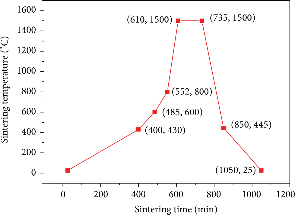
Temperature process control curve.
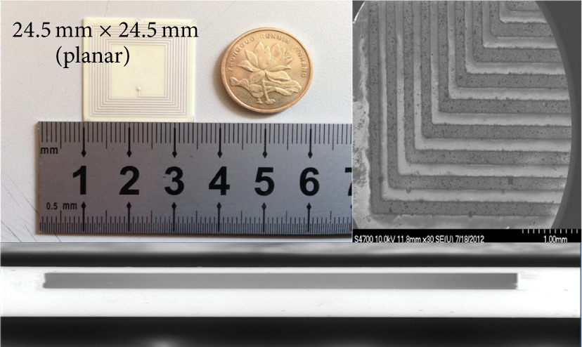
Device images: (left) microsensors; (right) micrograph of the planar spiral inductor in SEM; (underneath) micrograph of the sealed cavity.
4. Results and Discussion
The sensor testing was conducted using the PCB reader antenna connected to the readout circuit to serve as the external reader for electrical measurements. The microfabricated devices were tested on-bench to characterize their electrical, physical behaviors. Electrical parameters of the fabricated microsensor were firstly obtained by analyzing the measurement data from both the actual device with the external wireless readout method and several test structures with on-chip probing. Table 4 lists the experimental results which were in good agreement with device design estimates.
Electrical parameters of the sensors.

Measurements for the sensor were taken using pressure cylinder to simulate the high-pressure environments. The pressure can be controlled from atmospheric pressure up to 20 MPa using air pump as a source of stress and a pressure control instrument. A customized pressure control configuration, as shown in Figure 12, was utilized for wireless pressure sensing demonstration. Accurate environmental pressure variations could thus be created for the device with this pressure control setup. The device was placed inside the cylinder connected to the designed readout system to complete the high-pressure testing.

Schematic of the on-bench pressure testing setup for characterization of the sensor.
Although the pressure sensitivity was expected to be small from the device design, the sensing was compensated by the high sensor resonant frequency to reach reasonable pressure responsibility for detection of the readout circuit's dc output voltage shift with respect to environmental pressure variations. Figure 13 shows the measured dc output voltage curves for the sensor by varying the pressure from atmospheric pressure to 60 bar.

Overlay plot of the measured dc output voltage curves of the readout circuit by varying the pressure in on-bench wireless pressure sensing test.
For the sensors in the variable capacitor design, the normalized shifted resonant frequency can be written as

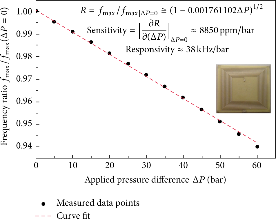
Frequency versus pressure
In the previous literatures of our research team, some static performances of sensor at high temperature are tested in the closed furnace. In this work, pressure tests are designed under 650°C high-temperature environment on the high-temperature platform as shown in Figure 17. The experiments under high-temperature environment consist of two parts in total: one is 50°C~650°C temperature changes experiment at 100 kpa and the result is shown in Figure 15; the other is pressure testing experiments with a heat preservation after 90 min under 650°C and the result is shown in Figure 16. As the platform takes water cooling way to reduce the temperature of readout antenna, the tests should be taken after the system reaches its thermal equilibrium; the pressure range is from 70 kpa to 190 kpa and step value is 20 kpa; the test results are shown in Figures 13 and 14. The resonant frequency range of sensor is 84 kHz with a linearity of 1.17% and repeatability of 7.1%, and the hysteresis is 1.94% and the sensitivity is 51 kHz/bar under 650°C as well.

The resonant frequency of the sensor versus temperature.

The resonant frequency of the sensor versus pressure at 650°C.

The customized temperature-pressure measurement system.
5. Conclusions
In this paper, a design and fabrication method of a wireless passive microsensor fabricated in HTCC technology was presented. Featuring zirconia ceramics (PSZ) and Pt inks, the sensor achieves a satisfactory performance suitable for applications in high-pressure environments. A sealed cavity, flexible ceramic membranes, and a fixed inductance L formed the series resonance circuit of the sensor, which were integrated on a monolithic substrate without the need of complex process technologies. A readout system was designed to test the sensor's resonant frequency, and the performance of the sensor was demonstrated in high-pressure environment. From the test result, the pressure dependence of the sensor can be tested up to 60 bar. The average sensitivity and accuracy of the sensor are up to 38 kHz/bar. And the results provide substantial evidence that the sensor has great potential for fulfilling continuous dynamic pressure monitoring in harsh environments.
Footnotes
Conflict of Interests
The authors declare no conflict of interests.
Acknowledgments
This work is supported by the National Natural Science Foundation of China (61335008) and the State Key Development Program of Basic Research of China (2010CB334703). The authors especially thank Dr. Xiong and Dr. Liang for their valuable comments on experimental procedures and Wenyi Liu for his valuable discussion and assistance.