
Abstract
Integration of multiple sensors into active radio frequency identification (RFID) system is a technology trend. Currently, sensing RFID (SRFID) systems face a number of challenges including description of characteristics of nonsmart sensors, management of sensor-related data, and operational mechanism of sensor sampling. Based on transducer electronic data sheet (TEDS), this paper presents a virtual description method of nonsmart sensors integrated into the active RFID tag. The objective is to improve interoperability and compatibility of the sensing RFID system with off-the-shelf active RFID readers or novel sensing RFID open-loop systems in the future. This paper also proposes a data table storage mode for management of sensor-related data, in the system based on virtual TEDS. The paper analyses the operational mechanism and procedure of the sensor-sampling system that is equipped with these two proposed techniques. Several experiments were carried out with a newly developed container supply chain monitoring application system based on SRFID to examine the performance of the system.
1. Introduction
Even though radio frequency identification (RFID) systems can rapidly collect information about items, they cannot acquire dynamic status information of items, such as temperature, humidity, and acceleration. On the other hand, sensor systems are capable of collecting all kinds of dynamic status information of items and fill the gap by RFID systems. In order to collect item data rapidly and monitor the environment status around the items, it is very important to integrate RFID with sensors. We refer to the device that integrates RFID tag and sensors, as SRFID (sensing RFID) tag. However, designers are confronted with the several challenges when they attempt to integrate sensors into an RFID tag, especially when the SRFID tags are used in large scale or open-loop systems.
The First Challenge Is the Nonsmart Sensor's Description. In future SRFID tags, the number and type of sensors can be different according to specific application requirements. In addition, models and parameters of sensors from different manufacturers differ from one to another even if these sensors are of the same type. The following problems are recognized when these diverse sensors in the SRFID tags are identified and configured by off-the-shelf readers in a standard way: (1) unique differentiation of sensors in a SRFID tag by the reader; (2) automatic recognition of types and basic parameters of sensors; and (3) effective configuration of sensors’ parameters. When the sampling datasets collected by the sensors are transferred to the reader, parsing and interpretation of these datasets represent additional problems.
These problems are related to a sensor's description. Sensor's description provides basic characteristics of the sensor and interoperability between SRFID tags and readers or host applications. However, general-purpose digital and analog sensors do not have such self-description functions and do not have the capability to describe themselves.
The Second Challenge Is the Sensor-Related Data Storage in the SRFID Tag. Potentially, there will be many diverse sensors in a SRFID tag and the number of sensors may vary in different SRFID tags. Therefore, there is a need for simple, flexible, and effective data storage method. Because the interfaces of various sensors are different, we need to unify API methods to access all the sensor-related data and control all the sensors in the SRFID tag by the reader. Besides, this storage mode should allow a designer to conveniently append a sensor into the tag or remove a sensor from the tag.
The Third Challenge Is the Operational Mechanism of Sensor Sampling. Based on the sensor's self-description and data storage, it is necessary to set up an operational mechanism of acquiring sensor parameters, configuring sampling parameters, and collecting and parsing sampling data.
In this paper, we will focus on sensor self-description, sensor-related data storage management, and operational mechanism of sensor sampling for sensors integrated with an active RFID tag. This study is limited to self-description of a sensor and it does not consider features of plug-and-play (PnP).
The remainder of this paper is organized as follows: Section 2 gives an overview of integration of RFID and sensors that is relevant to our work. Section 3 presents sensor self-description design with virtual TEDS. Section 4 presents sensor-related data storage approach in the SRFID tag. Section 5 discusses the operational mechanism of SRFID system. Section 6 introduces the implementation and experiment with the SRFID system. Finally, conclusions are drawn in Section 7.
2. Related Work
This section covers two aspects of related work: a sensor's description and a management method of sensor-related data in the sensor node.
2.1. Sensor's Description
Sensor's description is about sensor's characteristic parameters and it involves sensor's plug-and-play technology. There are two main technologies for device PnP: Universal Plug-and-Play (UPnP) and Java Intelligent Network Infrastructure (Jini) [1]. The UPnP description for a device is expressed in XML and includes vendor-specific manufacturer information like the model name and number, serial-number, manufacturer name, URLs to vendor-specific web sites, and so forth. In the Jini, each network device is described as some service, and these services can be published automatically and be invoked by user. Implementation of UPnP or Jini needs significant computing resources and this is not suitable for application in sensors. Sensor PnP is also a kind of device PnP. Sensor plug-and-play has six features, such as ability to announce a sensor's presence, automatic discovery of a sensor's presence, ability to describe sensor's capabilities, sensor self-configuration, control sensor's function, and sensor's event function. Sensor's description is one of six features of smart sensor plug and play.
For smart sensors’ PnP, there is a dedicated industrial standard IEEE1451 that defines software and hardware interface of the transducer (sensor or actuator). A part of the standard, namely, IEEE1451.4 is about a sensor's description technology with transducer electronic data sheet (TEDS). Many legacy smart sensors adopted TEDS to describe sensors’ characteristic parameters, and almost all research papers in this field are based on TEDS to describe sensors’ characteristic parameters [2–7]. TEDS describes related parameters of the sensors, such as the name of the sensor manufacturer, the type and serial-number of the sensors, and other self-descriptive data. TEDS data could help the host-device identify the related parameters of the sensor and help the sensor connect to the host-device, by providing the self-description parameters of the sensor. The TEDSs are usually stored in the built-in EEPROM of the smart sensor node and accessed via the 1-wire protocol or other protocols.
There are some nonsmart sensors, such as legacy analog sensors and digital sensors, which do not have any TEDS datasets for self-description. Virtual TEDS technology can help these sensors implement self-description feature. These virtual TEDS datasets could be stored in a local computer or online databases. Figure 1 shows the block diagram of virtual TEDS system defined in IEEE1451, with the smart TEDS sensor on the left side and virtual TEDS sensors on the right side. If the host-devices need to identify the parameters of nonsmart sensors, they can get access to the related memory where virtual TEDSs are stored.

Virtual TEDS system in IEEE1451.4.
Regarding integration of RFID and sensors, the related standards include IEEE1451.7 [8], ISO/IEC/IEEE 21451-7 [9], and the ISO/IEC24753 [10]. The standard IEEE1451.7 mainly specifies sensor security and data structure, the interface between the sensors and the RFID tag, the integrated architecture framework of the sensors, and the RFID command for the sensor operation and RFID communication. This standard highlights the integration of the RFID system and the full function sensors. The standard ISO/IEC/IEEE21451.7 is similar to the standard IEEE1451.7. The standard ISO/IEC24753.2 mainly specifies the application interface model for integration of the RFID tag and the sensors, the data structures, application commands, and the corresponding responses of a full function sensor and a simple sensor. These three standards present integration solutions for RFID and smart sensors and also describe how to develop a smart sensor that can be integrated with RFID system. However, they do not deal with integration of existing analog or digital sensors into RFID tags. These nonsmart sensors need more consideration regarding their integration with RFID tags.
2.2. Management Method of Sensor-Related Data
There are many models and description methods for sensor-related data management. The sensor web enablement (SWE) initiated the open geospatial consortium (OGC) that has standardized web service interfaces and data encodings as building blocks for the sensor web and has proposed sensor modeling language (SensorML) [11]. The W3C semantic sensor network (SSN) incubator group put forward SSN ontology description [12, 13]. Berkeley Manufacturing Institute, University of California, presented TinyML—metadata for wireless networks [14]. The Universal Plug-and-Play (UPnP) Forum standardized sensor data description model [15]. Sensor descriptor definition language (SDDL) is presented in [16] while the metadata language for sensor description, starfish fungus language (StarFL), is described in [17]. However, all these sensor-related data description methods are used in the host-computer or at the network level but not at the sensor node level. These methods are based on the XML language, which has too much format information, consumes large memory space, and needs XML parser to resolve them. In addition, sensor nodes have limited resources; therefore XML file is hard to implement the data retrieval, data removal, data modification, and the like. Therefore, these methods are not suitable for application in the sensor node, and we need a new method to store sensor-related data in the SRFID tag.
In terms of sensor-related data management, there are also many published methods. In [18], a data storage framework for structured/unstructured RFID or sensors data at the level of cloud computing is proposed. The solution in [19] proposed data structures of heart rate sensor and blood pressure sensor in the middleware and [20] described three sensors’ data with XML language in the mobile sensor framework. Works presented in [21, 22] did not mention sensor's description and sensors data management when sensors were integrated into RFID tag. In [23], a sensor's description is presented but without sensor data management solution. Work in [24] proposed a series of data models of sensor, sensor node, session, sensor value, sensor location, and sensor event. The work in [25] divided the memory of a tag into numerous 64-bit blocks and then further divided these blocks into two parts, one for the counter and the other for the sensor data. Solutions in [24, 25] presented preliminary sensor data management solutions; but without a sensor's description and effective data management, these solutions have poor expansibility in an ultra large scale system or open-loop system. Therefore, better solutions are needed for sensor data storage and management in the sensor node, especially with multiple sensors at the sensor node level.
3. Sensor Self-Description Design with Virtual TEDS
Sensor's self-description is a critical factor for compatibility of SRFID tags in ultra large scale systems or open-loop systems and its standardization will also benefit the storage of sensor-related data. In this section we present a realization method of the sensor virtual TEDS, as well as the design of virtual TEDS in the tag and corresponding templates in the reader.
3.1. Hardware Architecture and Storage of Virtual TEDS
A traditional active RFID system consists of active RFID tags, reader, and host-computer application. When physical sensors are integrated into the RFID system, the system becomes a SRFID system. The components of SRFID system are shown in Figure 2. The SRFID tag consists of an active RFID tag and several sensors. It has the functionality of active RFID tag and it is also in charge of the sensors. It configures sensors’ parameters, collects and stores sensory data, and transfers sensor-related data to the reader. The reader receives and processes all the data from the SRFID tag and then transfers the processed data to the host-computer application. The host-computer application receives and further processes data as well as execute some business operations.

Component architecture of the SRFID system.
To minimize tag dimensions and cost, sensors selected in the tag need to be small and common digital or analog sensors, which are nonsmart and therefore cannot describe themselves. In order to describe parameters of these nonsmart sensors, we design virtual TEDSs for every sensor, which stores parameters of these sensors and all virtual TEDSs in the built-in memory of the active RFID tag. The dataset contents of TEDS will be introduced in this section and the storage mode will be introduced in Section 4.
When the readers control sensors in the tag or collect sensor data from the tag, they should access virtual TEDS of the sensors first to get the parameters of the sensors. These SRFID tags should be compatible with existing readers and host-computer applications, adopting the same air communication protocol. Compared with wireless sensor network (WSN), SRFID tag is similar to a sensor node in WSN, and SRFID reader is similar to a sink node. SRFID system is one-hop communication system while WSN system is multihop system. Therefore, virtual TEDS and some ideas in the next section are universal and can be used in the WSN and other sensor networks.
3.2. Virtual TEDS Design of the Sensor
Figure 3 shows virtual TEDS in the SRFID system. Virtual TEDS design of the sensor mainly involves two parts: (1) sensor's TEDS dataset in the EEPROM of SRFID tag and (2) TEDS software in the reader to decode the TEDS dataset from the tag. TEDS dataset is stored in compact binary stream format without any structure information. After TEDS software receives the TEDS dataset, it invokes the data structure templates and data code-mapping rule to parse the TEDS dataset in order to obtain decoded sensor information. The following contents will focus on these two parts.

Virtual TEDS in the SRFID system.
(i) TEDS Dataset in the SRFID Tag. Each sensor is designed with two virtual TEDS datasets stored in the EEPROM of the tag, namely, the sensor ID TEDS dataset and the sensor characteristic TEDS dataset.
The main function of the sensor ID TEDS dataset is to identify the physical sensor uniquely, and this dataset is read-only. The sensor ID TEDS is formed by 64-bit dataset and includes manufacturer-ID, model-number, version-letter, version-number, and serial-number, which are shown in Table 1. The manufacturer-ID has corresponding manufacturer-ID code template table in the reader or the host-computer application. In most cases, there is no need to parse the ID TEDS and it is only regarded as the unique identifier of the physical sensor, which is similar to the MAC address of the network interface card.
The sensor ID TEDS (IEEE1451.4).

The main function of the sensor characteristic TEDS dataset is to describe the physical sensor type and its basic parameters. The reader can identify the sensor and configure the sensor parameters automatically. The sensor characteristic TEDS consists of 80-bit dataset and the length of every field is shown in Table 2. For a new nonsmart sensor integrated into the tag, we can read the product specification to get sensor-related parameters in the TEDS and construct the sensor's virtual TEDS. TEDS-TYPE is to realize the TEDS extension capacity as specified by IEEE1451.7 [8]. PHYSICAL-SENSOR-TYPE and TYPE-EXTENDED are used to encode different physical types of sensors. For example, the sensor code for temperature is 31, and sensor type code is mapped by specific code-mapping table in the reader. LOGICAL-SENSOR-MAP is mainly to map the various logical functions defined by the physical sensor, so that one physical sensor can carry out several tasks of logical sensors, and the logical sensor has specific code-mapping table in the reader. It also relates to some data structure templates of the sampling data of sensor which will be discussed in the following sections. DATA-TRANSFER-FORMAT defines the length of the unsigned number in sensor's transmission and has specific data structure template in the reader. SCALE-FACTOR-SIGNIFICAND, SCALE-FACTOR-EXPONENT, SCALE-OFFSET-SIGNIFICAND, and SCALE-OFFSET-EXPONENT define the measuring range of the sensor and its calculation method is supported by specific examples in IEEE1451.7. The calculation process is carried out by the reader. DATA-PRECISION formulates the relative error of the sampling data and it has specific code template table in the reader. SENSOR-CONFIGURATION defines whether the parameters of a digital sensor can be configured or not, where 0 stands for nonconfigurable and 1 stands for configurable. USE-FOR-FUTURE field is for extending the length of characteristic TEDS, and it is reserved for the future.
The sensor characteristic TEDS.

(ii) Templates in the SRFID Reader. The reader has two kinds of templates for parsing and interpreting compact virtual TEDS datasets. The first kind of templates is the compact TEDS data structure templates, which mainly provides two data structure templates for decomposing two TEDS datasets, namely, the sensor ID TEDS dataset and the sensor characteristic TEDS dataset. The data structure templates of two datasets are stored in the EEPROM space of the reader, and their data structures are shown in Tables 1 and 2.
The second kind of template is the code-mapping table whose function is to match the code values with the actual physical meaning and some additional information. There are many code-mapping tables, such as PHYSICAL-SENSOR-TYPE table, TYPE EXTENDED table, LOGICAL-SENSOR-MAP table, DATA-TRANSFER-FORMAT table, and DATA-PRECISION table. Every code-mapping table has a series of code values referred to as the IEEE1451.7 standards [8]. The PHYSICAL-SENSOR-TYPE table defines the physical quantity type of the sensor. The fields of the table include physical sensor type code corresponding to physical quantity and unit of physical quantity which relies on unified international standard. The TYPE EXTENDED table encodes the chemical substance sensors, and its fields include type extended code and corresponding chemical substance sensor. The LOGICAL-SENSOR-MAP table includes two fields, the logical sensor code and logical sensor function. The DATA-TRANSFER-FORMAT table includes two fields, the data transfer format code and the transfer format definition. The DATA-PRECISION table includes two fields, the data accuracy code and data accuracy definition.
4. Sensor-Related Data Management
4.1. Requirement Analysis of Sensor-Related Data Management
(i) Sensor-Related Data. For every sensor in the SRFID tag, there are four kinds of sensor-related basic data. They are sensor identification data, sensor parameter data, sensor sampling-configuration data, and sensor-sampling data. Sensor identification data is to uniquely identify each sensor in the world, and sensor ID TEDS dataset can be used as an identifier of a sensor, as is shown in Table 1. Sensor parameter data is used to describe basic performance parameters of a sensor and sensor characteristic TEDS can be used for describing sensor parameter data, which is shown in Table 2. The sensor-sampling data is the dataset that the sensor acquires during the period of monitoring.
These four kinds of sensor-related basic data should be stored in the memory of the tag for the following reasons. Firstly, the RFID tag is not always in the coverage of fixed readers. When the RFID tag leaves the reading zone of the reader and the reader cannot acquire data from the tag for a long time, some sampling data from the sensors in the tag must be stored temporarily in the tag's memory. Secondly, network is not always available. In container supply chain application, when the container with mounted SRFID tag is in the container yard or in-transit, where there is no available network, handheld reader cannot parse the sampling data without characteristic and configuration parameters. Therefore, characteristic and configuration parameters are stored in the tag. Thirdly, in some systems, there are many types of SRFID tags and each type of sensing RFID tags can have different sensors with each sensor having different parameters and configuration. In order to interpret the sensor-sampling data from the SRFID tag, readers must get quickly basic information of sensors in the tag, such as sensor features, configuration, and the like. Therefore, additional computing and communication resources are required in order to respond to many readers quickly if a large number of sensors’ characteristic and configuration parameters are stored on the web. However, if these characteristic and configuration parameters are stored in the SRFID tag, they consume small memory space in each tag and have quick response.
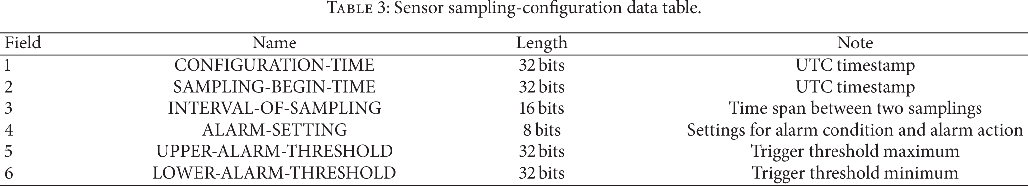
The sensor-sampling configuration data is used to control sampling and set alarms for the corresponding sensor. The parameters include timestamp when the sensor is configured, time instant when the sensor starts sampling, time span between two sampling instances (sampling period), trigger threshold of the alarm, settings for alarm conditions and alarm action, and so on. Sensor configuration-sampling data are shown in Table 3.
Sensor sampling-configuration data table.
(ii) Storage Mode of Data in the Tag. The sensor-related data may be stored in the EEPROM space of the SRFID tag in two modes, namely, the compact data storage and the data storage with format information and contents. The former can save memory space through applying binary data stream. The latter mode is more flexible regarding organizing and parsing data. For example, the IEEE1451 standards provide the TEDS in text format and allow the manufacturer to use XML language. Although the storage capacity of active SRFID tag is much larger than that of the passive RFID tag, its space is still limited and is in the range of several kilobytes to hundreds of kilobytes. The tag allocates a large space not only for static feature information but also for sampling data from multiple sensors. In addition, if sensor-related data is stored with significant formatting overhead, this would result in occupying more memory and consuming more power to transfer data to the corresponding reader. For a mobile device, memory and power are limited resources, and it is important to reduce transmission throughput as much as possible. Therefore, the compact storage mode is adopted without format information for sensor-related data in the SRFID tag.
(iii) Interoperability. Even though there are several various sensors in the SRFID tag with different sensors’ parameters and sensor-sampling data formats, we need to unify API methods to access all the sensor-related data and control all the sensors in the SRFID tag. APIs of sensors from various manufacturers are different so that we cannot provide a dedicated API for each sensor because this would require also changes in the reader for every tag with new sensors. Therefore, we must encapsulate all the different API methods in the tag and standardize the access method of sensor-related data. It is important to design a simpler, more flexible, and more effective data storage method to deal with sensor-related data in the SRFID tag. Besides, the storage method of sensor-related data should allow for convenient integration of new sensors and removal of integrated sensors, and the existing readers can access this data without any change of the air protocol between tags and readers.
4.2. Data Structure of Sensor-Related Data Storage
In this section, a new management method of sensor-related data with data table is proposed.
(i) Design the Data Structure. This paper proposes a data table method to store sensor-related data in the SRFID tag. In this table, each sensor has a record with four fields for four kinds of sensor-related data described in Section 4.1. Each field stores sensor-related data, and data value in each field is in compact structure storage mode. The reader can access the sensor-related data and control the sensors through reading or writing data directly to/from this table without knowing the access and control methods of an individual sensor, as shown in Figure 4. The data table of sensor-related data acts like a bridge which connects the reader and all the sensors and hides the details of an individual sensor from the reader. Therefore, the reader can access all the sensor-related data and control all the sensors by operating the data table, without knowing the details of every sensor and their operation commands.

Table of sensor-related data in SRFID tag.
In this data table, there are four fields as shown in Table 4, namely, SENSOR ID TEDS, SENSOR CHARACTERISTIC TEDS, SENSOR SAMPLING CONFIGURATION, and SENSING DATA ADDRESS. These four fields are matched with sensor identification data, sensor parameters data, sensor sampling-configuration data, and sensor-sampling data, respectively. The field SENSOR ID TEDS is totally 64 bits in length as shown in Table 1, the field SENSOR CHARACTERISTIC TEDS is totally 80 bits as shown in Table 2, field SENSOR SAMPLING CONFIGURATION is totally 152 bits as shown in Table 3, and field SENSING DATA ADDRESS is 16 bits. The field SENSING DATA ADDRESS only stores the address that points to the sensor-sampling data in the EEPROM of the tag.
Records of the sensor-related data.

Table 4 of sensor-related data is stored in the SRFID tag. Due to the limitation of storage capacity in the tag and the increase of sensor-sampling data, a strategy of memory rollover is adopted. The maximum memory of sampling data is defined, and the earliest record is overwritten on a first in first out (FIFO) basis at the instant when the memory becomes full.
The TEDS dataset templates and the code-mapping table involved in the TEDS dataset are stored in the reader as illustrated in Section 3. The readers are responsible for parsing the compact TEDS datasets and matching the codes in the TEDS datasets, which will be illustrated in Section 5. The tag is responsible for reading the overall sensing data from its memory according to the first data address and the reader is responsible for analyzing this data.
(ii) Pros and Cons. This data table storage method has the following advantages for multiple sensors in the SRFID tag. In the data table every sensor has a corresponding record and all the sensor-related data of this sensor is stored in this record. All the commands from readers to sensors can be executed by operating the table in the tag. Adding a new sensor or removing a sensor from the SRFID tag only requires a record in the table to be appended or deleted. Accessing the sensor-related data can be done by reading the corresponding record of the sensor from the table. Controlling the sensor is done by rewriting the corresponding record of the sensor without operating the sensor directly. By utilizing the data table, we can rely on the original air protocol between RFID reader and active tags. In this way, it is possible to unify the interface of APIs of different sensors. On the other side, it is still possible to integrate some smart sensors into active RFID tag.
However, this storage method requires the tag to control the table. In the tag, we need to implement all the universal operation methods of the table, which requires more processing capacity of the microcontroller unit (MCU). In addition, if we integrate a smart sensor into the RFID tag, there will be redundant TEDS datasets in the data table. These drawbacks are negligible for interoperability or integration in an ultra large scale system.
5. Operational Mechanism of SRFID System
Based on virtual TEDS and the storage method of sensor-related data, this paper sets up the operational mechanism and procedure for reader to control sensors and to manage the sensor-related data. For the SRFID tags that readers have not accessed before, the readers need to follow three-stage procedure to get access to the sensor-related data. The first stage is to acquire the TEDS dataset from the tag; the second is to configure the sensors in the tag; and the last is to collect sampling data from the tag, which is shown in Figure 5. The sequence of operational procedure is illustrated by number designation in this figure. The following content will focus on the information flow procedure, while neglecting the security authentication procedure between the tags and the readers.

The process chart of the data collected by sensors.
5.1. Acquisition of Parameters of Sensors
Firstly, the reader sends a wireless sensor table query command with some sensor's parameters (such as the sensor type or all sensors) to the tag, to select a suitable sensor. The MCU in the tag queries the records of the table in the tag according to the command of the reader and returns the query result with sensor ID (sensor ID TEDS field) and its parameters (sensor characteristic TEDS field) to the reader.
After the reader receives the TEDS datasets of the sensors, the MCU in the reader invokes the characteristic TEDS dataset structures template prestored in the tag, to parse the characteristic TEDS dataset and decompose the separate value of every parameter of the sensor. Because values of some data unit are code data, the MCU in the reader continues to invoke the relevant code-mapping tables prestored in the reader to match these codes with actual physical meanings or values. In this way, the values of the sensors’ parameters are obtained by the reader.
5.2. Configuration of Parameters of Sensors
After the reader parses all the sensors’ parameters, these parameters would be shown on the screen of terminal. The users can select the sensor of interest and set the value of the sensor's sampling parameter and other sensor's parameters. Then the reader packs these parameters into TEDS datasets according to TEDS data structure templates and transfers them to the SRFID tag. The tag finds the corresponding record and updates its fields in the table. After that, the tag will trigger the sensor to sample according to the start time instant and conditions of sampling.
5.3. Collection of Sensor-Sampling Data
When the reader sends an air command with certain parameters to the tag to collect the sampling data, the tag queries the table with the parameters and gets the beginning address of sensor-sampling data in the field SENSING DATA ADDRESS. The tag reads the whole sampling datasets and transfers them to the reader wirelessly.
A series of data structure templates are stored in the reader. When the reader receives the sampling data, it invokes the corresponding data structure template first and parses the whole sampling datasets into many individual data units. Then the reader obtains features of these data units, such as physical meaning, data type and length, and data precision, through mapping them with parsed TEDS datasets. For some codes in the data unit, the reader needs to invoke the code-mapping table to match these codes and to get actual physical meaning and measurement unit of the sensor physical quantity.
After the reader parses the sampling datasets acquired by the sensors, it will repack the sensor ID TEDS dataset, the sensor characteristic TEDS dataset, sensor-sampling dataset, and other related data into the XML files according to the format of sensor web enablement standards developed by OpenGIS [12] and will upload them to the host-computer application according to the application requirements. The host-computer application can effectively interpret these XML files and implement subsequent procedure, which includes displaying data on the screen and storing the XML file into the relevant XML database directly.
6. Experiments
According to the application requirements, a novel sensing RFID tag and reader system for the container supply chain were developed and tested.
6.1. Application Requirements
With the development of information technologies, automatic identification technology and internet of things can meet growing requirements for monitoring environmental conditions in smart container supply chain. In container transportation it is important not only to know static attribute information of goods such as types and quantities but also to measure their dynamic information including temperature, humidity, acceleration, and the status of container door. For example, when seafood, fruits, or vegetables, oil, drug, chemicals, dangerous cargo, high-value goods, and so on are transported, people often need to monitor environment status of these goods to prevent them from being damaged or stolen. There are four main requirements in containers supply chain, namely, monitoring status, tracking location, identifying goods, and acquiring information about goods rapidly. In supply chain, there are many solutions where RFID and sensor technologies are integrated [26–31].
In this project, we designed a novel SRFID system, which is used for monitoring condition of goods loaded in container and status of container doors during the transportation of goods in the container. This system not only has the performance of an active RFID system but also senses the environmental condition in the container.
There are two types of data structures on static information of items in the container. One is serialized data structure, such as container shipment information, and the other is data table structure, such as detailed information of all the items in the container. The sensor-related data, which is dynamic environment status information of items, is also stored in the data table. The sensing RFID system adapted the standard ISO18000-7, and this standard provides commands to operate these two data structures. Therefore, two types of data structure can coexist well.
6.2. Development of Tag and Reader
In this SRFID system, the tag contains active tag module and sensors module, and these two modules are wired together. The sensors module contains temperature and humidity sensors, accelerometer, and light sensor as shown in Figure 6. As a mechanic device, the container door switch sensor is not on the board. We implemented partially the active RFID air interface standard based on ISO/IEC 18000-7 [32], which has provided a large number of commands for table operations, such as create table, delete table, insert a record, delete a record, append a record, read a table, write a table, and query a table. However, the ISO/IEC 18000-7 standard was not used to acquire all sensor-related data but only for item static data. We implemented all the functions related to table operations to handle data table.

The integrated circuit board of the sensor module.
We used Protel software to design and develop the hardware of the novel SRFID tag and Keil software development tools to develop embedded software in the tag and reader. Also, we used visual C++ and C# to implement DLL and demo applications in host-computer application software.
In this SRFID project, we analyzed and designed virtual TEDS and data table for sensor-related data, based on the capabilities of table operations in the tag. We constructed the virtual ID TEDS and characteristic TEDS for each sensor. All the sensors were described with virtual TEDS in the memory of SRFID tag according to the description in Section 3. These virtual TEDS datasets and other sensor-related data of each sensor were organized and stored in the corresponding record of the data table as illustrated in Section 4. This table was created in the EEPROM of the tag by the microcontroller. The procedures for sampling and parsing sensor data were implemented according to the analysis in Section 5.
6.3. Testing
After the SRFID system was developed, experiments, product testing, and certification were carried out. We carried out the experiments in four container supply chain scenarios including container embarkation point, in-transit point, entrance to a yard, and container yard.
We mounted the SRFID tag on the container door, as shown in Figure 7. The sensors module of the tag was inside the container, as shown in Figure 8, and it was responsible for sampling environmental conditions in the container and transferring sampled data to RFID tag module. The RFID tag module was outside the container and was responsible for accessing the table of the sensor-related data and transferring the data to the fixed SRFID reader or handheld SRFID reader using active RFID protocol.

RFID tag attached to the container door.

The sensing tag.
At the container embarkation point, we configured all the sensors in the SRFID tag and wrote the item information into the tag with handheld reader. During the container transportation, the sensors sampled temperature, humidity, vibration, and light inside the container and recorded time when the container door was opened. A fixed reader was placed at the in-transit crossroad and was used to read data about container shipment and receive the alarm signal. The reader received the data and parsed them before the data were transferred to the host-computer application. When the container arrived at the entrance of the container yard, another fixed reader read all the information of items in the container and alarm information before the container came into the yard. When the container was placed in the yard, a handheld reader detected the container status data. The data from the readers was transferred to the host-computer application and shown on the display. The screenshot of demo application software interface for sensors configuration and sampling is shown in Figure 9.

The screenshot of demo application interface.
At the same time, testing and certification were also performed by the Chinese National RFID Product Quality Testing Center in January, 2012. The testing activities included indoor and outdoor testing. Part of the testing result is the following. The data rate between the reader and the SRFID tag was 250 kbps, and the storage capacity of the SRFID tag was 64 K bytes. The maximum communication distance between tags and the reader was 125 meters when the tag was mounted on the container door; and it was 280 meters when the tag was put on the plastic racks. When the tag was mounted on the container door, the fixed reader could read the tag ID number from the tag whose speed was 70 km/h. The sensing RFID tag was able to sample the status values of temperature, humidity, and vibration inside the container and it could also give an alarm when the container door was opened by an unauthorized person.
7. Conclusion
Integration of sensors into RFID system is not only a trend but also a need nowadays. However, there are several challenging problems related to integration of sensors and RFID tags including parameters’ description of a nonsmart sensor, management of sensor-related data, and operational mechanism of sensor sampling. This paper focuses on addressing these problems in SRFID system. It proposes virtual TEDS technology to describe parameters of nonsmart sensors in the tag, puts forward the method with the data table to manage the sensor-related data effectively, and analyzes the operational mechanism of sensor sampling. Finally, validity of these ideas is verified in an experiment that deals with the container supply chain. In the future, sensor plug-and-play technology and semantic sensor network will be studied. If the function of sensor plug-and-play is implemented completely, the TEDS data will be constructed automatically by the SRFID tag without any intervention when new smart sensors are plugged into an existing SRFID tag.
Footnotes
Conflict of Interests
The authors declare that there is no conflict of interests regarding the publication of this paper.
Acknowledgment
The work presented in this paper is a partial work of Tianjin Key Technology R&D Program no. 09ZCKFGX03700 funded by Tianjin Municipal Science and Technology Commission, China.