
Abstract
Long Term Evolution (LTE) networks that are composed of macrocells and femtocells can provide an efficient solution to not only extend coverage of macrocells but also deal with the growth of traffic within macrocells. LTE is now being considered to be a vital connectivity solution for the success of the Internet of Things (IoT) because it can provide broadband connectivity to the growing number of sensing and monitoring devices and even the wireless sensor networks (WSNs). However, it is still challenging to properly allocate radio frequency resources in the handover procedure between a macrocell and a femtocell. In this paper, we propose a new handover algorithm that increases the efficient utilization of a radio frequency resource and thereby maximizes the capacity of the overall LTE network, including the femtocells within network. The handover decision criteria take into account the strength of the received signal, the radio resource reuse, and the overall capacity of the network throughput. The performance of the proposed algorithm is verified through a simulation, and the simulation results indicate that the proposed handover algorithm improves the reusability of the cell bandwidth and increases the overall capacity of the network.
1. Introduction
Personal wireless terminals, such as smart phones, can access an expanding supply of video and audio content. A large amount of multimedia services, such as mobile IPTV, is nowadays available for users, and this has exponentially increased the data traffic load on a mobile communication networks [1–3]. Moreover, the latest Long Term Evolution (LTE) technology has vast potential in that it is fast becoming universally available and can be used to connect millions of devices to the Internet that have never been connected before. LTE is now being considered to be a vital connectivity solution for the success of the Internet of Things (IoT) [4]. IoT aims to connect the growing number of sensing and monitoring devices with the goal of exchanging data or controlling these devices. Thus, LTE can be an attractive technology to provide broadband connectivity to these potentially remote devices and even the wireless sensor networks (WSNs) [5]. In this regard, the greatest challenge is to efficiently manage the limited frequency resources of an LTE network and to provide guaranteed services to the user. Recently, the use of femtocells has been proposed in order to expand the bandwidth available in LTE networks by reusing frequency resources.
Femtocells are equipped in a very small base station, and their low output power allows for a short transmission range. Frequency resources can be efficiently managed by reassigning the same frequency to the neighboring femtocells, and furthermore femtocells can be easily installed by end users by attaching the equipment to broadband connections, such as ADSL, Cable, and FTTH, that can then connect to the core mobile communications network. Mobile network operators (MNOs) can also reduce the cost of the installation of base stations and of network management as a result of the presence of femtocells in their mobile communications network. Consequently, LTE femtocells can be a catalyst for future IoT applications.
An efficient frequency allocation scheme is required in an LTE network that includes macro- and femtocells because the femtocells exist within the coverage area of a macrocell. Frequency allocation is divided into two schemes: separate carriers allocation and shared carriers allocation. In the separate carriers allocation scheme, different frequencies are assigned to macro- and femtocells, and, in the shared carriers allocation scheme, both the macro- and the femtocells are allocated in the same frequency. However, the shared carriers scheme requires additional mechanisms that can avoid interference on the same frequency [6, 7].
The shared carriers allocation can implement either orthogonal or cochannel allocation methods. For example, WiMAX or 3GPP LTE with OFDMA uses a number of orthogonal subchannels that are divided within a single frequency resource. The orthogonal allocation method exclusively allocates each subchannel to a macrocell and a femtocell. Thus, it can minimize the interference between the macro- and the femtocells. The cochannel allocation method is considered to be the best solution to share access to any subchannel to a macrocell and a femtocell [8, 9]. However, it should be supplemented with an additional mechanism that can avoid allocating a subchannel to macro- and femtocells at the same time, in order to minimize interference.
The orthogonal allocation method can be divided into a dynamic subchannel allocation method and a fixed subchannel allocation method. When there is a small amount of user equipment (UE) connected to femtocells assigned with unchangeable subchannels, the fixed subchannel allocation method has a low efficiency because unchangeable subchannels are unused. A dynamic subchannel allocation method with limited frequency resources can allocate a subchannel to macrocells and to femtocells dynamically according to the load of the traffic in the cell, increasing the overall system capacity.
In this paper, we propose a new handover algorithm that implements the orthogonal allocation method with dynamic subchannel assignment. In the proposed handover algorithm, when a handover request is triggered as a result of the UE's movement towards a femtocell, new decision criteria are applied considering the number of required subchannels for handover completion. The handover request is accepted or rejected according to the calculation of the number of subchannels required for the handover so that the overall resources of LTE network can be efficiently managed.
The remainder of this paper is organized as follows. In Section 2, we further describe LTE femtocells. Section 3 describes the proposed handover method. The performance of the proposed handover method is evaluated through simulations in Section 4. Finally, Section 5 concludes this paper.
2. LTE Femtocells
2.1. Femtocells in LTE Network
The macrocell transmissions sometimes cannot reach users in indoor environments because the thick walls of the buildings can attenuate the transmission power. Therefore, femtocells have been deployed in the indoor environments to overcome this issue. Compared to a macrocell, a femtocell is more easily deployed since it does not require modification of the network equipment. A femtocell transmits a radio signal at 20 dBm. The service area of a femtocell is limited to short range of up to tens of meters [10]. Therefore, a femtocell is characterized as a low-cost, low-power equipment. Cells for different coverage areas are usually referred to as macro-, micro-, pico-, and femtocells, which are listed in order of decreasing base station power, as shown in Figure 1 [11].

Comparison of the cell sizes.
2.2. Frequency Management Usage in LTE Femtocells
Femtocells are located within a service area of a macrocell and are operated using overlay characteristics. Due to limited frequency resources, an efficient frequency resource management method is necessary in order to enable seamless LTE communications services. In general, carrier allocation schemes are simply categorized into either the separate carriers method or the shared carriers method, depending on whether the network operators are using the same carrier frequency. Note that carrier frequencies are officially assigned to the network operator through a license, and each frequency includes several subchannels that can be assigned to a macrocell or femtocell. Figure 2(a) shows an example of the separate carriers method where each different carrier frequency is separately assigned to macro- or femtocells. In this method, the interference between the femtocell and the macrocell does not occur. Figure 2(b) shows an example of the shared carriers allocation where the macrocell and the femtocell are both assigned to the same common carrier frequency. This shared carrier method ensures high frequency utilization when compared to the separate method, but an additional solution is required to avoid interference between the femtocell and the macrocell. Most MNOs prefer to use the shared carriers method because it is usually difficult to obtain sufficient frequency resources.
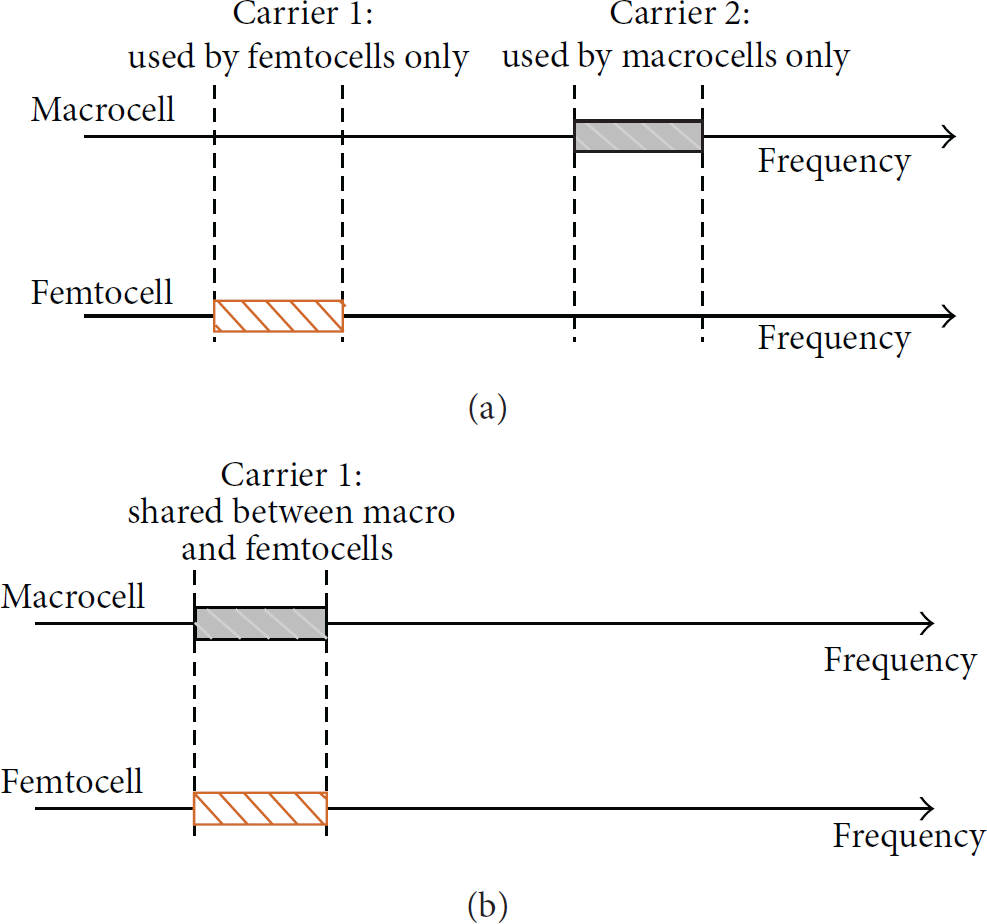
Frequency allocation schemes: (a) separate carriers scheme, (b) shared carriers scheme.
As seen in Figure 3, the shared carriers method can also be divided into an orthogonal allocation method and a cochannel allocation method, depending on the approach used for the subchannel allocation. Figure 3 shows examples of these two types of shared allocation methods. One frequency resource is divided into multiple orthogonal subchannels which are then used in 3GPP LTE or WiMAX-based networks using OFDMA. An orthogonal allocation method aims to provide exclusive access to each subchannel within the macrocell and the femtocell. As shown in Figure 3(a), a frequency resource is divided into multiple subchannels, and these are separately assigned to macrocells and femtocells. Thus, the orthogonal allocation method could be the best in terms of minimizing the interference between the macrocell and the femtocell. Figure 3(b) shows an example of the cochannel allocation method where every subchannel can be assigned to both macro- and femtocells. Thus additional measures are required to avoid interference.

Shared allocation methods.
In the orthogonal allocation method, on the other hand, a subchannel could be assigned to a macro- or a femtocell at a given time. The subchannel could be fixed or dynamically assigned to the cell. When a small number of users are connected to a femtocell assigned with a fixed subchannel, the assigned frequency usage in the femtocell is low because the subchannel could otherwise be consumed by another user in the macrocell. In such a case, the dynamic subchannel assignment of the orthogonal allocation method should be considered.
The orthogonal assignment method is the most effective because it allows for subchannel reuse in the femtocell. Also, there is no need to provide a separate interference avoidance method. In general, the subchannel is assigned to a new call or through a handover. The subchannel of the new call must be assigned without exception while the subchannel assigned to the handover call could be determined by the status of the UE and network. An efficient assignment method should be addressed for the handover on the subchannel allocation assignment in the orthogonal allocation method.
2.3. Network Architecture of LTE Femtocells
Figure 4 shows the network architecture of the LTE femtocells as defined in the 3GPP Release 10 Specification [11]. The femtocells within a home or a small office are provided with broadband network (ADSL, Cable, and FTTH) access to the core network. The costs of the mobile communication network can be reduced for both the user and the network operator by allowing for fewer installations of new base stations [12].

LTE femtocell network architecture.
Figure 4 shows how the LTE femtocell network consists of enhanced NodeB (eNB) and Home enhanced NodeB (HeNB). The HeNB gateway (GW) may be placed between the mobility management entity/serving gateway (MME/S-GW) and the HeNB in order to manage a large number of HeNBs. One HeNB will only be connected to either the HeNB GW or the MME, where a link is made through the S1 interface to the MME/S-GW or directly to the HeNB GW. The advantages of using an HeNB are that it can be deployed anytime and at any place depending on the occasion. The HeNB is connected to a different HeNB GW depending on the location of the HeNB. The HeNB GW transfers the control messages of the HeNB and the traffic data between the HeNB and the MME/S-GW to the evolved packet core (EPC), and it relays the data traffic from the EPC to the HeNB. In other words, the HeNB GW plays the role of eNB and MME from the perspective of the MME and HeNB, respectively. The X2 interface between the HeNBs is defined in 3GPP Release 10, and, therefore, a handover procedure could be made between the HeNBs through X2 interface without any mediation of the MME [13].
3. Proposed Handover Algorithm for LTE Femtocells
In this section, we describe the LTE femtocell transmission network structure and the proposed handover algorithm, considering the overall resource management. In this paper, we assume that the LTE network includes a macrocell and femtocells. Therefore, the proposed handover algorithm can be applied in micro- or picocells as well. The handover algorithm operates on a UE moving from the macrocell to a femtocell, and the handover request could either be accepted or be rejected by using the proposed algorithm. The overall resources could increase by preventing a handover that requires additional resources.
3.1. Femtocell Network Architecture
Figure 5 shows the network architecture of the LTE femtocell network that is considered in our work. When the UE moves to the coverage of a femtocell, the femtocell should provide a scheduling block (SB) to the UE. Note that the SB is the basic unit used to manage resources. If no resource is available at the femtocell, the femtocell sends a request message to the resource management system (RMS) in order to increase the SBs provisioned for the femtocell. The granted SB is then offered to the UE incoming to the cell. The RMS manages the availability of the SBs by responding to request messages sent from the femtocells. The RMS exists by providing a form of the functionality of the HeNB GW of the core network and the eNB.

Network architecture of LTE femtocell.
3.2. Proposed Handover Procedure
Algorithm 1 shows the proposed handover algorithm. The decision for the execution of the handover is made according to the type of UE service and the requested resource. The resource requested for handover to the femtocell is differentiated by the type of UE service, which could require a guaranteed bit rate (GBR) or non-GBR. The handover admission is decided according to these requested resources. In order to provide continuous service for the UE, GBR traffic that is triggered to a femtocell demands QPSK modulation while non-GBR traffic demands 64QAM modulation, corresponding to the best signal quality. The detailed description of the procedure is as follows.
UE that is connected to a macrocell moves to the area of the HeNB femtocell and detects the signal of the HeNB. UE compares the signal strength against the threshold value configured in the macrocell. The handover procedure is initiated in the case where the signal strength is larger than the threshold value. eNB requests the data rate to the femtocell HeNB corresponding to the current service of the UE. The HeNB decides whether the request can be accepted or not. If the SB that is to be assigned to UE is available in order to continue the service of UE, the request is accepted. However, if the SB availability is not adequate to continue the current service of the UE, HeNB asks the RMS to assign more SBs. The RMS compares the increase in the SB used in femtocell against the SB used in the macrocell. That is, a comparison is performed between the present resources and the subsequent resources following the handover for the RMS to accept the handover request from the femtocell. The request is accepted in the case where the upcoming resources increase, and then the resources are granted to femtocell. However, if the upcoming resources are less than the current resources, the request is denied.
Monitor signal strength of HeNB in macrocell Trigger handover procedure Send QPSK handover required Send 64QAM handover required Accept handover request Reject handover request Request SB expansion to RMS case Good or Normal: Expand SB in femtocell and admit handover case Bad: Reject handover required
We hereby describe the method used to calculate the SB in step
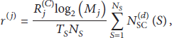

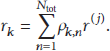
The number of SBs for the kth user is acquired as in (4), where the minimum data rate required by user k is set to

That is,

The

Parameters for femtocell service coverage.


The system's overall throughput is represented in the following equation by using (8) and substituting 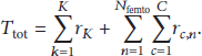
4. Simulation Results and Analysis
In this paper, the proposed method is applied to the LTE femtocell network configuration, as shown in Table 2.
Simulation parameters.
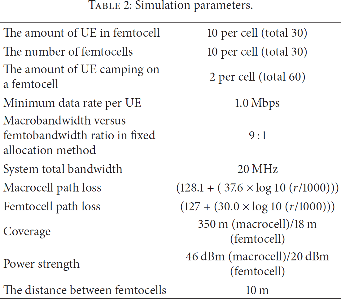
The parameters configured in the LTE femtocell network are listed in Table 2. We assume that the UE moving to the coverage of the femtocell executes the handover procedure for the neighboring femtocell. The UE camps on the femtocell after completing the handover procedure. Figure 6 shows the bandwidth variation within the femtocell. In the fixed method, although the UE moves to the femtocell, the handover procedure is not executed because no additional resources would be allocated to the femtocell.

Available system bandwidth.
In the dynamic method of the legacy allocation method, the handover procedure is executed for the femtocell without considering the resources of the femtocell. The UE moving to the femtocell either suffers from a degradation in services or moves back to the macrocell, and the resources used at UE moving to the femtocell could not be allocated to other users in the macrocell anymore. On the other hand, in the proposed method, this handover procedure is prohibited because the resources for the macrocell could be reduced. This prohibition results in an increase in the resource of the macrocell or in accommodating more users in the femtocell. The available capacity of the system increases in the proposed method when compared to the dynamic legacy method when the UE tries to move to the femtocell.
In the proposed method, the number of handovers and the available resource are observed as the UE moves through the femtocell. We assume that the UE moves through the femtocell at 1 m/s. The handover is triggered when the strength measured by the UE is more than the threshold configured in the macrocell. Figure 7 shows that the number of handovers increases according to the movement of the UE. The handover is then triggered without consideration for the system resources. This frequent handover degrades the performance of the system and of the UE. The variation in the resources available for the system is shown in Figure 8 as a number of handovers increase. The resources of the macrocell are not taken into consideration in the legacy method. On the other hand, in the proposed method, the handover is not triggered in the case where there is a possibility of reducing the system resources. The figure indicates how more resources are required in the existing methods (i.e., fixed and dynamic methods) than in the proposed method as the UE moves to the boundary of macrocell. In the proposed algorithm, unnecessary handovers are prevented, resulting in a decrease in the probability of a dropped session as well.
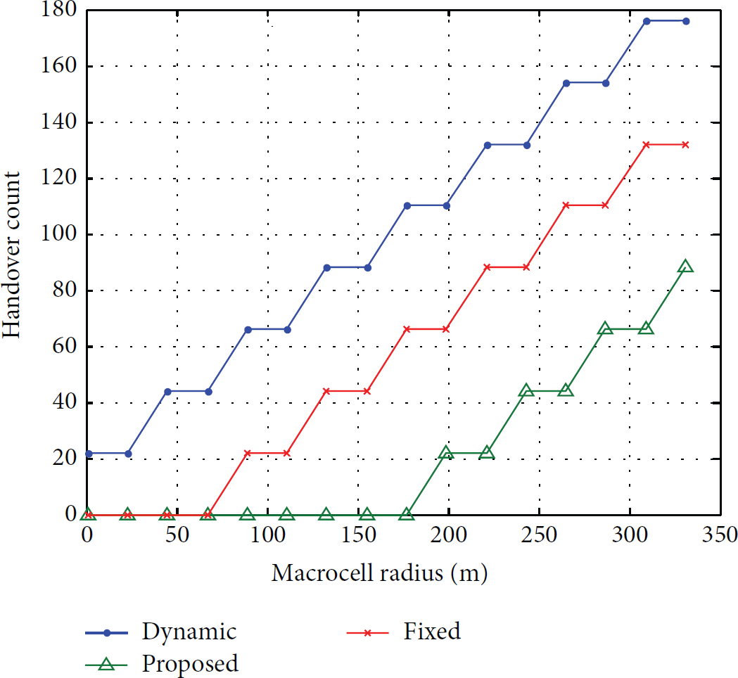
Number of handovers.

Variation in available bandwidth according to the handover to the femtocell.
5. Conclusions
The handovers in a femtocell that covers a small area have been addressed in order to accommodate the exponential increase in traffic volume of LTE networks. In this paper, we present a novel handover algorithm that considers the resource allocation of femto- and macrocells as well as the overall resources of the LTE network. This algorithm provides UE with service continuity and offers an efficient allocation of overall resources. The admission of the handover request is decided by considering the availability of resources at the femtocell. Although the available resources may allow for a handover, resource efficiency may be improved by rejecting the handover request in the case where more resources are used by UE after the handover. The purpose of the proposed algorithm is to increase the overall resources available, and its performance was verified through a simulation. The proposed method efficiently manages resources for situations in which there is an increase in the availability of SBs of an LTE network, and it also provides guaranteed service to the UE.
Footnotes
Conflict of Interests
The authors declare that they have no conflict of interests.
Acknowledgments
This work was supported by the ICT R&D Program of MSIP/IITP (B0101-14-0059, Human Resource Development Program for Future Internet). This research was also supported by Basic Science Research Program through the National Research Foundation of Korea (NRF) funded by the Ministry of Education (NRF-2014R1A1A2057641).