
Abstract
For shortcomings of current smart home system and power line carrier insufficient data transferring, an intelligent sensor networks system based on intelligent gateway is studied in this paper. Smart home system includes internal network, intelligent gateway, and external network. Multiple servers are designed in gateway, which start at the same time and receive various forms of data. Then data is processed for internal network format. External network includes several modes of communication such as TCP/IP, UDP, and pipe. Internal network includes ZigBee wireless and power line carrier (PLC) communication. Power line carrier protocol is improved, and it expands data transmission capacity to accommodate communication needs of modern family. Smart home system is designed as modules, such as intelligent gateway module, power line carrier communication module, ZigBee wireless communication modules, and appliance within electric equipment. Finally this system is physically designed and verified. The smart home system introduced in this paper has easily used and has strong compatibility.
1. Introduction
Internet of things (IOT) has become a hot issue of global concern, and people constantly put the equipment and appliances that can be associated into the network. It is also considered as one of the most significant technological innovations after the Internet. With the continuous development of Internet of things, smart home (digital home) based on it has got more attention in the world [1]. European Union in 2005 proposed “European information society strategic plan i2010-Initiative” which made the goal clearing that “Create a single European information space, improve digital communication technology research investments, and improve people's quality of life and national public services by the use of digital communications technology” [2]. In 2009, USA launched “National Broadband Plan,” which aimed to provide nationwide cable TV, high-speed Internet access, and telephone services for home user. Japan proposed “U-Japan strategy,” which establishes “ubiquitous information network” to provide more convenient way for public network information services. Smart home is studied to be smarter [3]. In China, several plans have been proposed, such as “Modern service industry technical support system and application demonstration project,” “Next Internet generation demonstration application project,” “Digital cable project,” and so on [4].
Smart vehicle space [5] and smart classroom [6] are limited in the space. Smart home is a platform of building [7], network appliances [8], communication [9], appliances automation [10], telemedicine, home office, entertainment, and other functions [11]. It provides a safe [12], convenience [13], energy saving [14], and friendly living environment [15], which includes system, structure, service, and management. Biometric access control is considered in smart home [16]. Secure wireless monitoring and control systems are studied [17]. Nowadays digital home systems within the family network are usually used by a single network, and it has a lot of limitations. Service gateway is important for smart home [18]; it should be adaptive [19]. Varieties of consumer electronics devices have to be accessed. As extensive sensors network and multimode control devices accessing, it required a gateway platform which can efficiently process varieties of protocols and heterogeneous data.
In addition, the use of technology now also has its shortcomings. Wireless technology will produce radiation, unstable performance, message leaking, and so on. Wired technologies within the family will cause inconvenience of installation. Power line carrier (PLC) technology [20] has the technology of wired and wireless technology, not only stability, but also safety. Power line communication [21] and its application in smart home [22] are studied. However, as extensive devices and sensors are linked to home platform [23], the old PLC protocol X10 is not fit for the advance of smart home.
In order to overcome the shortcoming of X10 protocol, a new power line carrier protocol is proposed in this paper. It supplements and expands X10 protocol to accommodate large amount data transmission, and it increases centralized control modes and reduces control data frame size. ZigBee network is used in information collection [24], which can also be used for home automation system [25] and energy management system [26].
In our study, smart home is designed based on intelligent digital home gateway and PLC-power line communication technology is designed as main family inner network. Intelligent gateway is based on embedded platform, which is the core part of digital home. It has a unified controller, protocol conversion, data processing, and other functions. Internet networks for personal computer, mobile phone, and mobile devices are used as external network, so it meets the requirement to connect anywhere.
2. System Architecture
Digital home system consists of three parts: intelligent gateway, external network, and internal network. It is shown as in Figure 1, where external network comprises control terminal web page, mobile control terminal, and local control terminal. The communication method is the common networks Internet and mobile networks, so user can access home system anytime and anyplace. Inner network mainly includes power line carrier network and ZigBee network used in information collection [25].

Structure of smart home.
PLC control network is mainly composed of communication technology networks by a power line carrier, which sends controlling data from intelligent gateway by a transmission module, and the data is transmitted to the power line. Then data are received by power line carrier receiving module and transmitted to control devices. ZigBee network is auxiliary network of power line carrier, used for sensors data acquisition. As there may not exist any power lines in sensors distribution, wireless communications such as ZigBee can work well. Intelligent gateway is the core of the system based on 64-bit embedded system as processing platform, which includes five servers for data processing and conversion. It achieves centralized control, format conversion, and other operations.
3. Intelligent Gateway
Intelligent gateway uses a 64-bit processor, which is a single command processor. It is allowed a great degree of parallelism in the latter pipeline, so processing rate can be greatly increased for instruction execution process. Once the instructions are decoded, they will be transmitted to different execution units for processing according to the type of operation. The speed is very close to parallel processing. Data path also includes several processing units, which allows ALU operations, multiplication operations, and memory access operations simultaneously. Moreover, the processor is not expensive and easy to use. This is the advantages of using embedded processor.
Intelligent gateway includes five servers: TCP/IP server, UDP server, pipe server, serial transceiver module server, and data conversion server. TCP/IP server, UDP server, pipe server, and serial transceiver module server are mainly used for data transmitting. Data conversion server is the core of intelligent gateway which is used for data authentication, processing, and format conversion.
TCP/IP server is a server based on the established TCP protocol, which is used to monitor and receive the external network by TCP protocol. The received data are transmitted to data conversion server. Data flow diagram is shown as in Figure 2.

Flowchart of TCP data.
TCP/IP data server receives packet and transmits to data conversion server, which validates the data. After judgment, the data is converted to PLC protocol data format. Then serial port is initialized and set up to send data. Serial data will be sent to the power line through power line carrier transmission module. PLC receiver module of controlling receives and restores the data, which are used to control electrical devices.
UDP server is mainly used for large data as camera video transmission, which is started by the signals of data conversion server. It will start running MJPEG package and UDP server after camera starts. The data are sent to video receiving terminal continually. UDP video surveillance data flow diagram is shown as in Figure 3.

The flowchart of UDP data.
Pipe server is used to receive CGI data and the data run on the local control platform. Local control data run on the same embedded platform as servers, so it is convenient to transfer data. Pipe server will automatically create server_pipe file at run time and monitor server_pipe pipeline in real time.
Received data are transmitted to data conversion server for processing. Data flow diagram detailed is shown as in Figure 4.

Flowchart of pipeline data.
Data flow method of web and local terminal is heterologous isomorphic way. The format is the same as TCP/IP data, and it also uses pipeline for data transmission.
4. Internal Network
4.1. PLC Module
PLC communication medium is a power line, which means transmitting digital or analog signals through the carrier. The signals are transformed to high frequency signals which are loaded into the power line and transmitted by a power line. After reception, high frequency signals are separated from the power line through a dedicated power line modem and sent to terminal devices. It is unique method of power system communication.
Power line carrier communication generally has the following advantages.
The medium of power line carrier is power lines, and power lines are all housing infrastructure. It does not require laying lines specially. It can save the cost of laying communication lines, and it also avoids laying network lines and redecoration such as residential drilling, external lines, and rewiring. So the house will look more tidy and beautiful. Power line is used as a communication channel. It not only can “plug and play,” but also eliminate the need for cumbersome dialing process. It accesses network once accessing to power. It will be online forever as plugging in the power. Power line carrier communication signal transmission medium is a power line, which is the high-voltage transmission and high mechanical strength medium. It has antidestruction capability, and it will not be easily occurring line fault. As long as power lines are laid well, the communication channel is established. Overall construction is fast, and there will be less investment. Power line has a wide range. Power line is the most popular network in the world. There is a power line network in any family or any place, which is the advantage that networks of telephone, cable TV, and cable networks cannot match. Electric power carrier communication can be easily used to each family for the modern family of intelligent building, and it provides a broader space for development and develops faster. It is more suitable for the general population.
A high-performance and low-cost power line carrier module is used in this paper. It integrates all required receiving and transmitting circuitry for PLC communication. It only requires a simple external coupling coil and isolated high-voltage capacitor. Then a complete minimal power line carrier application will be formed. This module volume is very compact: about 20 mm * 50 mm, with single inline pin connection mode. LED control, security control, and intelligent lighting control are ideal applications. The module has a carrier mechanism for conflict prevention and allows multiple sets of equipment to simultaneously receive data. The module carrier frequency is customizable and it can be customized according to customer demand for special control functions.
Parts of the module's principles and design are used in this paper. Some useless interfaces are deleted. Abstracted diagram is shown as in Figure 5. Improved carrier identification module size will be smaller and enough for being embedded into tube or LED lights. Needless to say, it is more suitable for the larger smart home devices.

Schematic of power line communication module.
This module is a power line carrier analysis module. Serial output hexadecimal protocol signals are transformed to electrical carrier signal and loaded into electrical equipment. On the other way, the power line signal is transformed to hexadecimal serial signals through analytical chips. Interface is provided to the IP address identification module. The same equipment is used to send and receive data. Microcontroller is designed for protocol analysis, and it is used to control appliances.
4.2. IP Identity Module
Storage module is designed in smart home device, which can record more than 256 different modes.
After integration of the original two-part feature, new design is proposed in this paper. IP module is designed in a small module which includes device settings and memory modules. Hardware of this module is quite small, and it is adequate for embedding almost all smart home devices with carrier module. The circuit is designed as in Figure 6.

Schematic of IP identity module.
4.3. PLC Protocol
As the PLC protocol X10 is limited for mass of devices, a new power line carrier protocol is designed in this paper. It is based on X10 protocol, and it improves X10. Coded addresses supported are expanded. The addresses can be expanded as needed, up to 255 * 256 addresses. It is now designed as 256 addresses coding demo for building requirement. Control protocol is designed as integration control and single control, so spending for large data is reduced. It is more flexible to control devices. Integration control is mode control, and each lamp is designed with its own separate brightness in the same mode. If you want to centralized control, you should just send a model number which only needs one byte.
Power line carrier data protocol is defined as follows.
(1) Data Definition
0x00-0xFF: 0x00-0xC7: data class (0–199); 0xC8-0xFF: frame head and tail (200–255); frame head and tail: 0xC8-0xEF: mode update frame including mode message (200–239); 0xF0-0xFF: control frame even is head and odd is tail (240–255); double-digit means hex.
(2) Detail Message of Data
(a) Data Frame Format of Update Mode. Data frame format of update mode is designed as follows: head, address group, first device and its control message, second device and its control message, …, and tenth device and its control message. It is easy to update.
Example: data string of update mode is shown as follows.
C8 00 01 32 01 32 01 32 01 32 01 32 01 32 01 32 01 32 01 32 01 32 C9.
It means that switch, RGB, and intension of ten devices in group 00 are updated.
C8: head (range: C8, CA⋯EE): the value of update mode can be calculated as head value minuses 0xC8 and division by 2. 00: address group (rang: 00 01 02⋯64): each group includes ten addresses. 01 32: switch, variable, and percentage of update device: each group includes ten devices to update. C9: tail (range: C9, CB⋯EF): tail is head plusing one.
(b) Data Frame Format of Startup Mode. It is simple for startup mode. The format of startup mode is also simple: head + mode number + tail. The mode number is according to its function as in Table 1:
data frame: F0 00 F1; meaning: devices start in mode 00; F0: frame head; 00: mode (range: 00⋯10): 10 means closed mode; F1: frame tail.
Mode and function comparison.

4.4. ZigBee Network
ZigBee communication is developed short-distance wireless communication technology recently, which has the features with close range, low power, low rate and low cost. It provides users for mobile and flexible networking, and it is ideal for family control application. In order to take the advantages of ZigBee technology and its application in modern home network application, ZigBee technology is used to realize smart home sensor data transmission. It takes advantage of ZigBee motorized and flexible features.
Varieties of sensor data are collected and processed by microcontroller chips. Then it is sent to receiving communication module with embedded board through the existing ZigBee communication module and loads through the serial data to data processing server. Finally the results are reacted to corresponding terminal top (see Figure 7).

Flowchart of ZigBee data.
5. Terminal Design
Several common terminal control modes are designed in this paper, such as mobile phone terminal, web terminal, and local touch screen control terminal. External network is primarily used for user terminal interface, which is simple and easy to use.
5.1. Phone Terminal Design
Phone software is based on mobile operating system platform which should be popular and widely used. The development is friendly, and it is easy to develop. Now several platforms have powerful graphics, sound support, and automatically manages software life period. For phone terminal, many functions are designed.
Mobile client works as follows.
Intelligent gateway is connected and logged by IP address first. Mobile client generates a command string and sends commands to intelligent gateway through socket. After it receives the commands, mobile client interprets commands and calls the appropriate service execution. States of all devices are queried when entering the interface activity so that you can ensure data synchronization and avoid multiple terminal data differently.
Main pages and monitor pages of mobile phone terminal are designed as in Figures 8 and 9.

Main pages of phone terminal.

Monitor pages of phone terminal.
5.2. Web Terminal Design
Web design is based on HTML and CGI (Common Gateway Interface) technology for pages design. Common Gateway Interface (CGI) is a web server host which provides a standard interface for information services.
CGI interface is used for writing browser data into files which are processed by httpd or cern server. It allows other users to access the interface. There are almost web servers supporting CGI.
Principle of web terminal working is shown as follows.
Browser requests a URL for CGI application through html. Server receives the request. Server judges and executes the specified CGI application. Instructions users have entered are executed by CGI. Execution results are transformed to document which browser or network server can interpret (typically html pages). Web server returns results to browser for display.
Main page of web terminal is designed as in Figure 10.
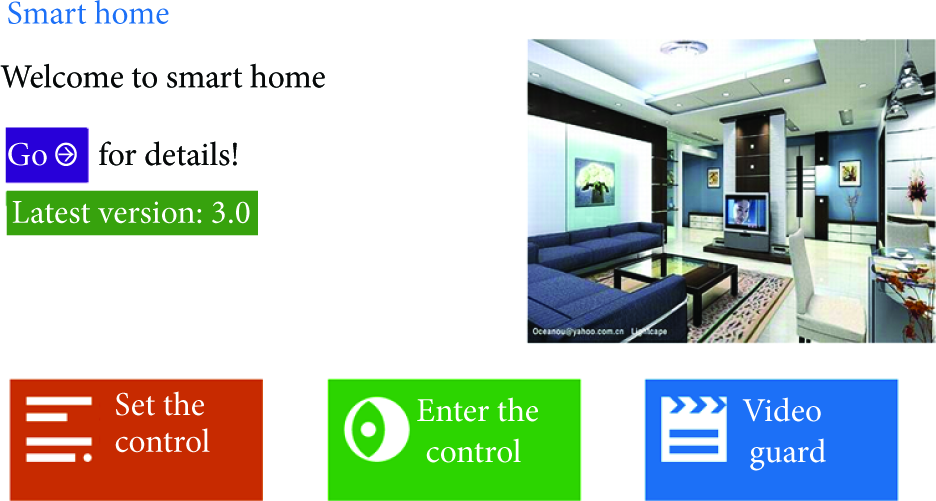
Main page of web terminal.
5.3. Local Terminal Design
Local terminal runs on embedded development board, which is developed interface using touchscreen controls embedded software. It uses a 7-inch screen. Interface designed and server run on the same embedded board, so local communication is pipe communication mode. It can avoid data conflicts with TCP/IP communication.
Local terminal works as follows.
Local control terminal runs automatically when server is turned on. Click on various modes and you will send the data to background, where data is packaged into pipeline format. Data is sent to listening pipelines of pipe server. Pipe server will extract the data and send it to data conversion server. Data is parsed and processed by conversion server. Implementation results of query or execution are piped back to terminal interface.
Main local terminal is designed as in Figure 11.
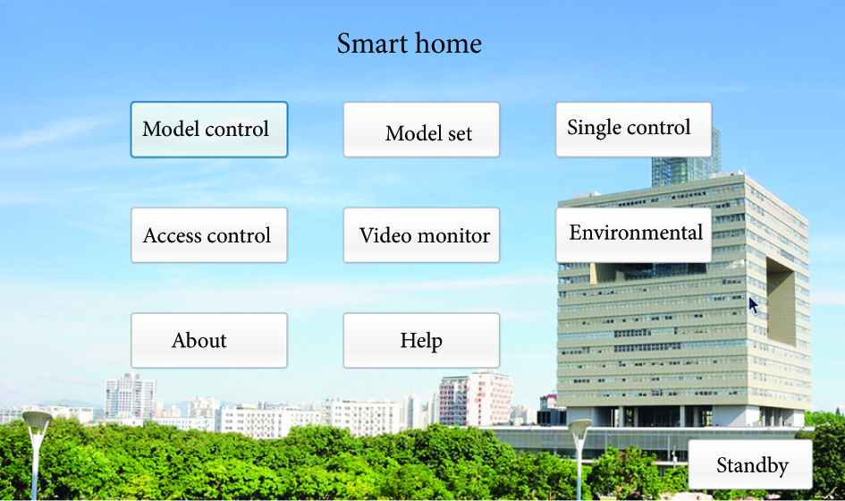
Local terminal.
6. Conclusion
For shortcomings of current smart home system and PLC insufficient data transferring, a new smart home system with several communication modes and terminals is proposed in this paper. It allows users to easily grasp home situation no matter where they are. Convenience and safety of home system are enhanced. Power line carrier protocol is improved, and it expands data transmission capacity to accommodate communication needs of modern family. Video surveillance, intelligent control appliances such as doors, windows, and other functions are realized in this system. Sensors information is collected in real-time, effectively realizing home information access. Finally this system is physically designed and verified, and it has good compatibility and stability.
Footnotes
Conflict of Interests
The authors declare that there is no conflict of interests regarding the publication of this paper.
Acknowledgments
The authors gratefully acknowledge the contribution of the National Science Foundation of China (61202159, 61273354, and 61174053), the National Key Basic Research Program of China (973 Program) under Grant no. 2014CB845301/2/3, and the Natural Science Foundation of Guangdong Province (S2011040004700). The work is also supported by Shenzhen Engineering Laboratory for Mobile Internet Application Middleware Technology.