
Abstract
In the packet access of wireless sensor networks, a distributed access protocol is employed to avoid packet collision but it also causes delay. Therefore, real time data collection is difficult. In wireless communication for simultaneous multidata collection (WC-SDC), sensed data are projected onto the parameters of the wireless communication. The specific feature of the sensed data appears in received signals. Even if the transmitted signal from each sensor collides by simultaneous access, the mixture sensed can be separated by using the specific features. Therefore, the real time data collection is achieved. However, frequency mismatch causes the fluctuation of sensed data, which gives the adverse impact to data separation. In this paper, a data tracking method is used for the data separation in the WC-SDC. We clarify the accuracy of data separation and the impact from the frequency offset. We propose a method for coping with the frequency offset and the error tracking. From the numerical results, our proposed method accurately achieves data separation even under 7% frequency offset normalized by the minimum frequency resolution.
1. Introduction
Recently, wireless sensor networks (WSN) can construct a new life style. Therefore WSN and the Machine to Machine (M2M) communication have attracted much attention [1]. Requirements for the WSN system are widely diversified. For instance, for monitoring the large scale and active natural environments by multipoint sensors [2], time delay for data collection is significantly limited. The long operating life of sensor is required because the battery of a sensor cannot frequently be recharged.
The recent standards of WSN, such as Zigbee [3] and 6low pan [4], are based on packet access. These are suitable for the communication of long life monitoring. In low-power-listening (LPL) MAC [5] protocols, the node and the fusion center construct a sleep time for saving the energy of battery. However, its packet access loses real time property. This is because simultaneous access for using the common channels is not acceptable and distributed access control causes delay [6]. The access protocol delay is also a problem for LPL. The working time of fusion center is shortened, while the collection time of all data increases due to the access protocol delay. Therefore, the collection of sensed data is not completed within the working time. Instead of the packet access, a novel wireless communication method for real time data collection is necessary.
The wireless communication for simultaneous multidata collection (WC-SDC) has been proposed in [7]. The sensed data is directly projected to the parameters of wireless communications (wireless parameters), such as time, frequency, and antenna's number. Each sensor sends the signal whose parameters are determined by the sensed data with a projection rule to the fusion center. The fusion center can recognize the original sensed data in accordance with the projection rule between the sensed data and the wireless parameters from the received signal. When the sensed data are independent in each sensor, the overlap of wireless parameters hardly occurs. Even if the sensors simultaneously access the fusion center, each signal projected by the sensed data could be detected separately, due to the independency of the sensed data. Even though the overlap of them occurs, the existence of sensed data can be detected. The data cannot be detected separately but the distribution of them can be detected. Therefore, the WC-SDC achieves the multidata collection in real time. Since the WC-SDC can collect the multiple signals from sensor, instantaneously, the fusion center and the sensor node can work for a short time in LPL MAC protocol. As a result, the WC-SDC contributes the long operating life in WSN.
The sensed data have some specific features, such as temporal continuity and the limited dynamic range. Therefore, a tracking technique, such as Kalman filtering [8], which is used for detecting the temporal continuity, can decompose each piece of sensed data from the signal transmitted by the WC-SDC. A concrete decomposing method for the WC-SDC into each piece of the sensed data has not been considered, yet. In Kalman filtering, its filter coefficients are constructed in real time, and thus the real time property achieved by the WC-SDC remains. Since the tendency analysis of each sensor's data is available from the decomposed data, the applications of the sensor networks with the WC-SDC are more widely spread.
The vulnerable points of data separation in the WC-SDC are the flickers of wireless parameters and the method of error tracking. When the orthogonal subcarriers are used for the WC-SDC like the orthogonal frequency division multiplexing (OFDM) [9], the frequency offset of local oscillators between a transmitter and a receiver causes the distortion of orthogonality. As a result, frequency components on the side lobe can be detected and thus noisy components clinging around the sensed data appear, where the noise components are referred to as image data. This leads to the misunderstanding of data. If two or more pieces of sensed data are near each other, the Kalman filter could not trace each data sequence. The data separation is failed, where this event is referred to as error tracking. Therefore, the solutions against the flickers of wireless parameters and error tracking are necessary for the WC-SDC.
This paper evaluates the accuracy of data separation by Kalman filtering [8] in the WC-SDC. To avoid error tracking, we propose the reexamination of the tracking based on the continuity of the slope with the data sequence. Since the past data are necessary for evaluating the slope of the data sequence, the proposed technique causes the processing delay. As a result, error tracking is not removed in real time and the detection error occurs. Since the processing delay is depended on the memory size for storing the past data, we clarify the appropriate memory size from the numerical results. In addition, we propose the two solutions against the frequency offset problem. The first one is the margin of decision threshold. If the decision threshold is so high that the noisy components caused by frequency offset cannot be detected, the image data do not appear and the sensitivity to the weak power signals is degraded. The second solution is the use of multiple receiving antenna. The multiple reception of signals acquires the receiving diversity gain [10]. Therefore, both solutions are effective for suppressing the noisy components and preserving the high sensitivity of desired components. For clarifying the effect of our proposed techniques, we perform evaluations combining the indoor experiment for multiple temperature sensors with computer simulation for wireless communication systems. From the numerical results, the accuracy of the data separation and the impact of the frequency offset to the separation are clarified. In addition, we confirm the effect of the two considered separations against the frequency offset problem.
The rest of the paper is organized as follows. In Section 2, we describe the overview of the WC-SDC. In Section 3, we describe how to decompose each piece of sensed data by using the Kalman filter and the reexamination of tracking for avoiding error tracking. In Section 4, we describe the impact of frequency offset to the WC-SDC and the proposed solutions for the frequency offset. In Section 5, we show the constructed measurement for numerical evaluation. In Section 6, we show the numerical results of the WC-SDC under the evaluation combined environment between indoor experiment and computer simulation. In Section 7, we describe the conclusion of this paper and the future work of the WC-SDC.
2. Overview of Wireless Communication for Simultaneous Multidata Collection: WC-SDC
This paper considers that single fusion center (FC) collects the sensed data from all the sensors by wireless communication. The network style is the star topology. Figure 1 shows the system model of the considered wireless sensor network. Figure 2 shows the overview of the WC-SDC, which is the frequency projection type. After the sensed data is quantized, the carrier whose frequency corresponded to the sensed data is transmitted. For selecting the frequency of carrier, we use the inverse fast Fourier transform (IFFT) like the orthogonal frequency division multiplexing (OFDM). The IFFT point number corresponding to the sensed data is selected and

System model of wireless sensor network.
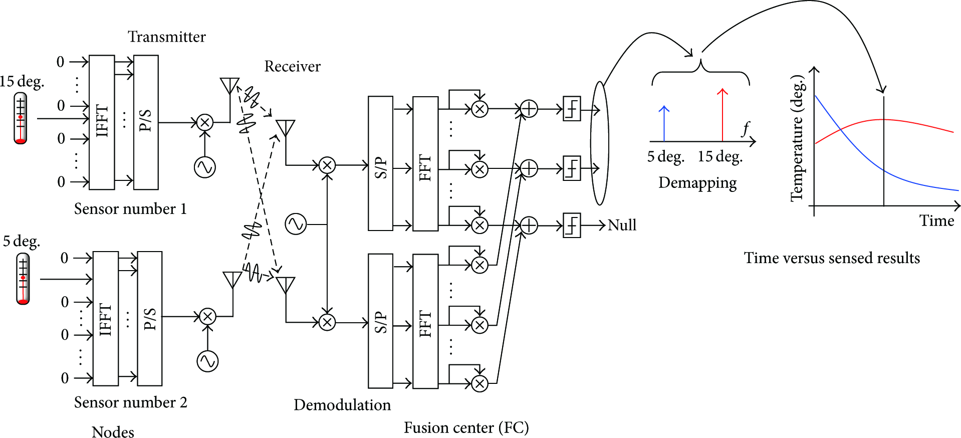
Overview of WC-SDC.
In FC, after downconversion by the local oscillator, the frequency components of the received signal are detected by FFT. If the receiver is equipped with the multiple receiving antenna, the process of detecting the frequency components is performed in parallel. The square of frequency components is calculated for obtaining the power of each signal. After that, the powers of frequency components from all the receiving antennas are combined, together. The IFFT point number selected by the transmitter is recognized by comparing each power of frequency component with the certain threshold in FC. Therefore, the threshold setting is required and the detail setting method is described in the later section. As a result, the FC can recognize the sensed data from the detected point number in accordance with the projection rule between the point number and the sensed data. After FC continuously detects the sensed data, it recognizes that the detected results are composed of multiple data sequences. The data tracking is used for decomposing each data sequence.
3. Data Tracking of Kalman Filter
This paper decomposes each piece of sensed data from the frequency components with Kalman filter [8].
Kalman filter evaluates the time transition of each data and thus obtains the time-smoothest data sequence. The FC collects the data with the WC-SDC, and then it decomposes each data sequence by Kalman filter.
3.1. Model of Kalman Filter
Figure 3 shows the processing flow of the considered Kalman filter.

Processing flow of Kalman filter.
All the sensor nodes inform the FC about the sensed data, periodically, where the minimum time duration of the informing period is defined as slot. In FC, the sensed data are detected from the received signal by the decision threshold. In kth time slot, the sequence of detecting the sensed data is defined as
In kth time slot, the a priori estimated statement is


Next, the Kalman gain is derived for estimating the statement and defined as

The a posteriori covariance matrix is updated as follows:

From the obtained Kalman gain, the a posteriori statement,


3.2. Error Tracking
In Figure 4, when the two data sequences are near together or crossed each other, the two results of data tracking wrongly become one data sequence. It is error tracking. For avoiding the error tracking, we pay attention to the temporal continuity of slope in data sequence. We propose the following algorithm based on the temporal continuity of slope.
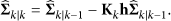
After Kalman filter, the estimated data sequence, In each time slot, before Kalman filtering, the FC counts the kinds of sensed data which the FC detects from the frequency component, where the number of frequency components is After Kalman filter, the FC also counts the kinds of sensed data, where the number of pieces of sensed data is If Average slope: the FC evaluates the average slope before TP, where Kalman filter for second rank: in (2), the selection criterion is changed from the minimum distances between the detected data The FC counts the number of events to merge the detected data, where the number of events is q. If Recovering process of error tracking: the FC can obtain the two average slopes after TP as follows:
If the following equation in lth where


Error tracking.
As a result, the similarity between the averaged slopes of the prior TP and the a posteriori TP is maintained. Each data sequence is decomposed and thus the error tracking is decompensated. However, the proposed solution of error tracking causes the processing delay. Therefore, the error tracking cannot be removed in real time. Since the amount of processing delay depends on the size of memory, L, we consider that the adequate L is clarified in the numerical results.
4. Counter Measure of Frequency Offset
Figure 5 shows the detected frequency spectra of one carrier after FFT in FC, where the frequency offset does not occur and does occur, respectively. If the decision threshold (A) is selected, the components of side lobe are detected and thus the image data appear. On the other hand, if the decision threshold (B) is selected, these do not appear. However, when the fluctuation of signal power occurs by the multipath fading, the misdetection of desired spectrum occurs. Therefore, the adequate threshold for detecting the desired spectrum but not detecting the noisy components should be constructed. In this paper, the construction of decision threshold is considered in computer simulation.

Impact of frequency offset in WC-SDC.
If the multiple receiving antenna is available, the receiving diversity gain can be obtained [10]. In the receiving diversity, when the received signals from antenna are combined together or adaptively selected, the probability of obtaining the large power of received signal is enlarged. The receiving diversity gain is defined as its enlargement and increased as the number of antennas becomes large. For obtaining full diversity gain, the matched filter to the channel transfer function between transmitter and receiver is necessary [11], where the channel transfer function is derived by the Fourier transform of the channel time impulse response. For simplicity, our proposed system does not use the matched filter. Instead, the square components of detected signal are combined. Even if the obtained diversity gain is not full, it is large enough for the fusion center to avoid the misdetection of the desired spectrum. Therefore, the large margin of decision threshold is available for avoiding the detection of the noisy components caused by frequency offset. As a result, the high quality detection is achieved. As previously described, Figure 2 shows the process flow of our proposed system in FC.
5. Measurement Environment
This research constructs the evaluation system integrating the indoor experiment with the computer simulation.
In indoor experiment, the five temperature monitors (EM-SD) are used as the sensor nodes, where these monitors records the sensed data in flush memory. Figure 6 shows the location of five monitors in indoor environment. In each sensor, the temperature is detected every 20 seconds and then the sensed data is recorded in the flush memory. The measurement time is 30 minutes and thus the number of pieces of the obtained data in each sensor is 90, where the record format is CSV. In 1 minute after the start, the oil heater is worked for enlarging the temperature. The location of oil heater is shown in Figure 6.

Measurement environment.
The wireless communication environment is simulated by computer. In the computer simulation, each sensor node transmits the recorded data to the fusion center through the wireless communication channel. For the WC-SDC, the number of FFT points is 512 and the dynamic range of temperature is limited from 0 degrees to 51.2 degrees. The quantization level is 0.1 degrees. The channel from each node to FC is modeled by independent Rayleigh fading. The frequency flat fading is assumed because each sensor uses one subcarrier and the constructed signal is so narrow that the fading coefficient is constant for one subcarrier. For every 20 seconds, the independent fading occurs. For detecting the frequency component, the threshold for achieving
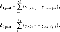
Decomposing results of data collected by WC-SDC.
The initial parameters of Kalman filter are used as follows:

We assume the real time separation of data sequence. Therefore, even when the proposed technique can detect the error tracking, it cannot compensate the error tracking in past data.
6. Numerical Results
6.1. Error Tracking and Solution
Figure 7(a) shows the log data of sensed temperature in each sensor. We can see the temperature of node #2 is dramatically increased after about 100 seconds. This is because node #2 is near the oil heater so oil heater is worked after 1 minute from the start of examination. In addition, all the sensed data have the increasing tendency because the oil heater spreads the heated air over the room. Figures 7(b) to 7(e) show the tracking results, where the signal to noise power ratio (SNR) is 40 dB and the number of receiving antennas is two. “Conventional” and “proposed” mean the results without the proposed solution for the error tracking and with it, respectively. In the proposed method, as shown in Figures 7(c) to 7(e)
In Figure 7(b), the error tracking between nodes #3 and #4 occurs after 750 seconds. From the original data as shown in Figure 7(a), the temperature difference between two data sequences is small. Kalman filter uses the minimum difference of temperature transition as the criterion of tracking. After cross point, the Kalman filter easily traces one sequence after crossover point. Therefore, the error tracking occurs. On the other hand, in proposed technique, from Figures 7(c), 7(d), and 7(e), the error tracking is avoidable. However, around 750 sec, the two results of #3 and #4 wrongly become the same data sequence. When
For evaluating the fidelity of tracking results to the original data, the mean absolute error (MAE) is defined as follows:

Since the proposed solution with
6.2. Impact of Frequency Offset and Solution
Figure 8 shows the detected results in the WC-SDC when the normalized frequency offset is 0.05. Note that Kalman filtering is not performed in these results. In Figures 8(a) and 8(b), the margins of decision threshold, α, are 1 and 7, respectively. In

Decomposing results of data collected by WC-SDC (margin of decision threshold).
Figures 9 and 10 show the performance between the margin of decision threshold, α, and MAE, where the numbers of receiving antennas are 2 and 4, respectively. “Ideal” indicates that after all the sensors perfectly inform the sensed data to the FC without any distortion through the wireless channel, the Kalman filter is performed. For comparison, the MAE of “ideal” is constant for any α.

Performance between margin α and MAE (number of receiving antennas is 2).
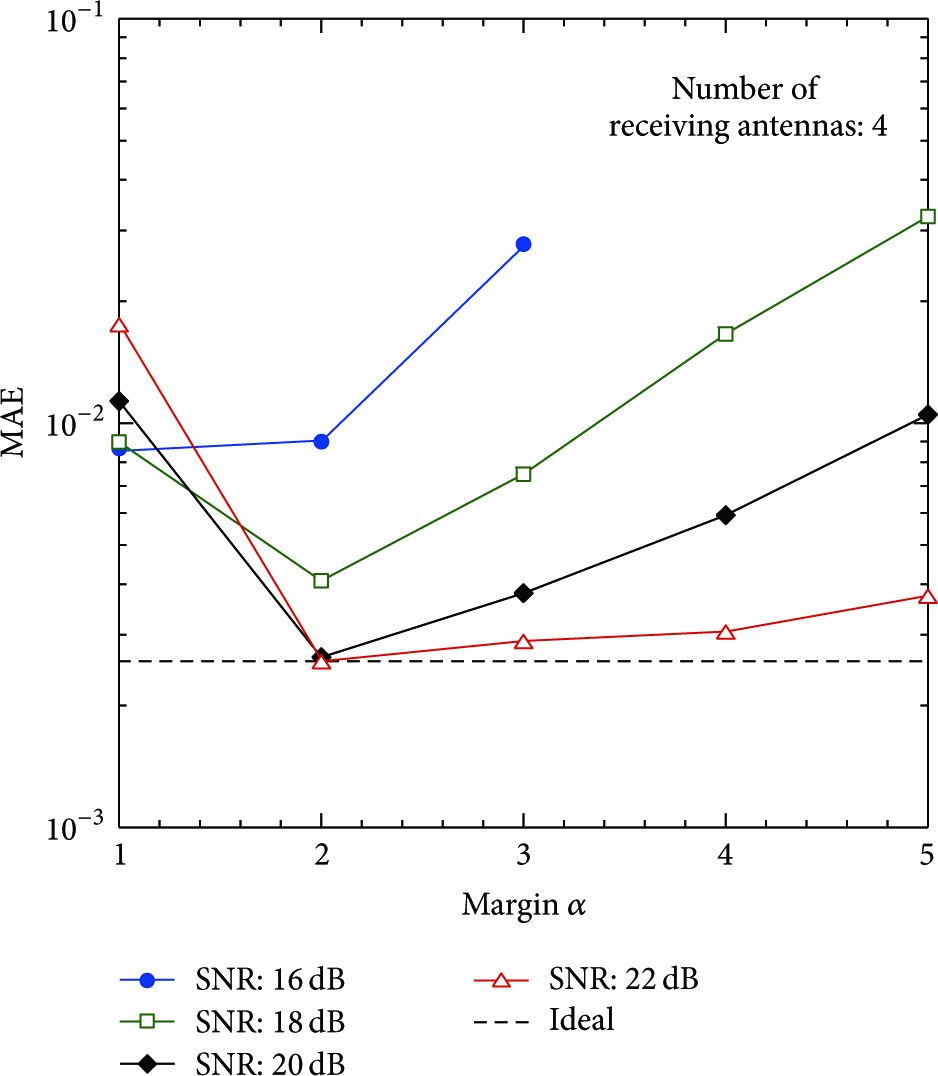
Performance between margin α and MAE (number of receiving antennas is 4).

Performance between normalized frequency offset and MAE.
In Figure 9, SNRs have 20 dB, 25 dB, 30 dB, 35 dB, and 40 dB, respectively. From this figure, each performance takes the concave tendency for the margin threshold, α. When α is small, the threshold is set under the noisy components caused by frequency offset. On the other hand, when α is large, the margin for the desired components is small and thus the misdetection, where the sensor cannot detect the sensed data, occurs. Therefore, α is adaptively adjusted for minimizing MAE. Even if the optimization of α and the large SNR are obtained, the MAE is not as large as that of “ideal.” As SNR becomes larger, not only the desired signal power but also the power of noisy components caused by frequency offset becomes larger. Therefore, the sensitivity to desired component is not improved when the required margin α becomes large.
In Figure 10, when SNRs are 20 and 22 dB, the best MAE of proposed technique is as large as that of “ideal.” As the number of antennas becomes large, not only the reduction of the required SNR but also the good MAE performance is achieved. Since the receiving diversity gain is increased due to increasing the number of receiving antennas, the power of desired components is maintained at high level but the noisy component caused by frequency offset is not enlarged. Therefore, even when the decision threshold is large for avoiding the detection of noisy components, the misdetection is avoidable. Since the proposed technique with
Figure 11 shows the performance between the normalized frequency offset and MAE, where “conventional” and “proposed” are the results with single antenna and SNR = 50 dB and four antennas and SNR = 20 dB, respectively. The proposed technique uses
7. Conclusions
This paper evaluated the accuracy of data separation by Kalman filter in the wireless sensor networks for the simultaneous multidata collection. For avoiding the error tracking, where the two data sequences wrongly become one data sequence, we propose the algorithm for evaluating the slope of the continuity of the sensed data. For compensating the degrading of the tracking performance by the frequency offset, we propose the margin of decision threshold and the receiving diversity. From the numerical results, even when the frequency offset occurs, our proposed technique achieves the highly accurate data decomposition.
It is important future work that a WC-SDC is applied to various kinds of sensors, such as pressure, motion sensor, and seismic intensity. In addition, for evaluating the performance of real time or processing delay, the implementations of the WC-SDC and the Kalman filter with the proposed method are necessary and also important future work.
Footnotes
Conflict of Interests
The authors declare that there is no conflict of interests regarding the publication of this paper.
Acknowledgment
A part of this research project is sponsored by Ministry of Internal Affairs and Communications in Japan under the project name of SCOPE (135003005).