
Abstract
In IEEE 802.11 WLANs, many rate adaptation studies have proposed rate adaptation schemes to differentiate channel-related loss and collision loss in order to enhance WLAN performance. Most of these studies focus on rate adaptation schemes on the client side when many clients transmit uplink traffic to an access point (AP). However, considering the high proportion of downlink traffic in WLANs, rate adaptation on the AP side has a greater impact on WLAN performance and is more influenced by the downlink traffic on neighboring APs. In addition, considering that many APs are deployed in the real world, some APs use the same channel and are hidden from each other. In this paper, we first analyze the impact of hidden nodes on the rate adaptation scheme. We then propose a new rate adaptation scheme, called Hidden node Effect aware Rate Adaptation (HERA). HERA optimizes the RTS exchange by utilizing RTS transmission success/failure and makes rate decrease decisions based on frame error rate (FER) in order to enhance WLAN performance. We evaluate the performance of HERA through extensive simulation, comparing it with other well-known rate adaptation schemes. Simulation results show that HERA outperforms other rate adaptation schemes by up to 161% in terms of downlink throughput in hidden node environments.
1. Introduction
Recently, as the Internet of Things (IoT) has become one of the hottest topics in information and communications technology, wireless sensor networks (WSNs) are also getting more attention. Traditionally, the low-power wireless radio technology such as a Zigbee has been widely used for WSNs. However, with the advancement of radio technologies and the advent of various IoT applications utilizing sensor data, various radio technologies such as Bluetooth, WiFi, and WiMax are applied for WSNs. In particular, because of the increase in smart devices such as smartphones and tablet PCs with various sensors and WiFi interfaces, WiFi has become one of the important radio technologies for WSNs.
WiFi is a local area wireless technology based on IEEE 802.11 WLAN standard [1]. This standard defines the medium access control (MAC) and several physical (PHY) layer specifications. At MAC layer, both distributed coordination function (DCF) and point coordination function (PCF) are defined as medium access methods. However, a DCF based on carrier sense multiple access with collision avoidance is used in most of IEEE 802.11 devices as the fundamental access method.
At the PHY layer, multiple transmission rates that use different modulation and coding schemes (MCS) are defined in order to utilize wireless resources efficiently according to the channel condition. Wireless channel conditions vary dynamically because of interference, channel fading, device mobility, and obstructions. Therefore, a rate adaptation scheme that changes the transmission rate in response to the varying channel condition is needed in order to maximize the channel efficiency. While the IEEE 802.11 standard does not specify any rate adaptation scheme or protocol, many rate adaptation schemes have been proposed in the literature [2–19]. The goal of these rate adaptation schemes is to dynamically change to the transmission rate that provides maximum throughput. Although many rate adaptation schemes utilize channel information such as the signal to noise ratio (SNR) and received signal strength indicator (RSSI), statistics-based approaches that utilize only transmission results are the most widely used ones in commercial 802.11 products because of their simplicity and hardware independence.
In WLANs, packet loss can occur because of not only channel condition but also collision. Statistics-based rate adaptation schemes can degrade WLAN performance significantly by lowering the transmission rate unnecessarily due to packet losses caused by collision. In order to alleviate this problem, several rate adaptation algorithms with loss differentiation scheme have been proposed [5–11]. Some of these rate adaptation schemes use the RTS/CTS exchange to differentiate frame losses caused by collision. In [2], a “rate avalanche” effect was introduced that could significantly degrade the performance of heavily loaded networks with many clients. Furthermore, the authors showed that this can be alleviated by actively using the RTS/CTS exchange when the rate adaptation scheme detects the rate avalanche effect.
Most of these studies mainly focus on an environment where many clients are associated with one AP and all the clients continuously transmit uplink traffic (from client to AP). Hence, they modify the client side rate adaptation scheme and attempt to enhance the single/aggregated uplink throughput. However, the proportion of downlink traffic (from AP to client) is much higher than uplink traffic. Some studies have reported the presence of the asymmetric patterns with around 80% of total traffic consisting of downlink traffic [20]. This means that AP rate adaptation scheme has a significant impact on the WLAN performance even though many clients are associated with the AP. Furthermore, the rate adaptation scheme on the AP side is significantly influenced by the downlink traffic of neighboring APs. Considering the environments in which many APs are deployed, some APs use the same channel and are hidden from each other. When one AP sends traffic to the client affected by a hidden AP, the throughput of the AP can be degraded drastically because of packet losses caused by collision.
In this study, we observe that the performance of existing rate adaptation schemes can be degraded when hidden APs exist. We analyze the cause of the performance reduction in the hidden AP scenario and design a new hidden node effect-aware rate adaptation (HERA) scheme that addresses the effects of hidden APs. The proposed scheme does not require modification of the standard MAC protocol to notify wireless channel information between sender and receiver. Furthermore, it is easy to apply to the real environment because it requires only the modification of the rate adaptation scheme loaded in the AP. While most previous proposals focus on the performance of uplink traffic, we focus on enhancing the downlink performance. As the proportion of downlink traffic is much greater than uplink traffic, an AP side rate adaptation scheme makes a greater contribution to real WLAN performance than a client side scheme.
The rest of this paper is organized as follows. First, we review related work in Section 2. In Section 3, we analyze the effect of hidden nodes on the rate adaptation scheme. In Section 4, we describe the design of the HERA. Performance evaluation results and analysis are presented in Section 5. Finally, in Section 6, we conclude the paper.
2. Related Work
As mentioned above, many rate adaptation schemes for IEEE 802.11 WLAN have been proposed in the literature. They can be broadly classified into two approaches based on the information used for rate adaptation. One is the statistics-based approach, which predicts channel condition using transmission statistics such as consecutive frame success/fail, frame error rate (FER), and average throughput. These approaches increase/decrease the transmission rate after collecting sufficient statistics. The other approach is the channel quality-based approach, which predicts the channel condition using the information from the PHY layer such as RSSI and SNR.
2.1. Statistics-Based Approach
Automatic rate fallback (ARF) [3] is a widely adopted and well-known rate adaptation scheme. This scheme decides whether to increase or decrease the data rate based on consecutive transmission success/failures and a timer. The data rate is decreased when two consecutive transmission attempts fail and is increased when ten consecutive transmission attempts succeed. The timer is used to increase the data rate after the current data rate has been used for certain period. The timer can be implemented as a time-based or packet-based timer. If the data rate increases and the next transmission attempt fails, it returns to the previous rate immediately. Adaptive ARF (AARF) [4] was proposed in order to reduce unnecessary data rate increase attempt. It doubles the number of consecutive transmission successes required to increase the data rate if the first transmission attempt at the higher rate fails.
As mentioned above, packet loss can occur not only because of channel condition but also because of collision. Because ARF and AARF cannot differentiate channel-related loss and collision loss, they decrease the data rate unnecessarily due to frame losses caused by collision. This leads to WLAN performance degradation.
To solve this problem, [5] proposed the collision-aware rate adaptation (CARA) scheme, which uses the RTS/CTS exchange mechanism in order to differentiate the frame losses caused by collision. If data transmission failure occurs without RTS/CTS, it uses the RTS/CTS mechanism at the next data transmission. If the next data frame with an RTS/CTS exchange fails, the data rate is decreased. Otherwise, it regards the previous frame loss as a collision loss and does not change the data rate. However, because it mainly considers collision caused by multi-client contention in a single collision domain, it may suffer from an RTS/CTS oscillation, where the RTS/CTS exchange is continuously turned on and off when a hidden node exists.
The robust rate adaptation algorithm (RRAA) [6] uses the FER to decide whether to increase or decrease the data rate. It calculates the FER by counting the number of transmission failures within an observation window. If the FER is greater/lower than a predetermined threshold, it decreases/increases the data rate. The threshold value and observation window size are predetermined according to each PHY rate. In addition, RRAA uses adaptive RTS (A-RTS) scheme for loss differentiation similarly to CARA. Unlike CARA, RRAA can handle collision losses caused by hidden nodes. However, in some cases, it increases the RTS/CTS overhead because of unnecessary usage of RTS/CTS exchange.
Researchers in [7–9] proposed loss differentiation mechanisms without RTS/CTS exchange. In [7], researchers proposed the background traffic-aware rate adaption scheme (BEWARE) that uses a mathematical model to calculate the expected transmission time based on wireless channel and background traffic condition. Similarly, researchers in [8] proposed a rate adaptation scheme which utilizes channel busy time to identify congestion-related losses. In [9], researchers proposed the effective rate adaptation (ERA) scheme which sends fragmented short data frame instead of RTS/CTS exchange after transmission failure to differentiate collision loss. However, these schemes can suffer from the collision losses caused by hidden node.
Researchers in [10, 11] proposed a loss differentiation mechanism that uses explicit notification in the MAC frame. They added an extra frame and fields to indicate the cause of losses. However, this requires modification of the IEEE 802.11 standard and thus is hard to deploy in the real-world.
Most of these proposals for loss differentiation mechanisms in rate adaptation schemes mainly consider the environment where many clients are associated with one AP that continuously transmits uplink traffic. However, in general, proportion of downlink traffic is much higher than uplink traffic even if many clients are associated with one AP. Considering these WLAN traffic characteristics, the rate adaptation scheme on the AP side is more influenced by the downlink traffic of neighboring APs than the uplink traffic of its associated clients.
In the statistics-based category, some researchers proposed rate adaptation schemes specialized for specific applications. In [12], a rate adaptation was proposed with a fast decrease scheme in order to improve the quality of service of VoIP traffic. Further, [13] proposed a rate adaptation scheme for industrial applications for which frame loss and timing are critical. It uses the lowest rate for retransmission in order to ensure reliable transmission for these industrial applications.
2.2. Channel Quality-Based Approaches
These approaches use wireless signal strength information, such as RSSI and SNR, to decide the data rate [14–19]. They choose the data rate using predetermined table that maps the signal strength to the data rate. The advantage of these approaches is that they can immediately change the data rate in response to channel variations. However, they depend on the accuracy of the channel information from the PHY layer. These approaches also require modification of the IEEE 802.11 standard to notify the sender of exact receiver side signal quality. Otherwise, they suffer from the asymmetric nature of wireless channels if they only use the signal strength of the ACK frame received at the sender.
3. Effect of Hidden Nodes on Rate Adaptation Schemes
In this section, we first analyze the impact of hidden nodes on the rate adaptation scheme. For this, we evaluated the performance of well-known rate adaptation schemes (ARF, AARF, CARA, and RRAA) using ns-3 simulation [21]. From the simulation results, we observed that performance degrades for each of the schemes for various cases. In addition, we analyzed why these rate adaptation schemes do not perform well in the hidden node scenario. This investigation motivated the design of a new rate adaptation scheme that addresses the effect of hidden nodes and inspired the design principal of this proposed rate adaptation scheme.
3.1. Elementary Topology
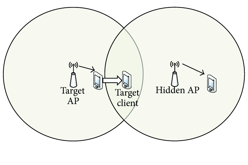
Figure 1 shows the elementary topology used in this paper. Clients A, B, and C are associated with AP 1 (the target AP) and client D is associated with AP 2 (the hidden AP). Each circle indicates the maximum transmission range at the lowest data rate. AP 2 is placed far away from AP 1 such that the APs are hidden from each other.

Hidden AP topology.
When the target AP sends traffic to the associated client, the effect of the hidden node varies according to the location of the client. When the target AP sends traffic to client C, there is little effect from the hidden AP. However, when the target AP sends traffic to client B or C, the performance of the downlink traffic can be degraded because of the hidden node.
First, let us consider the case of client A, which is in the maximum transmission range of the hidden AP. If the hidden AP starts transmission before the target AP's transmission, the radio interface of client A switches to RX state because of hidden AP's transmission. This causes the target AP's transmission to the client A to fail. If the hidden AP generates saturated traffic, the target AP will experience transmission failure with a very high probability. We refer to this case as collision effect of hidden nodes in this paper. If the rate adaptation scheme of the target AP cannot distinguish losses caused by collision and losses caused by channel error, it decreases the data rate unnecessarily and achieves poor performance. The CARA and RRAA rate adaptation schemes differentiate collision losses using the RTS/CTS mechanism. Both of them use the RTS/CTS mechanism after data frame failure without RTS.
Second, let us consider the case of client B, which is out of the maximum transmission range of the hidden AP but near the edge of the maximum transmission range. In this case, the radio interface of client B does not switch to the RX state because of the hidden AP's transmission. However, when the target AP sends a packet to client B, the transmission signal from the hidden AP acts as interference with respect to client B. Because this interference decreases the signal to interference-plus-noise ratio (SINR) of a frame transmitted by the target AP, the frame can fail. We refer to this case as the interference effect of hidden nodes in this paper. In the case of frame losses caused by interference effect of a hidden AP, although the target AP uses the RTS/CTS exchange, it has no effect because the hidden AP cannot receive client B's CTS frame. Therefore, in this case, the use of the RTS/CTS mechanism after frame loss only causes unnecessary overhead.
3.2. Performance of RAAs with Hidden AP
As described above, the effect of a hidden AP can vary according to location of the client. In order to evaluate the performance of the well-known rate adaptation schemes and analyze their behavior in the hidden node scenario, we performed simulation using ns-3. The following parameters were used in the simulation: IEEE 802.11a PHY, log distance propagation loss model, UDP flow, and 1400 byte packet. In addition, carrier sense range was set to the maximum transmission range of 6 Mbps (i.e., 120 m), which is the lowest transmission rate of the 802.11a PHY (6–54 Mbps).
The simulation topology is shown in Figure 2. The hidden AP is 150 m away from the target AP and two APs are hidden from each other. The client associated with the hidden AP is 20 m away from it to guarantee that the hidden AP can send traffic to the client using a 54 Mbps rate without losses. The hidden AP sends saturated traffic to the client. The target AP also sends saturated traffic to the target client. We measured the throughput of the target AP by changing the location of the target client in each simulation. Figure 3 plots the performance of each rate adaptation scheme according to the location of the client associated with the target AP. In addition, we plotted the performance of the ARF without a hidden AP in order to identify the effect of the hidden AP.
Experiment topology.

Performance of rate adaptation schemes according to client location.
When there is no hidden AP, the throughput starts to decrease at about 27 m away from the target AP. On the other hand, when a hidden AP exists, the throughput starts to decrease at about 17 m away from the target AP. This is caused by the interference effect of the hidden AP. At 31 m away from the target AP, the throughput is degraded significantly. This is caused by the collision effect of the hidden AP. As described in Section 3.1, the target AP experiences transmission failure with a very high probability because of collision effect of a hidden AP. In this case, CARA and RRAA (with loss differentiation scheme) outperform ARF and AARF by about 100%. On the other hand, in the range 21–29 m, ARF and AARF show better performance than CARA and RRAA. The client in this range experiences interference effect from the hidden AP. In this case, the RTS/CTS exchange in CARA and RRAA only incurs extra overhead. In addition, there is an additional performance loss due to the characteristics of their rate adaption algorithm.
In order to further explain the reason for performance degradation in the range 21–29 m, we performed the following simulation. We placed the client associated with the target AP at 25 m away from the AP and changed the traffic bandwidth of the hidden AP in each simulation. Other simulation environment parameters are the same as in the previous simulation. In Figure 4, we plot the performance of each rate adaptation scheme. In addition, we also plot the performance when the data rate of the target AP is fixed to 54 and 36 Mbps.

Performance of rate adaptation schemes versus hidden AP traffic bandwidth.
As shown in Figure 4, when the hidden traffic bandwidth is under 3 Mbps, fixing the data rate at 54 Mbps gives the best performance. However, when the hidden AP traffic bandwidth is higher than 4 Mbps, the performance of the 54 Mbps (fixed) decreases rapidly because of the loss caused by interference of hidden AP traffic. In particular, when hidden AP traffic bandwidth is higher than 20 Mbps, most frames transmitted at 54 Mbps are lost. On the other hand, a fixed data rate of 36 Mbps shows the best performance when the hidden AP traffic bandwidth is higher than 4 Mbps. This indicates that if the SINR decreases because of interference from the hidden AP, the client at a given location cannot receive a packet transmitted at 54 Mbps, but it can receive a packet transmitted at 36 Mbps. Therefore, as hidden AP traffic bandwidth increases, the performance of 54 Mbps (fixed) decreases rapidly. In this simulation environment, CARA and RRAA show lower performance than ARF and AARF. The reasons are as follows.
First, CARA attempts to increases the data rate to 48 Mbps from 36 Mbps after ten consecutive transmission successes at 36 Mbps. If the first transmission at 48 Mbps fails, it does not decrease data rate immediately (in contrast, ARF decreases data rate). It sends next frame at 48 Mbps again after the RTS exchange for loss differentiation. Therefore, it requires two frame losses and one RTS exchange in order to return to the previous rate. Therefore, CARA achieves lower performance than ARF scheme.
Second, in the case of RRAA, the performance reduction is caused by its rate decision strategy and RTS overhead. Let us assume that every frame transmitted with 48 Mbps will be lost. According to the values in [7], RRAA attempts to increase the data rate after 40 transmissions at 36 Mbps. After the rate increases to 48 Mbps, it requires nine transmission failures to return to 36 Mbps. However, RRAA experiences consecutive transmission failures at 48 Mbps rate, unlike CARA. Because the consecutive transmission failures incur an exponential backoff of the contention window, RRAA performance reduces more than CARA performance.
Lastly, AARF shows good performance when the hidden AP traffic bandwidth is higher than 15 Mbps. However, when the bandwidth is 3–14 Mbps, we observe that there is a throughput gap compared to 36 Mbps (fixed). The reason for this gap is a periodic loss pattern caused by the hidden AP. AARF requires two consecutive transmission failures to decrease the data rate. However, when hidden node traffic is not saturated, transmission failures and successes can be repeated according to an a transmission interval of hidden AP. In the worst case, ARF and AARF do not decrease the data rate even though the FER of the current rate is 50%. In the simulation, ARF and AARF frequently use a higher data rate than 36 Mbps.
In summary, we observe that existing rate adaptation schemes show a performance reduction in the hidden AP scenario. Furthermore, we analyze the reasons for the performance reductions of these schemes. In addition, we take into consideration these observations in the design of HERA in Section 4.
4. HERA Design
In this section, we describe the design of HERA, a hidden node effect-aware rate adaptation scheme for IEEE 802.11 based WLAN. HERA is derived from AARF, but it is designed to overcome the misbehavior of AARF in the hidden node scenario. From the observations in Section 3, we define the following design goals.
We aimed to optimize the RTS-/CTS-based loss differentiation scheme. Because AARF has no loss differentiation scheme, it can suffer from the collision effect of hidden nodes by decreasing the data rate due to collision. CARA and RRAA try to overcome this effect using the RTS/CTS exchange but, as shown in Section 3, they incur unnecessary overhead in certain cases. Therefore, the RTS-based loss differentiation scheme should be optimized in order to reduce unnecessary overhead. Furthermore, the RTS/CTS exchange should be utilized adaptively to reduce packet loss caused by hidden node problems. Rate decisions should consider the interference effect of hidden nodes. Because AARF is derived from ARF, it requires two consecutive transmission failures to decrease the data rate. As shown in Section 3, according to the traffic pattern of hidden node, AARF experiences periodic transmission failures. In this case, AARF may select a data rate which experiences frame losses with high probability. In the worst case, it may keep the rate although the FER of the current rate is 50%. We refer to this misbehavior as rate overselection.
To achieve the above design goals, HERA has following features.
Optimized RTS utilization scheme: HERA minimizes unnecessary overhead of the RTS-based loss differentiation scheme by utilizing RTS transmission success/failure. Further, it prevents RTS oscillation in the case of collision loss caused by hidden nodes. Rate decrease decision based on frame error rate: To detect rate overselection due to periodic frame loss, HERA adopts a rate decrease decision based on FER.
4.1. Optimized RTS Utilization Scheme
HERA utilizes the RTS/CTS exchange not only to differentiate between collision and channel error but also to avoid collision loss due to hidden nodes, which is the original purpose of the RTS/CTS exchange. The RTS utilization scheme used in CARA may repeatedly turn RTS on and off in hidden node environments. Therefore, HERA uses RTS window scheme similar to RRAA. However, unlike RRAA, HERA adjusts the RTS window and RTS counter using the statistics of RTS transmission success/failure.
To explain the optimized RTS utilization scheme of HERA, we first plot a transmission state transition diagram in Figure 5. When the MAC protocol data unit (MPDU) arrives from the upper layer, the transmission state transits to “Transmit RTS” or “Transmit Data” from “Wait for MPDU” depending on RTS_on. After transmitting the data/RTS, the transmission state is changed according to the reception result of the ACK/CTS. Algorithm 1 shows pseudocode for optimized RTS utilization scheme in each state transition described in Figure 5.
RTS_on = false, RTS_window = 0, RTS_counter = 0; RTS_succ_counter = (i) Receive ACK (1) (2) (3) (4) Increase transmission rate; (5) RTS_on = true; RTS_counter++; (6) (7) (8) (ii) ACK Timeout (9) (10) (11) RTS_window++; (12) RTS_counter = RTS_window; (13) (14) (15) Decrease transmission rate; (16) RTS_on = true; RTS_counter++; (17) (18) (19) (20) (iii) RTS Timeout (21) Freeze the contention window (22) RTS_succ_counter = 0; (23) (24) RTS_counter = RTS_window; (25) (iv) Receive CTS (26) RTS_counter (27) RTS_succ_counter++;

Transmission state diagram.
HERA activates the RTS exchange in the following cases: (1) the first transmission attempt after the rate increase, (2) data transmission failure without the RTS exchange, and (3) RTS frame failure. In each case, the rationale for the RTS activation and detailed procedure are as follows.
4.1.1. Case 1: First Transmission Attempt after Rate Increase
HERA activates RTS exchange for the first transmission attempt after a rate increase (Lines 3–5). When the first transmission attempt with the RTS exchange fails after a rate increase, the rate adaptation scheme decreases transmission rate immediately because it ensures that the failure is caused by channel error. However, this approach may induce overheads in the environments where there is no loss caused by collision. Because HERA is derived from AARF, the rate increase attempt is performed at a low frequency compared to ARF. Therefore, the overhead of the RTS exchange, which is activated after a rate increase, is similarly small.
4.1.2. Case 2: Data Transmission Failure without RTS Exchange
HERA activates the RTS exchange when the data transmission fails without an RTS exchange (Lines 9–13). In this case, the RTS window is increased and the RTS count is set to the size of RTS window. In the following transmissions, the RTS exchange is performed until the RTS counter reaches 0. After that, if transmission of the data frame without the RTS exchange succeeds, the RTS window is set to 0 and the RTS exchange is deactivated. However, if the transmission of the data frame without the RTS exchange fails, the RTS window is increased, and the RTS counter is set to the size of the increased RTS window. This window-based RTS utilization scheme can prevent RTS oscillation, which is repeatedly turning the RTS on and off. Furthermore, HERA optimizes the RTS exchange using the statistics of the RTS frame success/failure. As mentioned in Section 3, the RTS exchange helps the rate adaptation scheme differentiate between collision and channel error in the case of the collision effect of hidden nodes. However, in the case of the interference effect of hidden nodes, the RTS exchange only induces unnecessary overhead.
In the case of interference effect, most of the RTS transmissions succeed because the RTS frame is transmitted with the lowest rate and its frame size is small (20 bytes). However, in the case of collision effect, the RTS exchange can fail if the hidden node started the transmission before the RTS transmission. In particular, the RTS exchange can also fail with high probability when the hidden node generates saturated traffic. Therefore, RTS transmission failures can be used to distinguish collision and interference effects. From this observation, if the RTS exchange succeeds N
On the other hand, after deactivating the RTS-based loss differentiation, a client of the AP may move to a location where there is collision, or a hidden node may be changed to an active state from an inactive state. In order to consider this, HERA activates the RTS exchange if the rate decreases after deactivating the RTS-based loss differentiation (Lines 14–16). If RTS exchange fails at next transmission, the RTS_succ_counter is reset to 0, and the RTS-based loss differentiation is activated again.
4.1.3. Case 3: RTS Frame Failure
If the RTS exchange fails, the RTS counter is set to the size of the RTS window in order to use the RTS exchange actively. The rationale of this is as follows. High loss probability of the RTS frame means that (i) there is severe collision loss or (ii) the channel condition is poor. In the former case, the RTS exchange prevents frame losses due to collision. In the latter case, the RTS exchange can be used to probe the channel condition before data frame transmission.
In addition, if an AP disables exponential backoff of contention window in the case of RTS frame failure, this can prevent the AP from wasting time for channel access due to the collision caused by hidden node. On the other hand, when the collision is caused by contention with associate clients, this gives higher channel access priority to the AP. Considering the high proportion of downlink traffic in WLANs, WLAN performance can be enhanced by giving higher channel access priority to AP than clients. Because HERA is only applied on AP side, we disable exponential backoff of contention window in HERA when RTS frame fails.
However, disabling exponential backoff can be a modification of the IEEE 802.11 standard although it does not require additional frames or modification of frame field in the standard. Therefore, we separated our proposed rate adaptation scheme into HERA and HERA_EB. HERA_EB is HERA with disabling exponential backoff. In order to perform a fair comparison, we mainly compared HERA with other rate adaptation schemes. And, we will show that HERA_EB can achieve significant performance gain when collision loss caused by hidden node occurs frequently in Section 5.
4.2. Rate Decrease Decision Based on Frame Error Rate
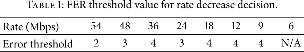
From the analysis in Section 3, AARF can suffer from rate overselection when the data frames are periodically lost because of the interference of hidden nodes. To this end, HERA adopts a FER-based rate decrease decision additionally by measuring the FER of the current rate. HERA uses the statistics of transmission result of last N frames to measure the FER of the current rate. If the number of failures of the last N frames exceeds threshold that is predetermined according to each PHY rate, HERA decreases the transmission rate. The threshold value is determined using equation below that considers the expected transmission time (ETT) of the data frame:

FER threshold value for rate decrease decision.
Success = 0; Failure = 0; recovery_mode = false; R is current transmission rate; (i) Receive ACK (1) Success++; Falure = 0; ewnd_counter++; (2) (3) (4) reset estimation window; (5) increase transmission rate (R++); (6) recovery_mode = true; ewnd_counter = 0; (7) (ii) ACK Timeout (8) (9) Falure++; Success = 0; ewnd_counter++; (10) (11) recovery_mode = false; (12) (13) N_err = the number of failures in estimation window (14) (15) decrease transmission rate (R− −); (16) (17) double Thres_succ; recovery_mode = false; (18) (19) Thres_succ = 10; (20) (21)
5. Performance Evaluation and Result Analysis
In this section, we evaluate the performance of HERA using the ns-3 simulator and compare it with well-known rate adaptation schemes such as ARF, AARF, CARA, and RRAA.
5.1. Simulation Setup
In the simulation, the following simulation parameters were used: 1400-byte packet size, IEEE 802.11a, constant speed propagation model, log distance propagation loss model, and UDP flow. Furthermore, the carrier sense threshold was set to the same maximum transmission range of 6 Mbps (i.e., 120 m). Each simulation was performed for 100 seconds and repeated five times with different seed values. The topology used in the simulation was the same as in Figure 2. Unless stated otherwise, the client (we refer to this client as the hidden client) connected to the hidden AP was 20 m away from the hidden AP and was unaffected by the transmission of the target AP. The hidden AP was 150 m away from the target AP. We measured the throughput of downlink traffic from the target AP to a client associated with it (we refer to this client as the target client). Except for the target AP, all nodes in the simulation use ARF as a default rate adaptation scheme. The number of consecutive successful attempts to increase the rate and the number of consecutive failures to decrease the rate in ARF are set to 10 and 2, respectively.
5.2. Performance Comparison according to Client Location
First, we evaluated the performance of rate adaptation schemes according to location of the target client in a hidden AP scenario. The hidden AP sends saturated traffic to the hidden client and the target AP also sends saturated traffic to the target client (i.e., the transmission queues of the two APs are never empty). Figure 6 plots the performance according to the location of the target client. We observe that the HERA outperforms other rate adaption schemes in all locations. When the target client is between 15 and 29 m away, it experiences an interference effect from the hidden AP. In this case, the RTS/CTS exchange for loss differentiation incurs unnecessary overhead. Therefore, AARF shows the best performance in this location. Although HERA utilizes RTS-based loss differentiation, it can minimize the RTS/CTS exchange using statistics about the RTS transmission failure/success. Therefore, HERA shows similar performance to AARF. On the other hand, CARA and RRAA show lower performance than ARF and AARF. The reason for this is described in Section 3.2.

Throughput comparison for rate adaptation schemes according to client location.
When the target client is more than 31 m away, it experiences a collision effect from the hidden AP. In this case, the target AP experiences transmission failure frequently due to collision. As described in Section 4, the RTS frames are also lost with a high probability when the hidden AP sends saturated traffic. Therefore, the performance of the target AP is sharply reduced. Nevertheless, HERA shows the best performance compared to other schemes. The reason for this is as follows. HERA resets the RTS counter to the RTS window size when RTS transmission fails. Therefore, most data frames are transmitted with the RTS/CTS exchange while RRAA and CARA turn off the RTS/CTS exchange frequently. More specifically, HERA outperforms ARF, AARF, CARA, and RRAA up to 161%, 147%, 39%, and 40%, respectively, when the client is 33 m away from the target AP. In addition, HERA_EB achieves about 40% higher throughput than HERA when collision loss due to hidden node occurs frequently. Because HERA_EB does not perform exponential backoff of contention window in the case of RTS failure, it can prevent the target AP from wasting time due to exponential backoff caused by collision loss. We observe that HERA_EB achieves up to 263%, 244%, 93%, and 96% higher throughput than ARF, AARF, CARA, and RRAA, respectively.
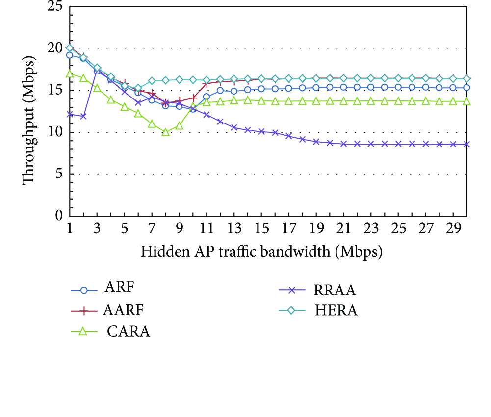
5.3. Performance Comparison with Varying Hidden AP Traffic Bandwidth in the Interference Scenario
We evaluated the performance of rate adaptation schemes under various hidden AP traffic bandwidths of hidden AP in the interference scenario. We placed the target client 25 m away from the target AP in the simulation. Figure 7 plots the performance of the rate adaption schemes with various hidden AP traffic bandwidths in this scenario. We observe that HERA shows better performance than the other schemes. In particular, CARA shows the worst performance when the hidden AP traffic bandwidth is 10 Mbps, and RRAA shows the worst performance when hidden AP traffic bandwidth is higher than 13 Mbps. The reason for the performance reduction of CARA and RRAA is described in Section 3.2. In particular, HERA shows good performance when the traffic bandwidth is 6–14 Mbps. As mentioned previously, depending on the traffic pattern of the hidden AP, the target AP may experience periodic transmission failure. This incurs rate overselection in ARF-based rate adaptation scheme. Because HERA prevents this by adopting a FER-based rate decreasing decision it achieves better performance compared to ARF and AARF. More specifically, HERA outperforms ARF, AARF, CARA, and RRAA by up to 28%, 22%, 69%, and 20%, respectively, when hidden AP traffic bandwidth is 10 Mbps. To further explain this, we plotted the distribution of the data rate used for each rate adaptation in Figure 8. As can be seen in this figure, most frames are transmitted at 36 Mbps, which provides the best throughput in this case.

Throughput comparison rate adaptation schemes for various hidden AP traffic bandwidths in the interference effect scenario.

Rate distribution for rate adaptation schemes in the case of interference when the traffic bandwidth is 10 Mbps.
We performed an additional simulation in different topology where interference effect occurs. In this simulation, the hidden AP and target client were located at 160 m and 35 m away from the target AP, respectively. The simulation results are shown in Figure 9. Because the target client is further away from the target AP than the previous simulation, average throughput is lower than the previous simulation. However, the patterns of results are similar to the previous simulation. From the simulation results, we observe that HERA shows better throughput than other schemes by transmitting most of frames at 24 Mbps, which provides the best throughput in this case.
Throughput comparison rate adaptation schemes for various hidden AP traffic bandwidths in the interference effect scenario.
5.4. Performance Comparison in the Collision Scenario
We evaluated the performance of the rate adaption schemes under various hidden AP traffic bandwidths in the collision scenario. In this simulation, we placed the hidden AP 130 m away from the target AP so that the hidden AP incurs collision effect on the target client. The target client was placed at 25 m away from target AP. The other simulation parameters were the same as in the previous simulation. Figure 10 plots the performance of the rate adaptation schemes in this simulation. We observe that HERA shows better performance than all other schemes except RRAA under a certain traffic bandwidth range (12–17 Mbps). As mentioned above, HERA uses RTS/CTS exchange actively when collision losses occur frequently so that it will be robust against collision loss caused by hidden node. On the other hands, RRAA shows good performance in certain cases because RRAA does not decrease the rate immediately upon consecutive frame losses. However, as observed in previous simulations, this mechanism can incur exponential backoff and degrade the WLAN performance significantly with respect to the AP's downlink throughput. In addition, we observe that HERA_EB achieves considerable performance gain under high hidden AP traffic bandwidth.
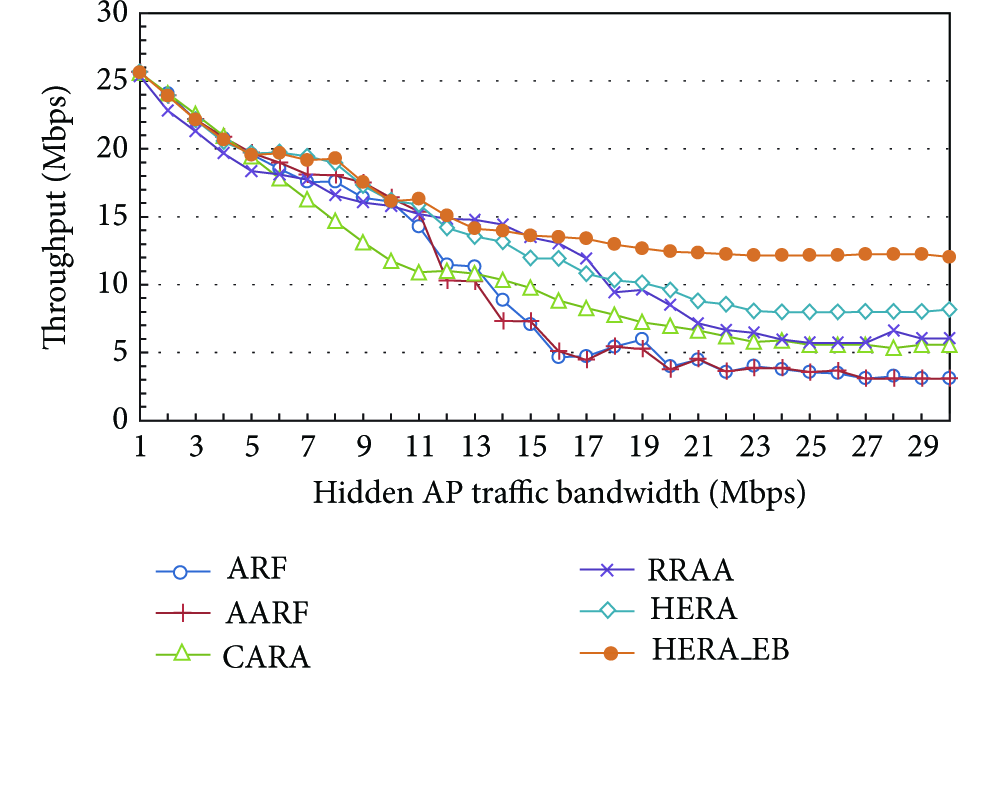
Performance of rate adaptation schemes versus hidden AP traffic bandwidth in the collision scenario.
Additionally, we performed a simulation with varying packet size in collision scenario because the overhead due to RTS/CTS exchange can vary depending on packet size. In the simulation, the hidden AP generates saturated traffic. The target AP generates saturated UDP traffic and we repeated the simulation with different UDP packet sizes from 200 bytes to 1400 bytes with step size of 200 bytes. Figure 11 plots the throughput according to packet size. As shown in this figure, as packet size gets bigger, HERA achieves more throughput gain compared to ARF and AARF that do not use RTS/CTS exchange.

Throughput comparison for rate adaptation schemes with varying packet size in the collision scenario.
We also evaluated the TCP performance in this collision scenario because the throughput of TCP flow is influenced by frame losses and transmission delay and it is the most widely used protocol for Internet applications. In this simulation, the target AP generates TCP traffic to the target client. In Figure 12, we plotted average TCP throughput of each rate adaptation when hidden AP traffic bandwidth is low, medium, and high. When hidden AP traffic bandwidth is low (1–10 Mbps), each rate adaptation scheme shows similar performance. However, when hidden AP traffic bandwidth is higher than 11 Mbps, HERA shows better TCP throughput than other schemes. From these results, we observed that HERA can achieve good performance in both UDP and TCP applications. In particular, when the hidden AP traffic bandwidth is high (21–30 Mbps), HERA achieves up to 146%, 142%, 38%, and 62% higher TCP throughput than ARF, AARF, CARA, and RRAA, respectively. In addition, we observe that HERA_EB can achieve significant throughput gain in collision scenario.

TCP throughput comparison for rate adaptation schemes versus hidden AP traffic bandwidth in the collision scenario.
5.5. Performance Comparison in the Environments Where Multiple Clients and Hidden APs Exist
Finally, we evaluated the performance in the environment where many clients are associated with the target AP. In this simulation, the hidden AP was located at 150 m away from the target AP and generated saturated traffic. Clients associated with the target AP were randomly located in a 10–40 m away from the target AP. In the repeated runs, the locations of clients were changed by using different seed values. The target AP generated TCP flows to all clients associated it.
We varied the number of clients in each simulation and the simulation results are shown in Figure 13. We measured aggregated TCP throughput for all clients and plotted average value over 10 simulation runs in this figure. As the number of clients increases, the performance is degraded by collision and performance anomaly effect [22] as shown in Figure 13. From the simulation results, we observed that HERA achieves better performance than other schemes in the environment where multiple clients exist. On average, throughput improvements of HERA over ARF, AARF, CARA, and RRAA are about 24%, 25%, 18%, and 29%, respectively.

TCP throughput comparison for rate adaptation schemes in multiple clients and one hidden AP scenario.
We also performed simulation in the environment where multiple hidden APs exist. In this simulation, 20 target clients were randomly placed in 10–40 m away from the target AP. Hidden APs were also randomly placed in 130–150 m away from the target AP. The target AP generated TCP flows to all clients associated with it. We varied the number of hidden APs in the simulation. In the repeated runs, the locations of hidden APs were changed. We plotted average aggregated TCP throughput over 10 simulation runs in Figure 14. As the number of hidden nodes increases, we observe that aggregated TCP throughput is reduced because of the increase of the number of target clients affected by hidden nodes. As shown in Figure 14, we observe that HERA also shows better throughput than other schemes in the environments where multiple hidden APs exist.

TCP throughput comparison for rate adaptation schemes according to the number of hidden APs.
In this experiment, we compared the throughput of each rate adaption scheme as a major performance index. Other performance indexes such as delay, jitter, and loss rate are also important in terms of network performance. However, in the rate adaptation schemes, low loss rate does not mean good performance in some cases (e.g., compare transmission at 54 Mbps with 10% loss rate with transmission at 6 Mbps with 0% loss rate). So, in this simulation, we measured end-to-end delay and jitter additionally to evaluate the performance better. Figures 15 and 16 show average delay and jitter, respectively. We observe that HERA shows lower delay and jitter than other schemes. The reason is that there is a high correlation between delay and throughput. In the simulation, most delay is caused by waiting time in target AP's transmission queue. Consequently, HERA which achieves better throughput than other schemes also shows lower delay than other schemes. In addition, HERA induces less variation of delay by preventing continuous losses caused by hidden nodes with RTS/CTS exchange and reducing the rate overselection with the FER-based rate decrease decision. Therefore, HERA shows a lower jitter than other schemes.
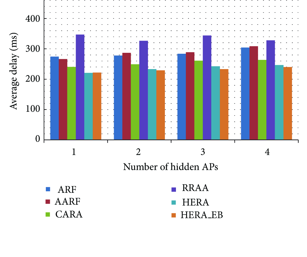
End-to-end delay comparison for rate adaptation schemes according to the number of hidden APs.

Jitter comparison for rate adaptation schemes according to the number of hidden APs.
In summary, from the simulation results in this section, we observe that HERA outperforms other schemes in a hidden node environment. In particular, when the collision effect of the hidden node occurs, HERA achieves up to 161% higher throughput than ARF. And when interference effect of the hidden node occurs, HERA achieves up to 69% higher throughput than CARA. In addition, we observe that HERA also achieves better performance than other schemes in the environment where multiple clients and hidden APs exist. Furthermore, we observe that HERA_EB achieves significant throughput gain where collision loss occurs frequently.
6. Conclusion and Future Work
In this paper, we analyzed the effect of hidden nodes on a rate adaptation scheme and proposed a new rate adaptation scheme called HERA. In order to address the performance reduction of existing schemes in hidden node environments, HERA optimizes RTS utilization by using RTS transmission statistics and reduces the rate overselection problem using a FER-based rate decrease decision. We evaluated HERA through extensive simulation and the results show that HERA outperforms well-known rate adaptation schemes (ARF, AARF, CARA, and RRAA) in hidden node environments.
In the future, we plan to implement the HERA scheme in a commercial AP device and build a real testbed to evaluate its performance in the real world.
Footnotes
Conflict of Interests
The authors declare that there is no conflict of interests regarding the publication of this paper.
Acknowledgments
This work was supported by the ICT R&D program of MSIP/IITP, Republic of Korea (13-911-05-001, Development of OpenFlow-Based Integrated Management System for Wired and Wireless Network). This research was supported by the MSIP (Ministry of Science, ICT, and Future Planning), Korea, under the ITRC (Information Technology Research Center) support program (NIPA-2014-H0301-14-1048) supervised by the NIPA (National IT Industry Promotion Agency).