
Abstract
The development of the Internet of Things (IoT) technologies has enabled smart objects to communicate with each other, and various IoT methods and techniques have appeared accordingly. At this point in time, there is a growing need for big data-based energy-IoT technology that can reduce energy consumption. However, despite the emergence of these technologies for IoT, there is still a lack of control systems to surmount the energy efficiency problem of hyperconnected IoT applications. In this paper, we attempt to reduce energy consumption by automatically controlling the communication between each device by establishing three different energy-IoT-based chains regarding the relationship of connections between devices.
1. Introduction
IoT technology will continue to develop rapidly, eventually leading to “the hyperconnected society,” in which all things will be connected through mobile and Internet communities and communicate with one another through the rapid development of the ICT [1, 2]. Approximately 50 billion mobile devices are currently connected to the Internet, and 500 billion devices, such as sensors, automobiles, smartphones, computers, buildings, and cities, are expected to be connected to the Internet [3]. According to the technological development of ICT, the scope of consolidation between human beings and things as well as things and things has expanded [4]. As this development proceeds, an intelligent Internet system will be embedded into the devices, and, therefore, the connection between devices will gain importance [5].
As IoT technology improves, the importance of the energy-IoT, which combines the IoT with energy, is growing as a new trend [6]. Technology will advance towards a hyperconnected energy-sharing community to build the energy Internet through the IoT to send and receive energy, and it will continue toward a hyperconnected society, which will expand the scope of connections between humans and machines as well as machines and machines [5, 7]. In this paper, we research the management and control of energy-efficient relationships between hyperconnected devices. Figure 1 shows a comparison between the current and future energy infrastructures. The current energy infrastructure is insufficient for efficient energy management and connectivity. In addition, the present system simply comprises on-off or dimming control based on information collected in two dimensions. For efficient energy management, a model must be developed for the relationship between hyperconnected IoT devices. This paper aims to illuminate the relationships between devices that are not as simple as on-off or dimming control as well as devices designed to optimize an energy strategy model grouped into three chains. We attempt to find a method to reduce energy consumption through the autonomous control of each device using the three energy-IoT-based chains.

Current system and future energy-IoT-based system.
2. Related Work
There have been many studies on energy-IoT technology in homes, buildings, cars, healthcare, and cities in terms of energy savings and user satisfaction. Huang et al. [9] proposed an IoT-based energy optimization model framework for realizing green IoT technology. The proposed system includes green deployment schemes for IoT through a hierarchical framework for deploying a network object and optimization model to achieve green IoT, and energy savings are demonstrated through an energy optimization algorithm. Chen et al. [10] proposed a wireless paradigm for green IoT using the time reversal (TR) technique. Their paper showed the advantage of the TR technique for energy harvesting and for improving energy efficiency (better battery life), privacy, and security of IoT devices. Sai and Mickle [11] presented the recent development in energy efficiency of wireless passive communication nodes and IoT applications. Their study showed the evolution of smart RFID-based wireless passive sensor node architecture to improve energy efficiency. Junqi et al. [12] proposed an energy-aware trust derivation scheme that demonstrated security and energy efficiency through the trust derivation scheme and game theoretic approach for IoT networks in a WSN environment. Huang et al. [13] proposed a system model with a service-merging method and collocating services to reduce the energy cost of communication. They demonstrated the service colocation problem of a multihop network and a single-hop network as well as an energy saving methodology through the proposed mechanism by using maximum weighted independent set (MWIS) algorithms. Similar to the abovementioned research, there are many studies on IoT technology-based systems and methods for improving energy efficiency and user satisfaction among various fields. In our paper, we propose a three-layer architecture for an energy-IoT-based building energy autonomous control system (BEACS) for energy savings and user satisfaction using the intelligent object energy chain (IOEC) mechanism.
3. Energy-IoT-Based Building Energy Autonomous Control System (BEACS)
3.1. Overview of Energy-IoT-Based BEACS
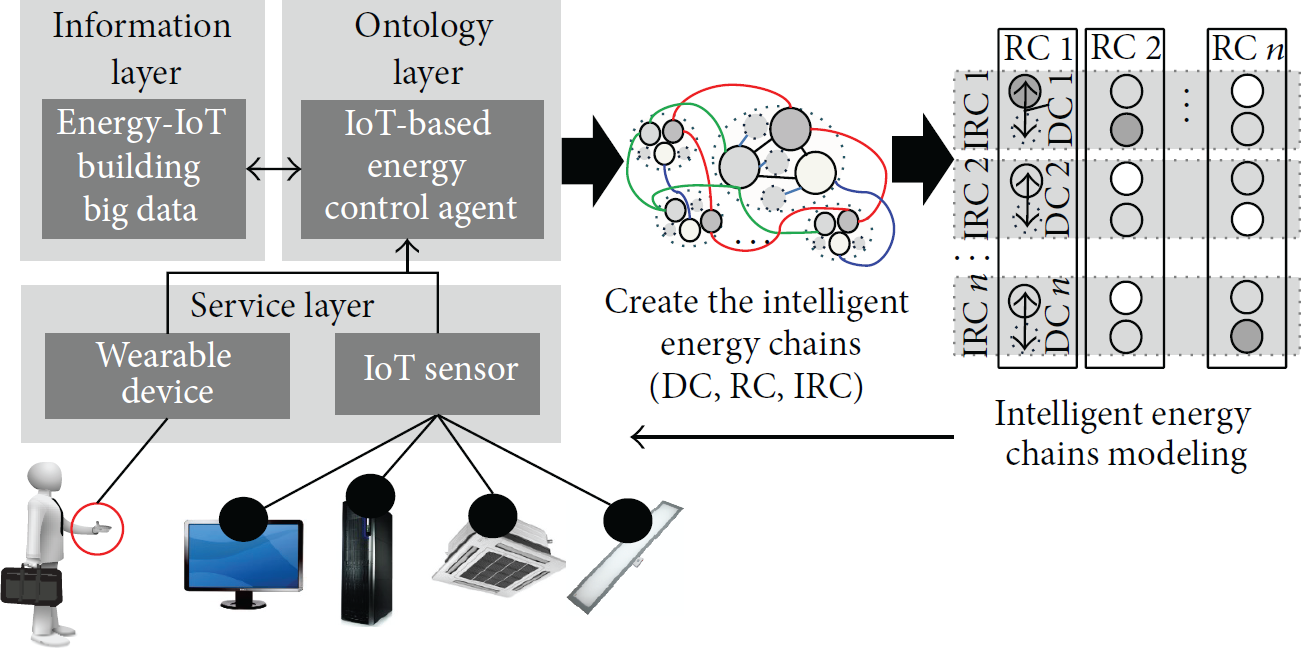
Figure 2 shows an overview of the IoT-based BEACS. The BEACS consists of an energy-IoT building big data (BBD), IoT-based energy control agent (IECA), and IoT devices (wearable devices, IoT sensors).
Overview of IoT-based BEACS.
The wearable devices and IoT sensors in the service layer gather information resources needed for the information layer. Wearable devices collect user information, and IoT sensors plugged into the devices collect the power information of the device and the surrounding environmental information. All data are stored in the BBD. The BBD recognizes the building information and determines the current user information and user behavior state. Further, IECA creates optimized intelligent energy chains and controls energy consumption effectively through the situational information collected by the big data information layer. The IECA creates three intelligent energy chains for energy savings and user satisfaction. The IECA then sends the optimized intelligent energy chains to the BBD.
The BEACS is divided into three layers: the information layer (BBD), ontology layer (IECA), and service layer (IoT sensors, wearable devices). We attempt to research the mechanism of optimized intelligent energy chains created through the IECA. Figure 3 shows the architecture of the energy-IoT-based BEACS. The following subsections describe the three layers.

Energy-IoT-based BEACS architecture.
3.2. Energy-IoT-Based BEACS Architecture
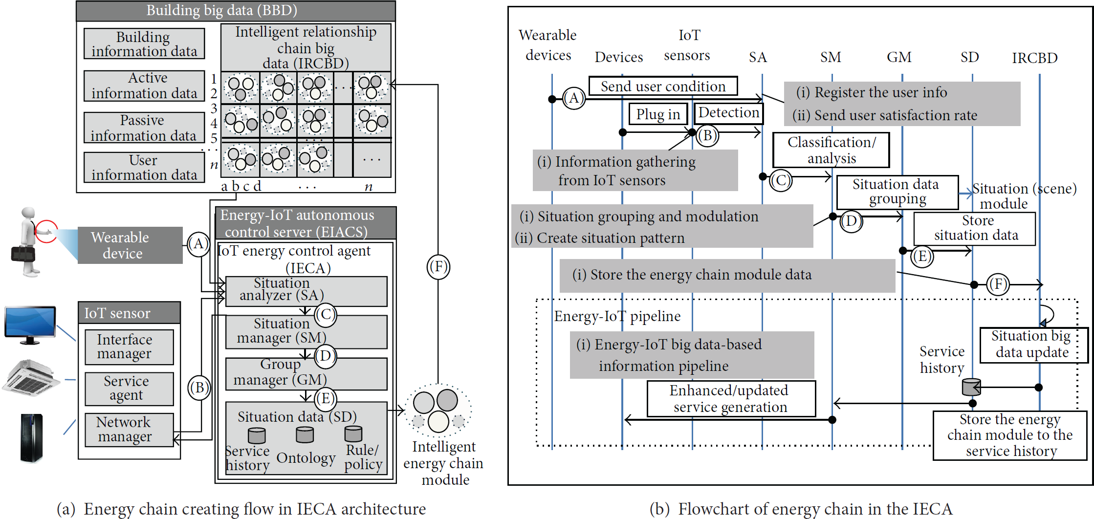
Information Layer. There are many types of information such as building information data, user data, device data, and user behavior data in the information layer. Building big data collected from end devices are stored and processed in the BBD. Wearable devices and IoT sensors gather the environment information and send the data to the BBD. Optimized intelligent energy chains created through the IECA are stored in the energy prediction control's intelligent relationship chain big data (IRCBD), and the enhanced/updated service information is sent to the IECA.
Ontology Layer. The ontology layer implements the key roles in the BEACS and classifies HVAC, lighting, and power analysis data coming from the information layer for the service forecast and energy control service. The energy-IoT autonomous control server (EIACS) in the ontology layer is composed of building context management (BCM), building data management (BDM), building data analyzer (BDA), and IoT energy control agent (IECA). The roles of BCM are management of environmental context and user profile, data gathering, and data storage. And BDM manages the lists of user service and the way of IoT application and provides necessary information. So, ontology layer is classified as HVAC, lighting, and power analysis coming from the information layer through the BDA. And the IECA establishes a relationship between the IoT devices based on the three chains to effectively control and save energy analysis [14]. We described the operation of IECA in “Control Scheme for the IoT Energy Control Agent (IECA)”.
Service Layer. The service layer is where the actual execution takes place; it provides a service through the energy savings and energy-efficient chain information created by the ontology layer. It is responsible for providing the service to the users and receiving control information from the IECA. It is composed of service design, service organization, energy-IoT service, and energy-IoT service resolution module; these are concerned with improving user satisfaction and energy saving.
3.3. Control Scheme for the IoT Energy Control Agent (IECA)
Figure 4 shows the three-chain model scheme with the device features. Figure 4(a) shows the energy chain creating flow, which creates the intelligent energy chain module, and Figure 4(b) shows the flowchart of the energy chain in the IECA. Figure 4(a) shows the architecture of the information layer (BBD), ontology layer (IECA), and service layer (IoT sensors, wearable devices). The IECA is divided into a situation analyzer (SA), situation manager (SM), group manager (GM), and situation database (SD). The concrete control operations are as follows:
User information is entered through the wearable devices. The user profile-based information is entered into the IECA as age, rank, hobbies, preferences, and so forth. Power, temperature, light intensity, humidity, and so forth are collected through the IoT sensors. The network manager of the IoT sensor then sends the information to the SA. The SA analyzes the situation based on the current user information and environment information. The SA then determines whether the input data recognizes the user's activities and whether changes in the information from the sensors and user devices represent a significant situation. Finally, the SA sends the processed information to the SM. The SM is a service decision manager. Before the energy chains are established, the SM decides what kind of service is suitable for the present situation. It then classifies the input data and converts the adaptive format for storage to the GM and the SD. Then, SM sends the energy chain information to the GM. The GM establishes groups according to the environment information gathered from the SM and then generates the intelligent energy chain modules (IECM). The GM stores the IRCM generated by the SD to the IRCBD in the information layer.
Energy chain control flow model scheme in IECA.
3.4. Three Intelligent Object Energy Chain (IOEC) Mechanisms
In this paper, we propose three device control chains to demonstrate the relationships among devices. Figures 5 and 6 show a schematic diagram of the three device chains.

Three Intelligent Object Energy Chains (IOEC).

Concept map of three hyperconnected IOEC.
Device Relation 1: Direct Chain (DC). A direct chain (DC) is the relationship in which devices are connected directly. Therefore, when the main device is turned off, the device directly connected to main device is automatically turned off. For example, when a PC connected directly to a monitor and other devices is turned off, the related devices (monitor, printer, scanner, etc.) are also turned off. For a sound booth and speaker connected in a conference room, if the sound booth is turned off, the speaker is automatically turned off.
Device Relation 2: Relationship Chain (RC). The relationship chain (RC) is a functional device group. For example, in Figure 7, PC 1/ 2/ 3…, Lighting 1/Lighting 2/Lighting 3…, HVAC 1/ 2…, and so forth are grouped into the same RCs. Devices in an RC share the control information through the RC.
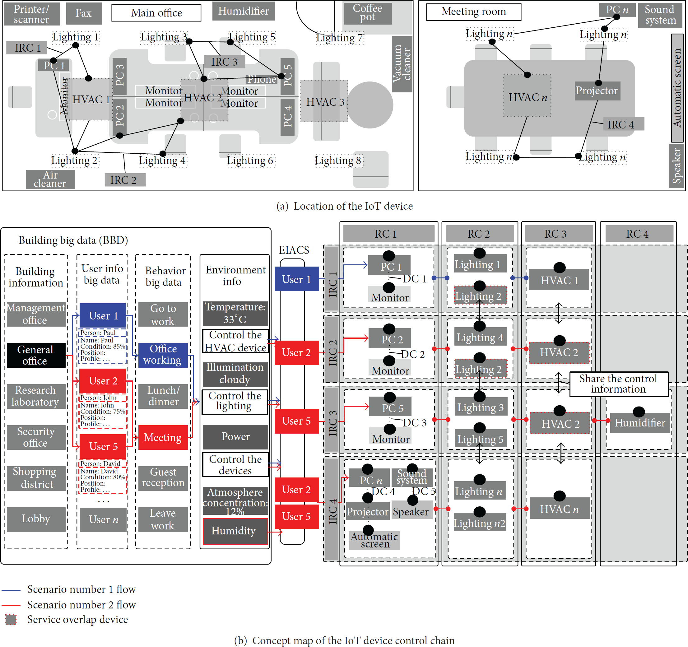
Locations of the IoT devices and concept map of the IoT device control chain.
Device Relation 3: Intelligent Relationship Chain (IRC). An intelligent relationship chain (IRC) is a device group that can be a big data-based intelligent control. An IRC is controlled intelligently by the association of all three chains through an environment analysis. All devices are plugged into IoT sensors, and related IoT devices are gathered as IRCs. For example, if PC 1, HVAC 1, and Lighting 1 are connected as IRC 1, when PC1 is turned on, the energy-IoT autonomous control server (EIACS) recognizes that User 1 has come into the office and controls the related devices (HVAC 1 and Lighting 1) of User 1.
4. Energy-IoT-Based Device Control Service Scenario
Figure 7 shows the scenarios for the creation of IRCs 1/2/3/4. Horizontal lines represent the IRCs, and vertical lines represent the RCs in Figure 7(b).
4.1. Scenario #1: Office Working Intelligent Relationship Chain (IRC 1)
Step 1 (information layer).
The BBD recognizes the building information and determines the current user information and user behavior state. In scenario #1 of Figure 7(b), the building information defines the general office building, and state of User 1 is “working in office.” The current environmental control information is transmitted to the EIACS.
Step 2 (ontology layer).
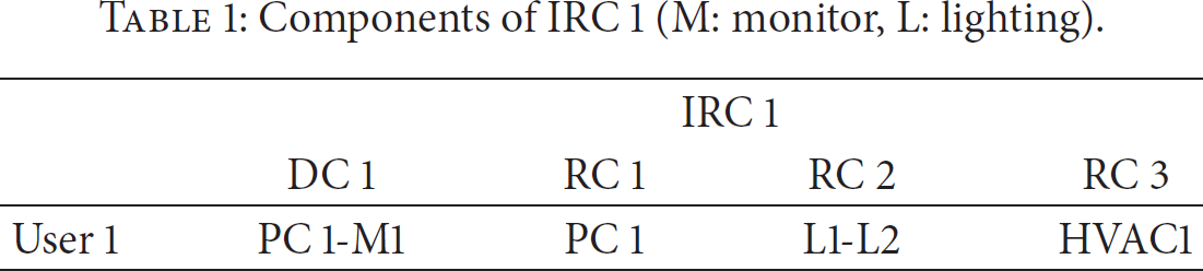
Table 1 shows the components of IRC 1. The EIFS selects the device and establishes the energy chain according to the current environmental information in Table 1. In Figure 7(b), IRC 1 is formed by the EIACS.
Components of IRC 1 (M: monitor, L: lighting).
Step 3 (service layer).
When User 1 turns on the PC, all devices connected to IRC 1 are controlled by the users and current information. The device chains are formed depending on the location/schedule/environment information. For example, if User 1 turns on PC 1, the monitor and scanner/printer are automatically turned on by the DC. The IoT sensor of PC 1 sends the PC control information (PC_ON) to the lighting connected by IRC 1, and then the lighting turns on. In addition, the HVAC also receives the PC-ON information. When the PC is turned off, all devices connected to IRC 1 also are controlled properly according to the environment. However, in the above picture, Lighting 2 is the service overlap device because Lighting 2 is in IRC 1 and IRC 2. The service overlay device is controlled by the state of other devices connected to the RC, because the control information of IRC 1 can affect IRC 2. Therefore, all devices connected to the device chains find locations with energy wastage and control the associated device.
4.2. Scenario #2: Meeting Intelligent Relationship Chain (IRCs 2/3/4)
Step 1 (information layer).
Users 2 and 5 have a meeting scheduled after lunch. First, the BBD recognizes the current building information and receives the current user information (User 2, User 5) and the users' behavior state (meeting). Then, the BBD sends the current information (temperature, humidity, light intensity, etc.) and control information to the EIACS.
Step 2 (ontology layer).
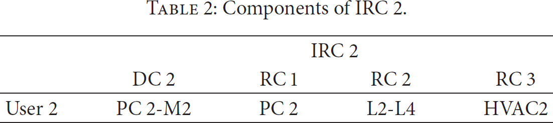
The EIACS utilizes the environment information to form the user-based energy device chains as listed in Tables 2, 3, and 4. The EIACS forms IRC 2, which connects the devices PC 2, Lighting 2/Lighting 4, HVAC 2, and so forth, associated with User 2. Moreover, the EIACS forms IRC 5, which connects devices PC 5, Lighting 3/Lighting 5, HVAC 2, Humidifier, and so forth, associated with User 5.
Components of IRC 2.
Components of IRC 3.

Components of IRC 4 (P: projector, AS: automatic screen, SS: sound system, and Sp: speaker).

Step 3 (service layer).
Lighting 2 is a service overlap device because it is in both IRC 1 and IRC 2. HAVC 2 is also a service overlap device because it is in both IRC 2 and IRC 3. A meeting is scheduled in the conference room after lunch. The main PC, projector, screen, sound system, and speaker are connected by a DC, and Lighting n/Lighting n2 and HVAC n are connected by IRC 4. When a user turns on PC n in the meeting room, the speakers and screen are automatically turned on. In addition, Lighting n and HVAC n begin operation after receiving the on/off information from PC n. Meanwhile, devices connected to IRC 2 and IRC 1 are dimmed or turned off to match the current situation.
4.3. Control Scenario of #1 and #2
Figure 8 shows the intelligent chain control graph of scenarios 1 and 2. As time passes, user behaviors change, and the devices are controlled based on user behavior. In Figures 7 and 8, when User 5 arrives at the office and turns on PC 5, all devices associated with PC 5 are turned on automatically. Because Monitor 5 is connected to PC 5 by a DC, it automatically turns on; because Lighting 3/Lighting 5 and HVAC 2 are connected to PC 5 by an IRC, they are also turned on. Moreover, when User 2 arrives at the office and turns on PC 2, all devices associated with PC 2 are turned on. However, because HVAC 2 overlaps between IRC2 and IRC3, it is a device whose service is duplicated. Service overlap devices are controlled by the service overlap control line; if User 2 turns off PC 2, HVAC 2 turns off automatically, but when HVAC 2 is turned off, it can affect IRC3 because HVAC 2 also belongs to IRC3. Table 5 shows the power consumption of lighting and HVAC according to light illumination and HVAC intensity. Table 6 shows the device control values according to the user behavior.
Power consumption according to illumination/intensity (excluding standby power) [8] “power consumption value is measured by the power monitoring system (PMS).”

Device control value according to user behavior.

L2
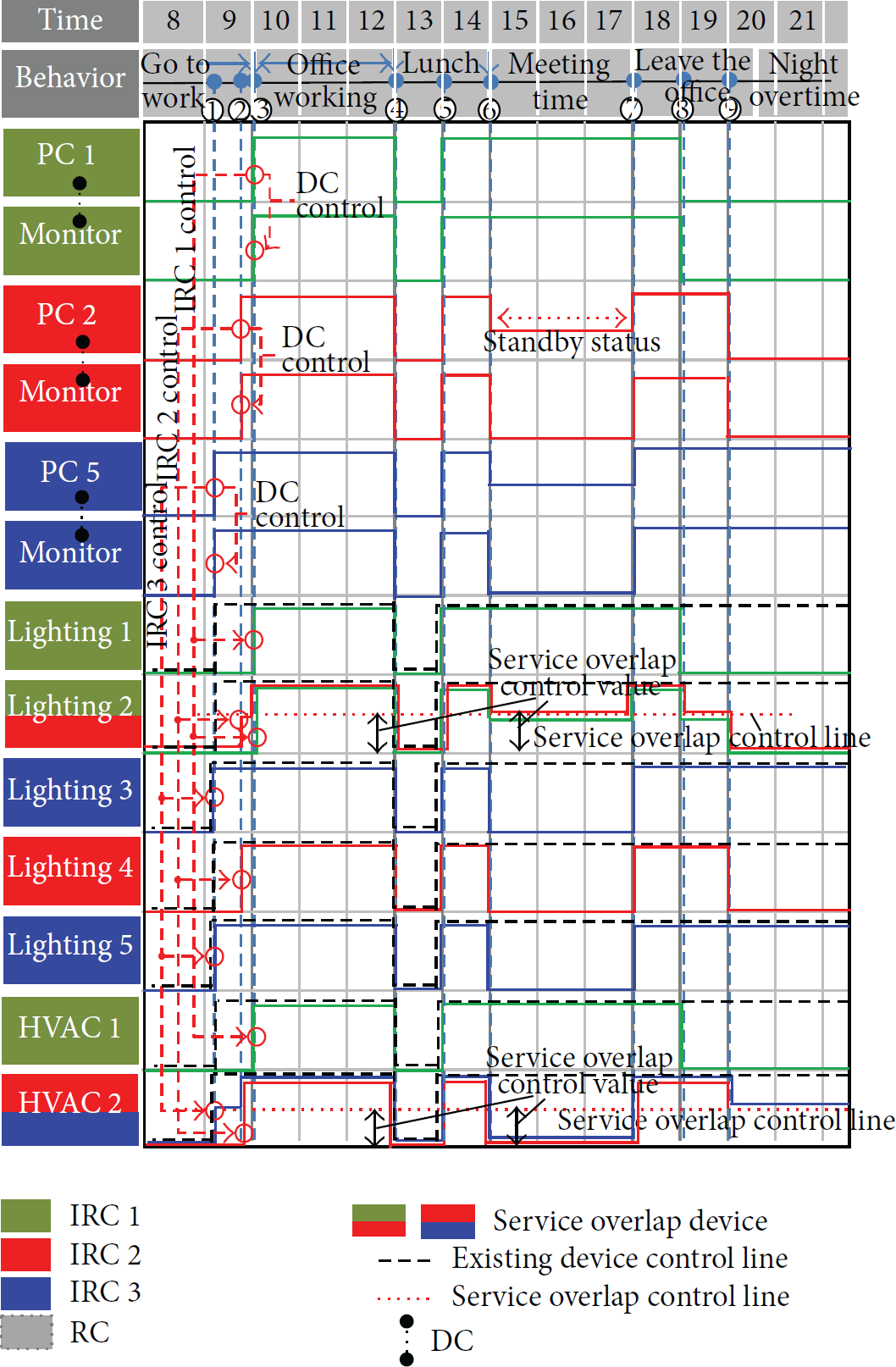
Three-chain control graph of each device in main office. ((1) The lighting illumination is 0% (lowest value), 50% (service overlap control value), and 100% (highest value). (2) HVAC intensity is low (lowest value), middle (service overlap control value), and strong (highest value). (3) The above graph shows all devices operating at constant values. (4) We suppose that the lighting and HVAC device are turned on when the first user enters the office (User 5 in Figure 8).)
5. Discussion
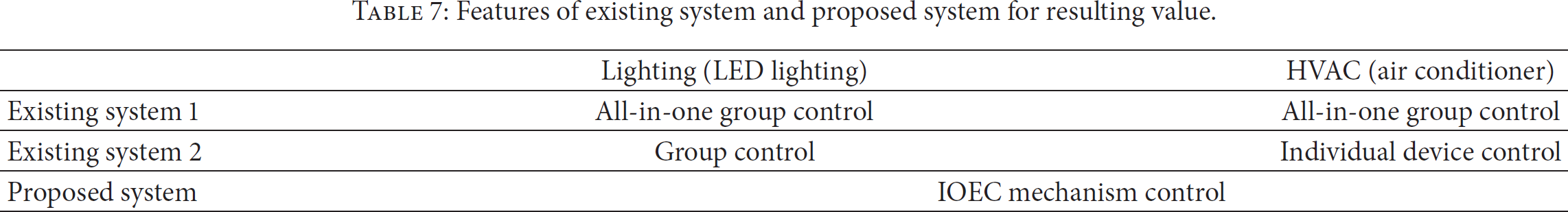
We calculated the energy efficiency rate based only on the power consumption of the lighting and HVAC devices in Tables 5, 6, and 7 and Figure 8. In Figure 8, the black dotted line is a control graph that shows the general device control. We considered two kinds of existing systems in Table 7, where we assumed that existing systems 1 and 2 turn the devices on at their maximum values from the time of “Go to Work” until “Leave the Office.” Figure 9 is a graph of the calculated energy consumption result by using the above conditions. Existing system 1 is a commonly used system, an all-in-one group controlled system when the device is on or off as shown in Figure 10 and Table 7. This system cannot be controlled by environmental information awareness; thus, it has a high energy leakage rate and low energy efficiency as shown in Figure 8. Existing system 2 operates by individual device control and group control. It can also reduce energy as shown in Figure 9, but there still exists an energy loss in the device control space; it is not possible below the limit for any energy savings, as shown in Figure 9. However, to improve energy efficiency and user satisfaction, the proposed system can control the situation-based autonomous energy optimization because it is connected between intelligent IoT devices (IOEC mechanism control) as shown in device control service scenarios #1 and #2. In addition, it can be controlled according to user behavior and can reduce the energy consumption by about 20.8% (existing system 1) and 15.0% (existing system 2) through the service overlap device control as shown in Figure 8. As a result, the focus of the proposed system is to show that it is possible to effectively control energy consumption in the office through the autonomous control of the IOEC mechanism between each device.
Features of existing system and proposed system for resulting value.

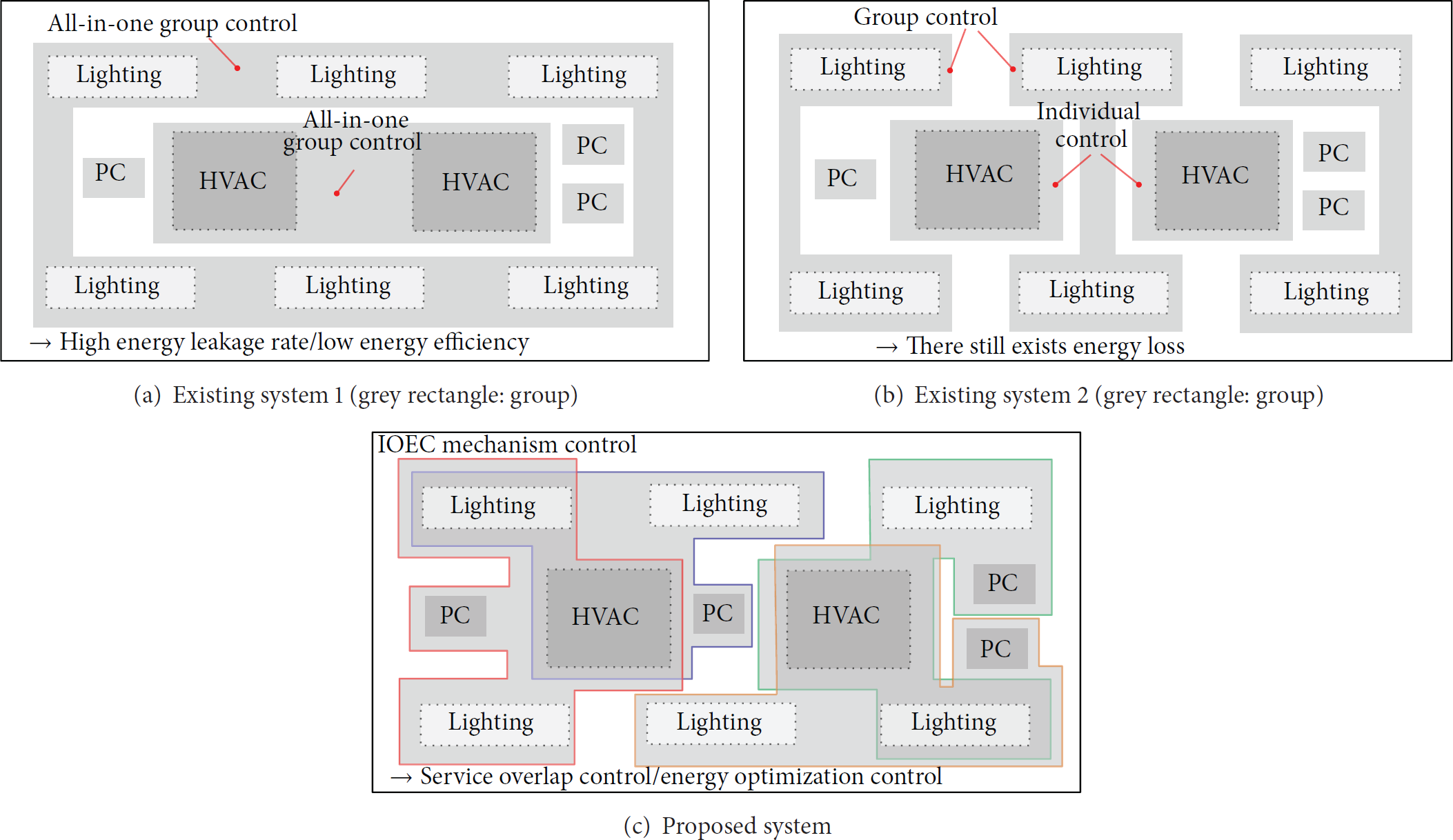
Features of existing system and proposed system.
6. Conclusion
Energy saving technology based on the IoT has become one of the most important trends. This paper shows the architecture of three-layer based energy-IoT BEACS as well as a mechanism for saving energy by automatically controlling the communication between each device through three different energy-IoT-based chains. Furthermore, this paper shows the scenarios-based control process of IRCs into three layers. The result of our study shows that the proposed system has a possibility of energy efficiency compared to the conventional two systems in Table 7. We believe that our proposed system can be used to control HVAC and power not only in buildings but also smart homes, smart town energy supply/management systems, vehicle information and communication systems, and so forth; it will provide more effective control methods for energy optimization hyperconnected object in IoT environment.
Footnotes
Conflict of Interests
The authors declare that there is no conflict of interests regarding the publication of this paper.
Acknowledgments
This research was supported by the MSIP (Ministry of Science, ICT and Future Planning), Korea, under the ITRC (Information Technology Research Center) support program (IITP-2015-H8501-15-1018) supervised by the IITP (Institute for Information & communications Technology Promotion), by the Human Resources Development program (no. 20154030200860) of the Korea Institute of Energy Technology Evaluation and Planning (KETEP) grant funded by the Korean government Ministry of Trade, Industry and Energy, and by the Chung-Ang University Excellent Student Scholarship.