
Abstract
This paper presents the performance analysis of wireless sensor networks- (WSNs-) based satellite collocation system as cooperative transmission is applied. A scenario of satellite cluster is considered, where multiple satellites are collocated with each other. Considering that the performance of satellite systems can be improved as the spot beam is split into virtual beams, the optimized system capacity can be expected by applying the geometrical arrangement of the antennas of transmitters and receivers. In the following simulation experiments, the system capacity is investigated as various system configurations are applied. It is found that the optimal value of system capacity exists as expected, and the simulation observations are illustrated as practical limitations are considered.
1. Introduction
Technological progress in wireless communications and microelectromechanical systems (MEMSs) have brought about the opportunity of the development of low-power, multifunctional, low-cost, and tiny sensor nodes which can communicate to each other directly. This progress, together with marked advances in the area of microsensors, has allowed inexpensive, energy-efficient, and reliable sensors with wireless networking capabilities to become a reality. The development of such devices has given rise to the increasingly popular concept of wireless sensor networks (WSNs) [1]. This network consists of a large number of nodes, which have sensing, processing, and communicating capabilities and perform human-unattended information collection [2], which has been the subject of extensive studies [3–5].
Nowadays, various kinds of WSNs-based application networks are attracting more and more attentions, such as smart grids [6], smart home [7], and e-health [8]. recently, wireless sensor network market also represents an interesting and potentially huge revenue stream for the satellite industry. The reason is that terrestrial network currently covers only 10% of the world and has created a need to switch toward satellite networks which would help to cover the remaining 90% of the world, making it the most attractive aspect of satellite sensor connectivity. In recent years, the research of combing wireless sensor network with satellite communication represents a good opportunity [9–11]. The wireless sensor satellite communication market comprises services such as environmental and habitat monitoring, satellite remote sensing for ocean research, and structural health monitoring. These services can make use of the backward satellite link capacity for the transmission of telemetry data, requiring only a small fraction of capacity in the forward direction.
In order to improve the capacity and spectral efficiency of satellite sensor network, the construction of multiple input multiple output (MIMO) systems is very promising especially with regard to satellite transmission. This is mainly due to two reasons: on the one hand, there is a rising demand for transmission bandwidth; on the other hand, the usable frequency spectrum of available bandwidth becomes short and particularly expensive. However, it is difficult for satellites to employ MIMO techniques directly on the existing satellite platform, due to the constraints from satellite's size or hardware implementation.
Compared to traditional MIMO systems, cooperative communication does not need multiple antennas at terminal devices and therefore significantly reduces the implemental complexity and cost, which is widely studied in wireless networks [12, 13]. The performance of cooperative transmission in satellite network is carried out in [14, 15], but only the low earth orbiting satellites scenario is considered. For the scenario of geostationary (GEO) orbiting satellite networks, only the limited numbers of satellites can be supported by the GEO orbit as GEO orbit is one kind of scarce nature resource. Unlike traditional GEO satellite system, multisatellite collocation technology [16], which can allow several satellites running in one GEO orbit window (
The main drawback of the satellite cooperative transmission system to be used in satellite sensor networks is found in satellite antenna element spacings, which are too small as several satellites are collocated with each other. In other words, these systems only offered low multiplexing gain coinciding with only a logarithmic rather than a linear increase of the capacity with the used number of antenna elements. In fact, there exist very distinct requirements for the positioning of both the satellite antennas and the ground stations that have to be fulfilled in order to create an orthogonal MIMO channel transfer matrix that offers optimum multiplexing gain. To overcome this problem, for terrestrial antennas system, the optimized antenna setups have been proven to deliver significantly higher channel capacities [18]. Contrarily, with respect to satellite systems, in [19–22], the maximum multiplexing gain of the line-of-sight (LOS) satellite channel is achieved by constructing an orthogonal channel matrix. However, for mathematically manageable results, the analyses are limited to a satellite cooperative transmission system with two satellite antenna elements only, which have to be placed on a single satellite each. In [23], a cooperative transmission scheme and a ground user selection criterion are proposed, but it also limited to the scenario with two satellites and two users. In the multisatellite collocation system, the use of multiple satellites can obviously improve multiplexing gain and spectral efficiency.
This paper addresses the optimization of the cooperative transmission channel capacity for a system consisting of
The remainder of this paper is organized as follows. The system model and channel model are given in Section 2. In Section 3, we describe a capacity calculation and optimum capacity. The optimization criterion is detailed in Section 4, and the performance analysis is given in Section 5. We conclude the paper in Section 6.
The superscripts H stand for the Hermitian transpose. Upper and lower boldfaced letters are used for matrices and column vectors, respectively. Denote by
2. System and Channel Model
2.1. System Model
A scenario of cooperative collocated satellite system is given in Figure 1, where at least two satellites collocated in one GEO orbit window and multiple users within one spot beam. Here, we suppose that there are
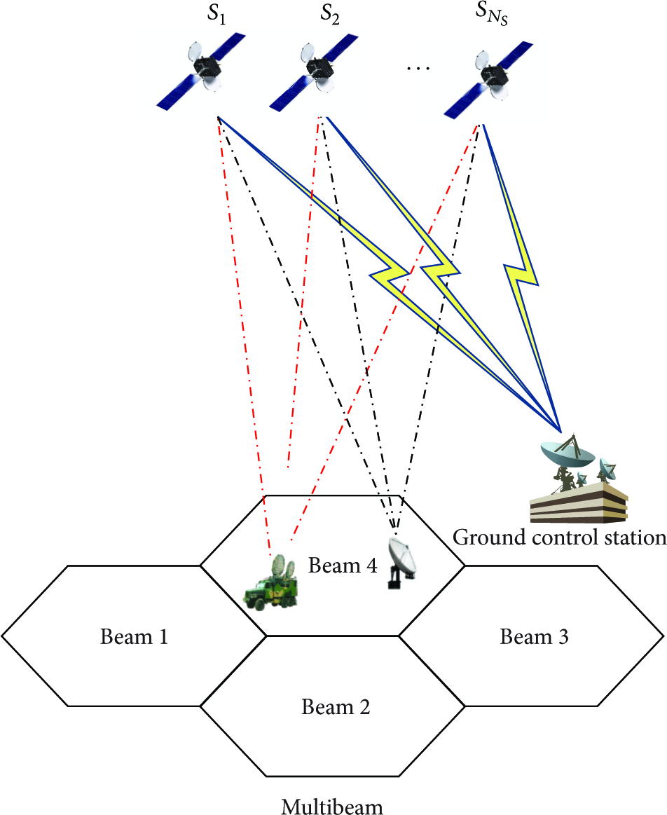
System scenario.
The system model is given in Figure 2. As is shown in Figure 2, selected terminals within one beam transmit data to multiple satellites simultaneously with the same frequency and time slot. After receiving the uplink data, satellites forward them to a ground control station. When a satellite terminal has a request for transmitting, the control station allocate a specific frequency and time slot to multiple selected users (for the sake of simplicity, only two satellite terminals are considered for cooperation).
System model.
The system characteristics and parameters are given in Table 1. Where EIRP is the effective isotropic radiated power,

Parameters of satellite system.

2.2. Channel Model
The frequency selective MIMO satelite channel 

Moreover, we assume the channel to be frequency flat if the bandwidth is much smaller than the carrier frequency; that is, 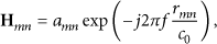
3. MIMO Capacity
3.1. Channel Capacity
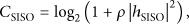
In the scenario of conventional satellite communication networks, with the help of Shannon theory, the capacity of a single-input-single-output (SISO) system is given by


3.2. Optimum Capacity
We define the square matrix 
Then, the maximum spectral efficiency is achieved when all eigenvalues of Q are identical; that is, 
This optimal capacity is also the upper bound we try to obtain in the following. Considering that the channel matrix is related with the distances between the satellite terminals and the satellites, so those path lengths are the degrees of freedom, which can be exploited to adjust the channel entries so that the eigenvalues of Q are equal, and thus
3.3. Cooperative Gain
In practice, if the LOS channel is not orthogonal for all satellites and satellite terminals, the capacity of cooperative system may not be better than that of noncooperative system. Therefore, following the definition given in [23], we define the cooperative gain generated by the cooperative transmission as follows:


4. Optimum Criterion
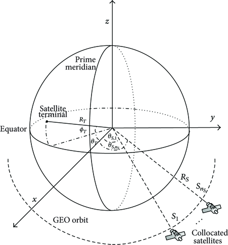
4.1. Geometrical Description
The principle of Mercator projection is used to obtain the positions of the satellites and satellite terminals. The geometrical description of satellite terminals is given in Figure 3, where the center of the satellite terminals has longitude 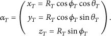
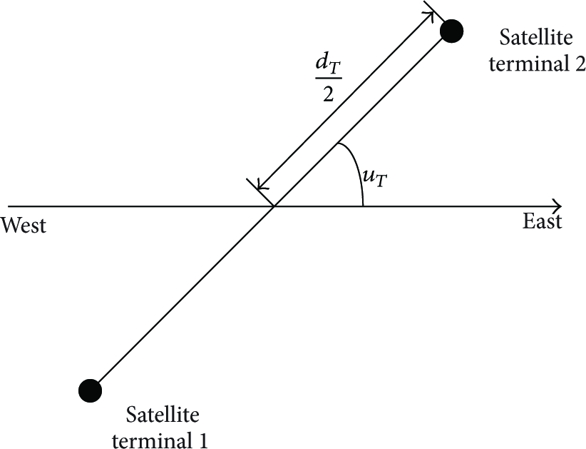
Geometrical description of two satellite terminals.
Then, we define the angle between a tangent in the east-west direction and the direction of two arbitrary satellite terminals is denoted by 
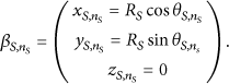
For each of the satellites, we may define
Thus, the distance between the nth terminal and the mth satellite is given as
Thanks to the approximation on the magnitude of the channel gain given by (4), it is actually shown that the phase relations between the channel matrix entries are the only degrees of freedom to modify the properties of the channel. As explained in Section 3.2, by imposing the eigenvalues of 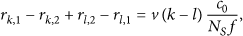
As a second step, we look for the expression of the length 
Inserting the position vector of 
Two auxiliary quantities are now introduced as

Now, we apply a first order Taylor series expansion as a good approximation of the square root 
This result may be inserted into (16), and we have

A comparison with this result for the equation obtained in [20] clearly shows that this time the optimization criterion keeps the dependence on the difference between k and l, while, in [20], this dependence disappeared; thanks to it, only consider two satellites, and the optimization of the positions of both satellites and terminals became independent of the choice of k and l. However, the term
Assume that the positions of satellites are given; in order to simplify (21), we first review the degree of freedom in the optimization of the position of two satellite terminals:
the number of transmit antenna the distance the direction angle
Assuming that 

Then, the optimization equation becomes

Now, we have one equation for each couple of
5. Simulation Results
In this section, we present performance results through numerical simulations, where two satellite terminals and multiple collocated satellites are considered.
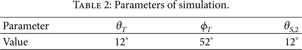
In Figure 4, we display the normalized achievable rate of cooperative and noncooperative system. Here, we assume that three satellites are chosen to communicate with two terminals. The simulation parameters are shown in Table 2, the distance between two satellites are set to 60 km, and the angle
Parameters of simulation.

Achievable rate for three satellites with cooperation, noncooperative satellites and one big satellite for
Figures 5 and 6 display the contour plot of the calculated system capacity as a function of
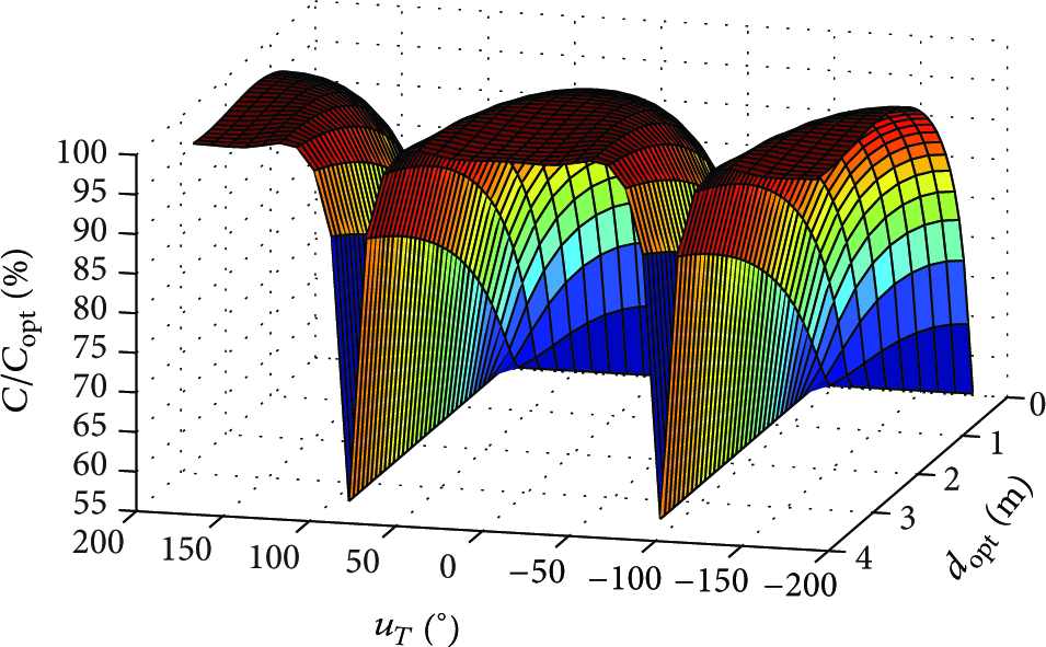
System capacity computed by numerical simulations for
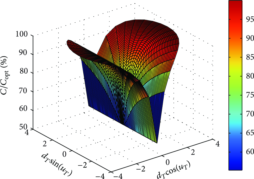
Polar coordinates representation of the system capacity computed by numerical simulations for
In Figure 7, we take into consideration to which degree any deviations from the optimum terminal distance setup will cause degradations of the system capacity. The figure shows that the system capacity C changes with the distance between two satellite terminals

System capacity with different
Figure 8 shows the value of optimal distance between two satellite terminals
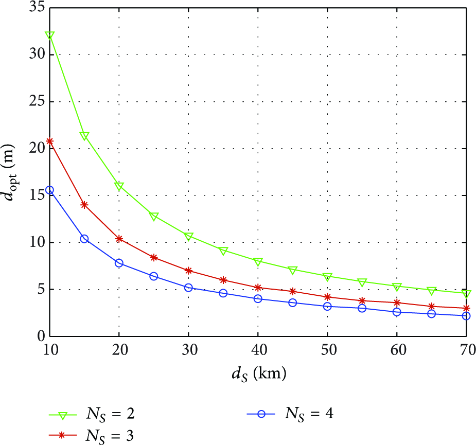
Optimal distance
Figure 9 shows the increase of the percentage of
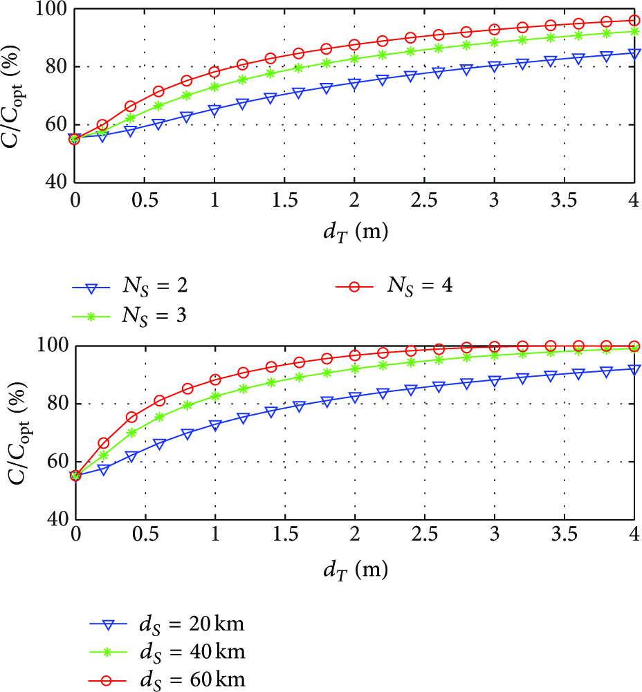
System capacity with different
In practice system, satellite is impossible to maintain absolutely immobile at its defined position. Therefore, a station keeping box is defined, which represents the maximum permitted values of the satellite excursions. For a capacity-optimized system, it is, thus, desirable to guarantee the optimum capacity as long as the satellite stays within this virtual box. Subsequently, we assume typical box dimensions, which are 37.5 km in longitude and latitude and 17.5 km for the eccentricity [26]. We have investigated the effect of satellite drifts in all three dimensions finding significant effects in cases of changes in longitude and latitude with respect to the nominal satellite position. Instead, the eccentricity remains of less relevance for the channel capacity. The capacity degradation is less than 1% of the optimum value
6. Conclusions
In this paper, we propose a scheme to combine satellite cooperative transmission networks and WSNs. The two sensor devices within one spot beam access a collocated satellite system for data transmission. With the help of cooperative beamforming, each satellite spot beam can be split into multiple virtual beams, by which the capacity can be improved. We present an approach which enables the construction of uplink with two terminals and multiple satellites that can achieve the maximum MIMO spectral efficiency for the case of LOS signal propagation. Maximum multiplexing gain is achieved via an optimized positioning and displacement of the MIMO antenna elements at both sides, which results in an orthogonal MIMO channel transfer matrix. Through simulations, we have confirmed that, for the construction of capacity-optimal MIMO channel transfer matrices, the user is provided with several degrees of freedom for the system design. It shows that capacity increases with the number of cooperative satellites
Footnotes
Conflict of Interests
The authors declare that there is no conflict of interests regarding the publication of this paper.
Acknowledgment
This work was supported by the National Natural Science Foundation of China under Grant no. 61231011.