
Abstract
This paper introduces infrastructure-to-vehicle (I2V) communication based on asynchronous optical camera communication (OCC), the transmitter of which can be an LED traffic light or electronic display, with the receiver being the existing front vehicle camera. In asynchronous OCC-based I2V communication, the key technique is an asynchronous scheme. An asynchronous scheme not only takes advantage of simplicity owing to the lack of an uplink or synchronization requirement, but is also the most feasible solution for communication to/from moving vehicles where synchronization is difficult to achieve within a short time. An asynchronous scheme for OCC-based I2V communication is proposed, and a performance evaluation shows its feasibility for use in a number of promising OCC-based wireless communication applications and services in a vehicular environment.
1. Introduction
In an intelligent traffic system, for safety reasons including cooperative driving and collision avoidance, along with the importance of in-traffic navigation, infrastructure-to-vehicle (I2V) communication is becoming more and more essential. Radio Frequency (RF) based communication in a traffic environment has shown tremendous growth and advantages but still maintains challenges such as signal interference and the difficulty in identifying where a signal is coming from in heavy traffic. Optical camera communication (OCC) might be another option for wireless communication in a vehicular environment.
An OCC-based I2V system can be deployed in an existing infrastructure such as LEDs traffic or electronic lighting signal sign acting as a transmitter and the front vehicle camera acting as a receiver. Compared to RF, OCC may be a better I2V solution because visible light and cameras are available, whereas RF has to be generated after a deep consideration of the unmitigated challenges. The advantages of OCC can be summarized as follows: (1) using existing infrastructure conditions without considerable modification (traffic lights or electric traffic signs as the transmitter and an in-vehicle camera as the receiver). In the near future, vehicles will be installed with full cameras as indispensable safety sensors [1]. (2) The achievement of OCC technology is increasing greatly and advances in both imaging and LED technology will eventually overcome the remaining limitations of RF technology. Moreover, OCC and RF are not competitive but work cooperatively to fulfill wireless vehicular communication.
According to the IEEE 802.15.7r1 revision of VLC, OCC study group [2–4], OCC commercialization has been approved and the group is moving on to the next step of standardization. OCC, when applied in a vehicular environment such as sending data regarding the traffic conditions and provision from infrastructure-to-car navigational guidance, is seen as a killer application that is shedding new light on intelligent transportation systems [1, 5]. Along with the contributions by the OCC study group, a large number of researches related to wireless communication in smart traffic systems based on OCC have been conducted in both past and recent years. Such researches have considered LED traffic lights as transmitters and high-speed cameras (1000 fps) as receivers. Some of these researches are worth highlighting [6–11] including a transmission protocol and image processing technique [6], encoding and decoding methods to improve the data rate from a long distance [7], an analysis of varying SNR ratio based on the distance and velocity [8], and an adapted encoding method for varying the distance necessary when the vehicle is moving [9]. Meanwhile, our previous work [12] provides the concept of a multicolor transmission on multiple LED channels, which could be helpful for further extension to heavy traffic conditions.
Asynchronous communication means that no synchronization is required for communication from the LED transmitter to the camera receiver. Figure 1 shows an example of asynchronous communication scenario between a vehicle and the traffic infrastructure. As shown in the figure, while moving closer to a traffic light, the car blinks its front LEDs to transmit a request to the traffic camera using an asynchronous communication scheme. An intelligent traffic system (ITS) server will also broadcast data from the traffic lights and LED traffic signs to the car using the asynchronous communication scheme. If synchronization is achieved, two modes of communication with an initially short processing time are required simultaneously, which is challenging to achieve under moving conditions.
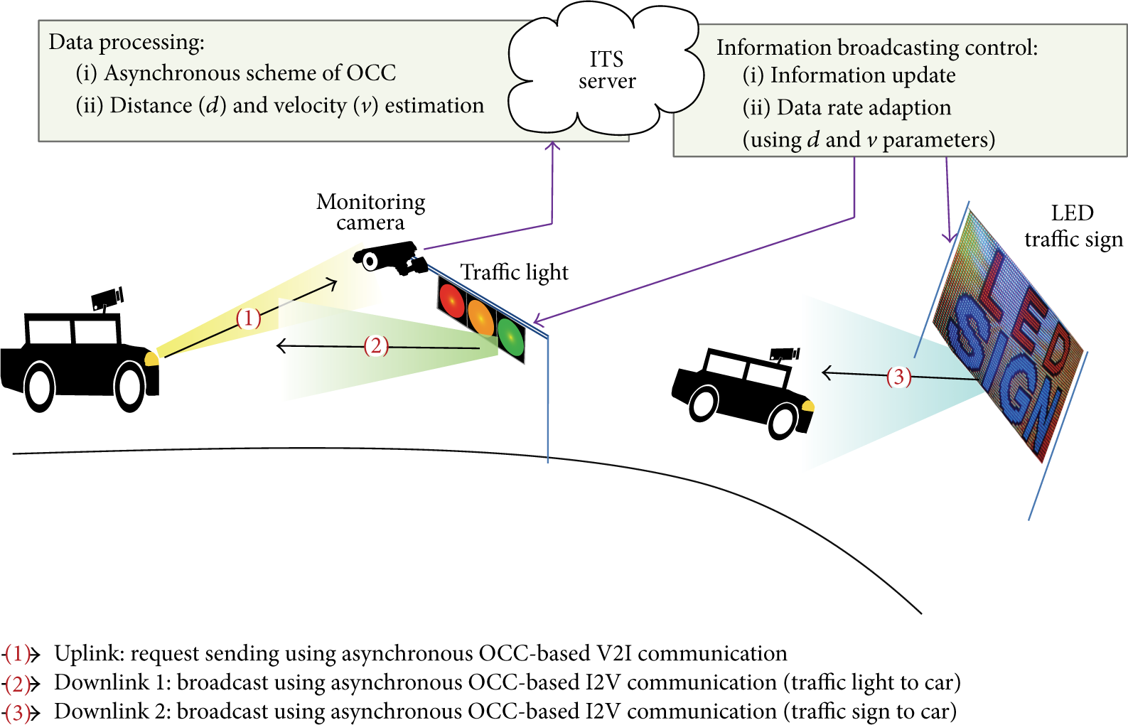
Scenario of asynchronous I2V communication using OCC. The front LEDs of the car send a request to a traffic camera. The ITS server will process the request from the car to control the traffic lights and LED traffic signs broadcasting the guidance information to the car.
This paper introduces asynchronous OCC-based I2V communication by proposing two asynchronous schemes for encoding and decoding. Asynchronous communication is important because of its simplicity without the requirement of an uplink, leading to a reduction in cost; in addition, it is suitable for a moving receiver such in a vehicle and can obtain data instantly from a traffic light or LED traffic display in which synchronization is either unavailable or overly challenging. Developed from our previous work on unidirectional OCC [13], the proposed asynchronous scheme is based on an oversampling technique and together with the proposed frame selection algorithm will allow camera to decode data without the requirement of synchronization. Novelty of this scheme is that we analyzed the effect of exposure time and variation of camera frame rate, usually ignored in other researches, in order to cancel or mitigate these problems. Comparing two asynchronous schemes, Scheme 1 allows receiver selecting the proper frames for decoding at fixed oversampling rate while Scheme 2 allows receiver selecting the proper frames for decoding at varied oversampling rate by using reference LEDs.
After introduction of asynchronous communication in vehicular environments given in this section, the remainder of this paper is organized as follows. Section 2 describes the architecture of an asynchronous I2V system and the challenges it might face, including the exposure time and variations in the camera frame rate. Section 3 proposes new asynchronous schemes along with an evaluation of their performance. Finally, experimental results and their discussion are provided in Section 4, with some concluding remarks given in the last section.
2. Unidirectional OCC and Its Challenges
2.1. Asynchronous OCC
Figure 2 illustrates the architecture of the unidirectional OCC system. LEDs are used to transmit data through visible light, and a camera is used as a receiver. The camera captures images continuously frame by frame, and every image frame is then processed and decoded into data. Because only one-way communication is used from the LEDs to the camera with no uplink required and therefore no synchronization, the unidirectional OCC is also called asynchronous OCC.

Architecture of asynchronous OCC using multiple LEDs.
An asynchronous transmission, set up without synchronization, can be applied to a brief transmission or the initial state of bidirectional communication. Synchronization is difficult to achieve during a short transmission time, especially in OCC, in which the frame rate of camera is varied and the time required for image processing is not fixed. Asynchronous OCC using an asynchronous decoding algorithm (see Figure 2) is indispensable for I2V communication.
2.2. Asynchronous OCC-Based I2V Architecture
Because the proposed architecture is used for a vehicular environment, a car, acting as transceiver with an uplink capability from its front LED to the traffic system and a downlink capability from the traffic light/sign to the front vehicle camera (see Figure 3), can move consistently at a considerably high speed. A high-speed camera is usually operating at 1,000 fps. At such short exposure time, it is able to capture images with acceptable blur while the car is moving. Due to high frame rate, the proposed asynchronous scheme for I2V communication using a Manchester coding scheme [2, 3] can certainly satisfy the requirement of mitigating any potential flickering.
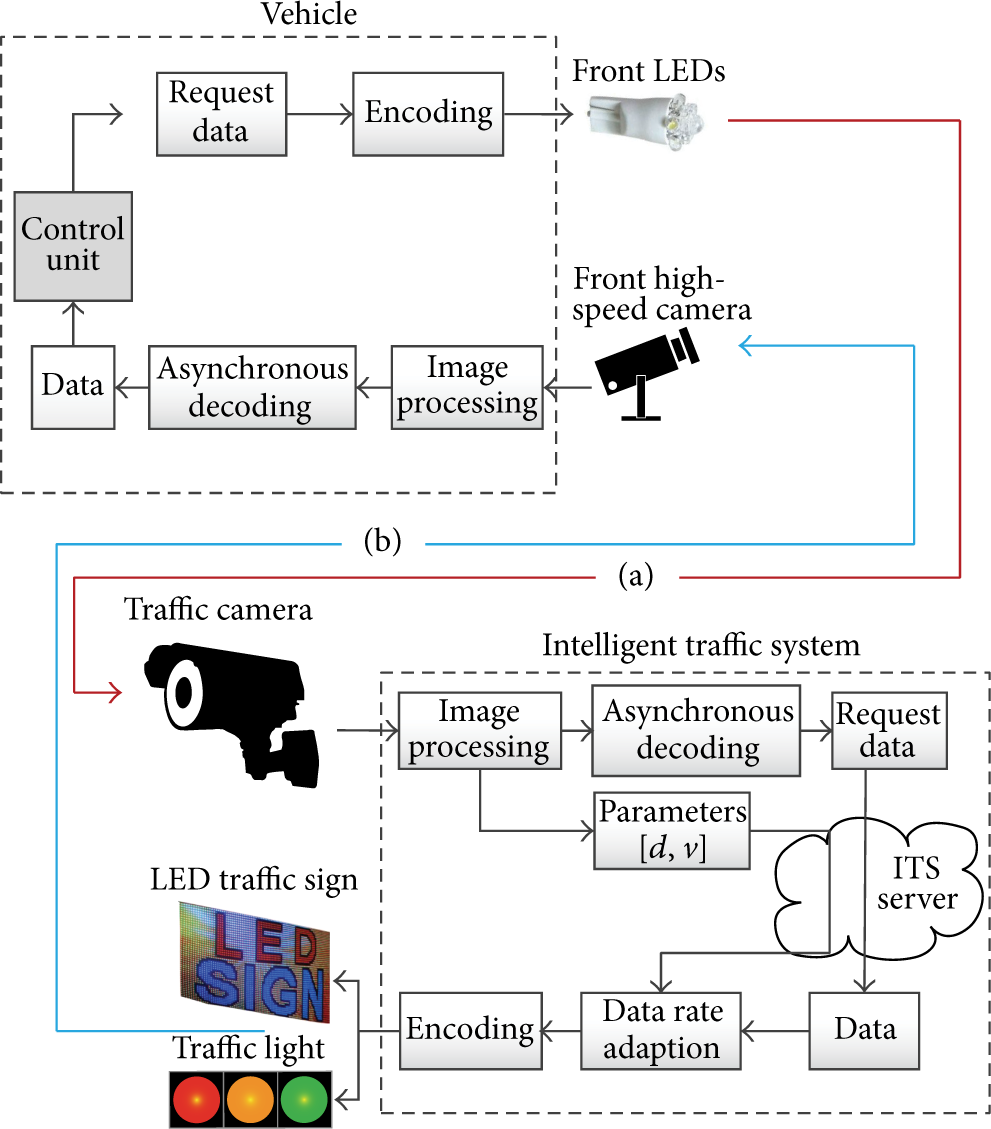
Architecture of asynchronous I2V communication using OCC: (a) uplink from vehicle-to-infrastructure (V2I) and (b) downlink from infrastructure-to-vehicle (I2V) communication.
Figure 3 describes the proposed architecture for bidirectional communication between a car and the infrastructure. The architecture uses the asynchronous transmission scheme previously detailed in the scenario shown in Figure 1. Initially, the vehicle's front LEDs blink a request to the traffic camera. The ITS server then updates the data according to the request from the vehicle and determines the vehicle's movement parameters, including its distance
2.3. Challenge of Exposure Time to Sampling
The exposure time (known as the shuttering time) of a camera is the time needed for capturing a single image frame. Normally, while transmitting data, the LED state turns on or off, and the value of the pixel output from the captured image should be close to 255 (maximum brightness) or 0 (minimum brightness), respectively. However, owing to the exposure effect shown in Figure 4, when a camera makes a random sampling, it leads to the appearance of poor frames in which the pixel value is in an unclear range, as shown in Figure 5, where the camera is making a sampling during the on-off switching time of the LED:


The moment of capture and the appearance of good/poor quality image frames.
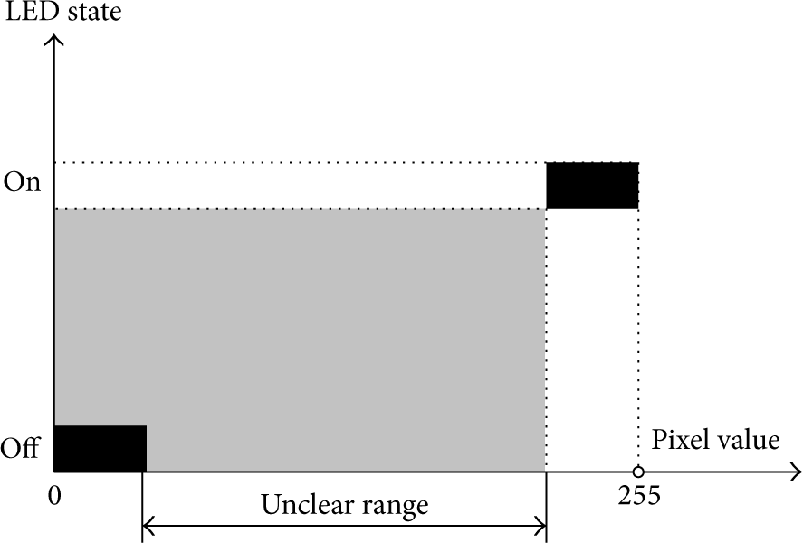
Relationship between pixel value and LED state.
In Figure 6, if the moment of capture is during a stable state of the LED (

Occurrence of poor image frames.
The appearance of a poor-quality image frame can be represented through a probability formula with a time relation, as in (2) and (3):


There is another effect of the exposure time related to the fast moving speed of the vehicle. While the image sensor is exposed, if the vehicle is moving too fast, it will cause a blurred image, which also results in an unclear range of the received pixel value, such as the poor sampling shown in Figure 4. In this case, an enhancement of the image quality is needed. If the state of the LED is still uncertain, the image is considered a poor sample and should be ignored, as shown in (3).
2.4. Challenge of Camera Frame Rate Variation
In most cases, it is believed that the frame rate of the camera remains constant, for example, at 1,000 fps. However, in our experiment, every camera has its own level of frame rate variation. The frame rate was measured, and the results show that the variation of the camera frame rate is irregular and unpredictable [13, 14]. The variation of the frame rate during a transmission cannot be predicted, leading to the fact that synchronization between the transmitter and camera (or receiver) is impossible. Each type of camera has its own level of variation depending on its technical parameters. This additional fact again confirms that an asynchronous scheme is indispensable to OCC-based I2V communication. A variation in the camera frame rate is illustrated in Figure 7 and is modeled through formula (4).

Variation in camera frame rate. DS indicates transmitting data subframe. An idle symbol is inserted between two adjacent DSs.
Between two subframes DSs, an idle symbol is inserted to avoid missing data with respect to the discrete sampling operation of the camera. The variation of the camera frame rate is formulated as

3. Proposed Asynchronous Scheme
Our goal is to propose an asynchronous scheme that allows data communication without the need for synchronization despite the frame rate of the camera changing during the data transmission. Owing to the effect of the exposure time and variations in the camera frame rate, an asynchronous scheme requires an image frame selection algorithm to choose the correct frames for decoding while ignoring other images. To achieve this, we propose two asynchronous schemes. The first scheme resolves the exposure effect of the asynchronous OCC system. This scheme is based on an oversampling technique and an image frame selection algorithm. Although the exposure time effect is negated, errors caused by variations in the frame rate will be evaluated. In contrast, the second asynchronous scheme is an enhancement resolving both the exposure effect and the frame rate variation. The idea in the second scheme is using reference signals to correct the frame selection algorithm and the asynchronous decoding step.
Assuming that the exposure value satisfies condition (4) as the initial condition of the exposure time in relation with the pulse rate,
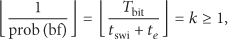
Condition (4) indicates that there is no more than one poor sample among k image frames captured. This is the initial condition used to make sure that a good quality image frame is selected and that not all of the frames are bad.
3.1. Scheme 1 with Stable Frame Rate
Consider a constant camera frame rate of 1,000 fps. Other ongoing commercial frame rates use the same method as the below oversampling rate. Because every camera has its own level of frame rate variation, the definition of a “stable frame rate” must be based on the accuracy requirement (the bit error rate (BER), as shown in (11)) of the system, which is described in the scheme performance evaluation below.
3.1.1. Methodology
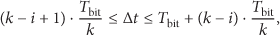
To solve the effect of the exposure value, “oversampling” is applied. The “frame selection algorithm” is then used to select the correct image frames for decoding the data, while other image frames need to be ignored. The oversampling condition is shown in

For condition (6), the number of transmitted data pulses is
The idea of this method is that when condition (6) is satisfied, the receiver side can select enough

Equation (7) satisfies condition (6). Now, the explanation of selection algorithm becomes that how to select two image frames among three adjacent frames. This is a specific case of the frame selection algorithm. Some different possibilities in this case may occur, as shown in Figures 8 and 9, resulting in different options when selecting two frames for decoding.
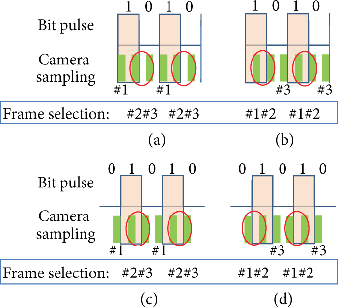
Two-frame selection (for no poor frames). Cases (a) and (c): selecting the last two of the three image frames. Cases (b) and (d): selecting the first two of the three image frames.

Selecting two good frames among three adjacent frames (when a poor frame appears).
Case 1 (no poor sampling among the three image frames).
In Case 1 (see Figure 8), because of condition (7), any of the circumstances shown in Figures 8 (a), 8(b), 8(c), or 8(d) could occur. Either the first two frames (cases (b) and (d)) or the last two frames (cases (a) and (c)) can be selected. If the first two image frames among the three frames are selected first, to avoid missing or repeating data, the selection of the two next images among the three frames must then also be the first couple. This case also applies to the last two frames. This means the first selection of the two frames among the three available frames will determine the following selection of the next two frames. For this case, we propose using a single LED acting as a reference that consistently blinks on and off evenly to help the camera make the proper selection.
Case 2 (poor sampling among the three image frames).
In Case 2 (Figure 9), there is only one poor frame among all windows of three adjacent frames and thus the selection is choosing the two good frames.
To summarize the selection algorithm, if no poor sampling occurs, the selection will be the first two (or last two) frames among the three frames. Otherwise, the bad sampling is the one needed to be ignored when decoding.
3.1.2. Performance Evaluation of the Proposed Scheme
As shown in the previous description of the selection algorithm, the effect of the exposure time leading to a poor sampling is cancelled by the selection. However, a variation in the camera frame rate while the data are transmitting will cause a BER. To evaluate the BER as a function of the variation in the frame rate of the camera, we consider the following:
Missing data then occurs when less than k frames are captured in the duration of

In addition, repeated data occurs when more than k frames are captured during

Without a proper selection of image frame, it causes the BER calculated by the sum of the missing image frames and the repeated image frames, which is then divided by the total number of image frames, k, as shown in

As can be seen in (10), the BER is dependent on the deviation in the frame rate (related to Δ) but is independent of the exposure time (related to the value of k).
In our special case, T = 1.5 ms, and

From (11), the BER, which represents the accuracy of the system, is proportional to the deviation in the frame rate of the camera. The more stable the frame rate of the camera, the fewer the number of errors that occur.
3.2. Scheme 2 with Unstable Frame Rate
In the previous scheme, a stable frame rate is required to avoid errors. The second scheme aims to allow a receiver to operate without error even if the frame rate of the camera continuously changes.
When the frame rate changes, to avoid missing data caused by the exposure time, oversampling is still needed, and condition (6) can be rewritten as follows:

After oversampling using condition (12) is satisfied, a new frame selection algorithm which is in order to avoid repeating data can be used to resolve the effect of the frame rate variation of the camera, as presented below.
3.2.1. Methodology
On the transmitter side, k LEDs are used, not for transmitting data but as a reference to help the receiver choose the correct image frames for decoding. These k LEDs have different phases (time delay). From the values of the pixels extracted from k LEDs per image frame, the transmitter knows the “capturing slot” (when an image frame is captured between the pulse lengths, as shown in Figure 10).

Identifying a slot for capturing a frame using four LEDs with a delay. Slots close to the bit transition will cause poor frames.
Because of variations in the frame rate of the camera, there may be more than one frame captured during a single pulse. To avoid repeated data, the capturing slot of the previous image frame along with the time counter,
Step 1 (determine the “capturing slot” using k LEDs for reference).
On the transmitter side, we use k LEDs, not for transmitting the data but for identifying the capturing slot of the image frame (the moment of frame capture within the pulse duration). These reference LEDs blink on and off evenly. With the first LED, the second LED delays
On the receiver side, decoded from a single image frame, there are always
Figure 10 shows an example for
For
Step 2 (image frame selection using a “capturing slot”).
See Figure 11.
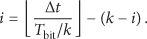
Assuming that the frame rate of the camera is never less than the pulse rate (to avoid missing data), there is one frame at least captured during a pulse length. To avoid repeated data, the following image frame selection algorithm is used. The value of

Choosing image frames using the capturing slot of the previous chosen image and the value of
An image frame that has a value of
If
3.2.2. Performance Evaluation
The accuracy of this asynchronous scheme depends on the value of k. The larger the value of k, the more accurate the capturing slot and thus the better the system performance.
In a real system, the transmitter will use the default pulse rate and the default number of LEDs, which means that k is also the default value. The receiver also has its own variation in the frame rate. Only one parameter can be modified, the exposure time of the camera, which needs to satisfy (4). However, it is known that the exposure has limited levels for the setup (corresponding to an integer of
4. Results and Discussion
4.1. Comparison of Asynchronous Schemes
Table 1 summarizes a comparison between the two proposed asynchronous schemes. Both schemes use an oversampling technique along with a selection algorithm to allow the receiver to choose the correct image frames for decoding. The oversampling rate is constant at two-thirds the total number of image frames in Scheme 1 but varies in Scheme 2, corresponding to the variations in the frame rate of the camera. Scheme 2 is more complex, not because of the amount of data, but rather owing to the larger number of LEDs required for transmitting the reference signals. Meanwhile, Scheme 1 is simple in its implementation but leads to some errors owing to the effect of the variation in frame rate of the camera.
Comparison between Schemes 1 and 2.
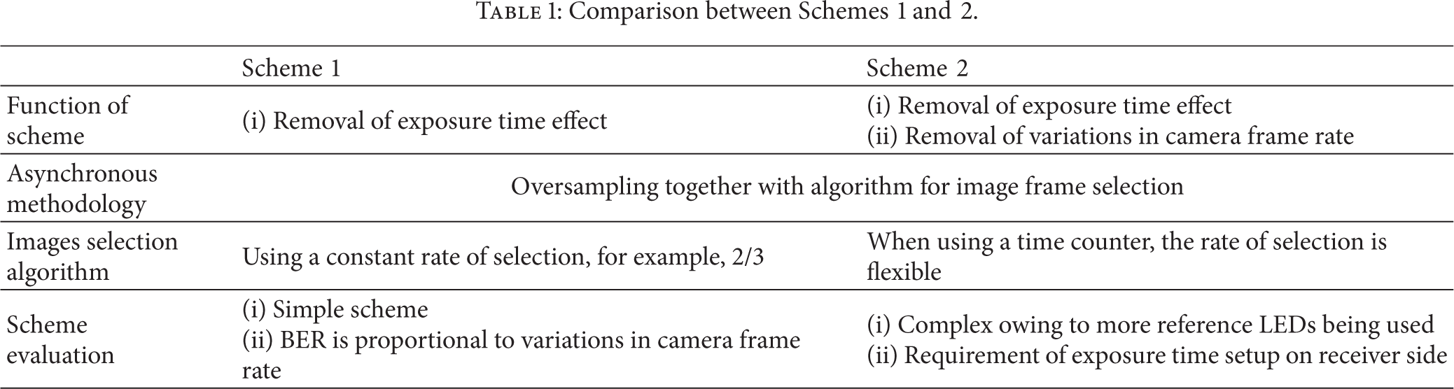
To mitigate the effect of the variation in camera frame rate in Scheme 1, forward error correction (FEC) is perhaps another solution instead of using more reference LEDs, as was applied in Scheme 2. Without using FEC, a BER as estimated in Figure 12 may occur. The BER rate calculated from (11) shows that the BER is proportional to the deviation in the frame rate of the camera.

The estimated BER varies based on the variation in the frame rate of the camera, which is around 1,000 fps, when Scheme 1 is applied. (1) shows the BER for the 2/3 frame selection algorithm with
4.2. Experimental Results
The first experiment is identifying the effect of the exposure time in the imaging operation. The LED transmitter blinks on and off, and the pixel values within the area of the LED in the captured image are then identified. Figure 13 shows that, when captured during the on-off switching time of the LED, the pixel value is uncertain and the state of LED cannot be identified.

Experimental relation between transmitted bits and pixel values in case of 20 pps transmitter and 30 fps camera used. It shows the uncertain states of LED occur when images are captured at switching time of LED.
Figure 13 shows the range of pixel values when the LED is in a constant on or off state. If the images are captured in switching time, they cause uncertain states of LED as analyzed in Section 2.
In order to model the variation of camera frame rate, the frame rate of different kinds of camera is monitored by measuring the interframe interval between image frames. Figures 14 through 15 show the estimated frame rate of different cameras. Experiment is conducted in various commercial cameras at 30 fps. The high-speed camera has faster speed of frame rate but it has same operation.
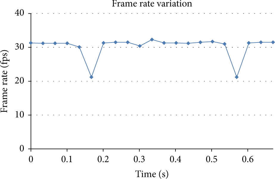
Experiment of variation in camera frame rate by measuring interframe interval (Samsung SPC-A400MB Camera). The frame rate of this camera type does not get influence by environment brightness at daytime or nighttime. This kind of camera is suitable for our schemes.

Experiment of variation in camera frame rate by measuring interframe interval (Colovis camera). The frame rate of this camera type drops considerably when the environment comes darker in order to balance brightness of image. This kind of camera is not suitable for our schemes.
As seen in Figures 14 through 15, cameras can be classified into two types based on the variation in frame rate. (1) Type 1 (Figure 14): camera frame rate is independent of environment brightness. Even in the dark environment or bright environment, the frame rate does not get any influence. This type of camera can be used for both daytime and nighttime. Most cameras we did test, including webcams and smartphone cameras, are of this type. This type of camera is suitable for our proposed schemes. The variation in frame rate is less than 30%. Therefore, Scheme 1 can be applied at fixed selection rate, 2/3. The repetition of transmission is required as the simplest error correction in this case. Scheme 2 can be applied in which the pulse rate is no larger than minimum frame rate of camera. (2) Type 2 (Figure 15): camera frame rate drops considerably when the environment becomes darker. It is because of the auto adjust to balance brightness of image. This type of camera has less frame rate at nighttime than at daytime. This type of camera is not suitable for our proposed scheme.
There is one solution to cancel the variation in camera frame rate that is firmware hacking [14]. By this way, frame rate is fixed and hence it is good for our schemes performance. However, the brightness of image seems to be unnatural. It may cause bad quality image due to lack of brightness balance.
We conducted an experiment to see which color is the best for transmitting the data, although the result depends on the use of a Bayer filter. Figures 16, 17, and 18 show the experimental results when white, red, and green lights are used to transmit data to the camera. In a traffic system, red and green traffic lights can be used to transmit data to a vehicle, whereas white can be used for an LED traffic sign.

Transmitted white light and received signals in red/green/blue channels.

Transmitted green light and received signals in red/green/blue channels.

Transmitted red light and received signals in red/green/blue channels.
The results of Figures 16, 17, and 18 show that the range in pixel value is not a problem for a single-color transmission (monochromatic light). However, the interference between the three channels, red, green, and blue, is also considerable. When using multiple colors to enhance the data rate of the transmission, interference between the color channels must be considered.
4.3. Promising Applications and Services of Asynchronous OCC-Based I2V Communication
Asynchronous OCC-based I2V communication can be applied anywhere a vehicle camera can be used as a receiver. In addition, lighting technology has entered the golden age of the LED, and any outdoor LED lighting device can act as an I2V transmitter.
Broadcasting service under vehicular conditions: one example of asynchronous I2V communication is the LED sign of a restaurant/shop acting as a transmitter, broadcasting information on a coupon promotion to the vehicles of interest. The LED sign blinks fast enough to be invisible to the human eye, and only those vehicles interested in such a coupon receive the information. Bidirectional I2V/I2V service: the proposed asynchronous schemes can be applied for a fast data transmission using OCC. The ITS service can receive any request from a registered vehicle (registration to the ITS service is required before use) and updates the broadcasting data for that particular vehicle. The capacity of the ITS system needs to be considered to allow the maximum number of vehicles to receive the data simultaneously. In our previous work [3], we described the concept of a multicolor transmission over multiple LED channels, which would be helpful under heavy traffic conditions. Relay car-to-car communication: car-to-car communication is a type of machine-to-machine communication in which the front car will broadcast and relay data to the rear car using its rear LEDs. This scenario will be helpful in the case of a traffic jam, where a vehicle very far behind may want to know what is happening ahead, for example, after a car accident has occurred. Moreover, if an ambulance is approaching, the ambulance may want the ITS to make way for an emergency situation. The ITS server can detect the situation using a traffic camera to update the broadcast data and then not only send guidance to the ambulance but also transmit an emergency message to some of the nearby cars. These cars that receive the emergency message from the ITS will have the responsibility to make way for the ambulance and relay the message to the vehicles behind them.
5. Conclusion
Asynchronous schemes were proposed to cancel the effect of the exposure time and mitigate the variation in the frame rate of a camera during a sampling operation. The algorithm and a performance evaluation of these schemes, as well as some scenarios and possible services, were introduced to reveal the feasibility of asynchronous OCC-based I2V communication in a vehicular environment. By comparison, Scheme 1 can remove the exposure effect but still generates errors when the frame rate of the camera continuously changes during a data transmission. Scheme 2 can mitigate the effect of this variation but is complex in terms of its implementation. Instead of Scheme 2, using Scheme 1 along with FEC may be a viable option.
As future work, enhancing the performance of the proposed schemes may be conducted as follows: (1) study a suitable FEC for asynchronous I2V communication based on OCC under various vehicle movement scenarios and (2) research multicolor transmission in multiple LED channels for the response data of a larger number of registered cars under heavy traffic situations.
Footnotes
Conflict of Interests
The authors declare that there is no conflict of interests regarding the publication of this paper.
Acknowledgments
This research was supported by a grant from the Fundamental R&D Program for Technology of Materials & Components funded by the Ministry of Trade, Industry and Energy, Republic of Korea. This research was also supported by the Basic Science Research Program through the National Research Foundation of Korea (NRF) funded by the Ministry of Education (no. 2013057922).