With the introduction of directional antennas into wireless networks, the beamwidth decreases and the range extends; thus both the mutual interference and the number of hops are reduced. This paper investigates the asymptotic throughput capacity and delay of hybrid wireless networks equipped with directional antennas. We first present a new scheme combining directional antennas and the same cell routing policy, and then derive the per-node throughput capacity and average delay in the proposed scheme, which mainly depend on the number of base stations m, the beamwidth of directional antennas θ, and the path loss exponent α. The discussions that how our directional hybrid wireless network explores the transmission range extension of directional antennas and how each parameter influences the throughput and delay are further elaborated. Moreover, our analytic results and experiments demonstrate that the substantial improvements on throughput capacity and the obvious reduction of average delay are achieved in hybrid wireless networks with directional antennas.
1. Introduction
With the growth of large-scale wireless applications in recent years, wireless networks capacity analysis has attracted great attention. Inspired by the pioneering work of Gupta and Kumar in [1], lots of succeeding researches give the insight into problem that how capacity scales with number of nodes. Particularly, the scaling laws in large-scale wireless networks and how to further enhance the throughput capacity become an interesting topic. There have been some excellent researches on capacity with some advanced techniques in different wireless networks, such as ad hoc networks [2–9] and sensor networks [10, 11].
The existing works are mainly under the assumption of equipping each node with an omnidirectional antenna. This may cause higher interference and affect performance of the network. Fortunately, the technology of directional antennas in [12, 13] can provide a promising solution for enhancing throughput in an efficient manner, with some useful features like the expanded coverage, the higher spatial reuse, and the reduced mutual interference [14, 15]. However, most of these researches considered only an ideal and simplified directional antenna pattern and ignored the effect of range extension for directional transmission. This property may benefit the performance in some realistic applications, such as laser communications. Up till now there are still no related works on the impact of range extension brought by directional antennas’ transmission in hybrid networks. It is also an emerging problem that how the range extension of directional antennas and other factors influence the performance of hybrid networks.
In this paper, we concentrate on the throughput capacity and average delay of directional hybrid networks with exploring the impact of range extension on network performance. We find that our approach can significantly improve the network throughput and delay due to reducing mutual interference and number of hops. The primary contributions of our research can be summarized as follows.
Different from existing researches, we propose a new scheme for asymptotic network performance analysis, which takes into account directional antennas’ range extension, wireless infrastructure (base stations), and practical routing policy. Moreover, our analytical results about the per-node throughput and average delay achieve the optimal order when the beamwidth of antennas is small enough.
We reveal that both the throughput capacity and average delay of hybrid networks differ with the number of base stations m, the beamwidth θ of directional antennas, and the path loss exponent α, respectively. In particular, when , no matter how to change the values of θ and α, the per-node throughput capacity scales as . The same result holds only when , . Furthermore, the average delay denoted by can be achieved when and in other cases only when . Therefore, substantial improvements on throughput and reduction of average delay can be obtained in terms of comparison tables and experiment figures, compared with the excellent works in [16, 17].
The remainder of the paper is organized as follows: In Section 2, we initially describe several related research efforts. Section 3 introduces our models and gives some definitions, which are fundamental for the analysis in our work. In Section 4, we derive the throughput capacity and delay scaling of hybrid wireless networks by taking the same cell routing policy and range extension of directional antennas into consideration. In Section 5, the performance comparisons with several existing literature are made and result discussions are given. We conclude this paper in Section 6 finally.
2. Related Works
Initiated in work [3], Liu et al. studied the throughput of hybrid wireless networks, which consist of an ad hoc network with n nodes and a sparse network of m base stations. When the total bandwidth of network is W and the k-nearest-cell routing policy is used, their results showed that the maximum per-node throughput is denoted by (The asymptotic notation means that, for two nonnegative functions and , denotes that is bounded as ; indicates as ; is equivalent to ; means and .) if the number of base stations m grows asymptotically faster than . Otherwise, the throughput scales as . Their research hinted that adding more base stations is obviously beneficial to throughput in certain circumstances, but it is rather pessimistic that the network does not scale well; that is, the throughput is tending to zero if the node number is large enough. Moreover, delay is not analysed, which is another important parameter in large wireless networks. A delay was defined in ad hoc networks and an optimal throughput-delay trade-off was proposed in fixed and mobile ad hoc networks [4]. Li et al. [18] first investigated using the L-maximum-hop resource allocation strategy in hybrid wireless networks and pointed out that throughput greatly depended on the number of maximum hops L and base stations m. Meanwhile, their conclusions indicated that hybrid wireless networks had greater throughput and smaller average packet delay than pure ad hoc networks in most cases. Furthermore, the per-node throughput capacity can be achieved when , which means the network is able to scale with more base stations. Particularly, Shila et al. [16] presented the bounds on capacity and derived the delay based on a practical same cell routing policy with multihop uplinks in hybrid networks. Their results showed distinct performance gains in comparison with some existing works, including pure ad hoc wireless networks [1] and hybrid networks [3].
In addition, Yi et al. [13] utilized an interference model to systematically analyse the capacity of ad hoc networks by using directional antennas, which include arbitrary networks and random networks, respectively. However, they focused on the lower bounds of capacity with directional antennas and showed obvious throughput gains in comparison with traditional omnidirectional antennas. Some other works, such as [17, 19, 20], studied the capacity of hybrid networks, wireless mesh networks, and sensor networks with directional antennas, respectively. In particular, Dai [20] showed that directional antennas in wireless sensor networks brought the improvement on the network capacity owing to reduction of the interference. Moreover, Zhang et al. [17] analysed the throughput capacity in hybrid wireless networks with each node equipped with a directional antenna. With the L-maximum-hop resource allocation strategy, they found that the per-node throughput capacity greatly depended on the maximum hop L, the number of base stations m, and the beamwidth of directional antennas θ on the basic of research in [18].
3. Models and Definitions
In this section, we will present our network model, directional antenna model with range extension, and our routing policy scheme as the basis. Some relative definitions are also introduced to facilitate our analysis.
3.1. Network Model
A hybrid wireless network which consists of n wireless nodes and a cellular infrastructure with m base stations is assumed in our analysis. Meanwhile, the whole network is considered to be uniformly and independently distributed on the surface of a unite area torus to avoid edge effects. We divide the unite area into m cells each of size and place a base station at the center of each cell in Figure 1. Furthermore, each cell is supposed to consist of subcells with equal-sized area . All n nodes are transmitting with the same power, thus having the same transmission range. These nodes are chosen randomly as source-destination pairs to forward packets according to the process in [2]. The base stations only serve as relays to help the wireless nodes to communicate with each other; hence they serve neither as source nodes nor as destination nodes. We also assume that the communications among base stations always have enough bandwidth, so it is not a bottleneck.
Network model and routing policy.
3.2. Directional Antenna Model with Range Extension
Compared with the existing research work, we put forward a directional antenna model with range extension to analyse the capacity and delay of hybrid wireless networks as in the description below and seek improvement on performance of our network model.
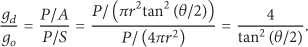
When transmission power keeps constant P all the time and transmission range of omnidirectional antennas is denoted by r, we borrow the antenna gain definitions and calculation methods from [20]. The gain value is defined as the directional antenna gain over the omnidirectional antenna gain . Suppose S and A represent the sphere surface area of omnidirectional antenna and spherical crown surface area of directional antenna in Figure 2, respectively. Furthermore, the latter surface area can be approximated to a circle with radius as for simplicity. With the help of simple geometric calculation, we derive
Surface areas of two antenna models. For sphere surface area of omnidirectional antenna, its radius is r. For sphere surface area of directional antenna, its radius can be treated as approximately.
Combining the general propagation model in [14], we get
where and are the transmitting power and receiving power, respectively, k is a constant influenced by antenna's property, and and are the gains of transmitter's antenna and receiver's antenna, respectively. The distance between transmitter and its receiver is assumed to be l, and the path loss exponent is denoted by α, which is often not less than 2. For simplicity, and are supposed to be the same when each node is equipped with the same antenna; that is, they are denoted as in circumstance with omnidirectional antennas, in contrast to with directional antennas.
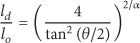
Assuming the maximum transmission distance with identical omnidirectional antennas in both transmitter and receiver is denoted as , while the maximum transmission distance with identical directional antennas is , we have
Substituting the ratio of and in (1) into (3), we easily obtain
which demonstrates that the transmission range with directional antennas is extended by . It follows our intuition that directional antennas can obtain larger transmission range by concentrating energy on a certain beamwidth; , and the larger transmission range brings higher throughput, improved connectivity, and increased spatial reuse. This property will play an important role in improving the throughput capacity and reducing delay for hybrid wireless networks in our model.
Assuming that a directional antenna with specific beamwidth θ is equipped for each node, the antenna of transmitter can arbitrarily cover a pointed direction. The directional transmission succeeds with probability of , and so does the directional receiving. Hence, the probability of forwarding packets successfully from a source node to its corresponding destination node is .
3.3. Receiver-Based Interference Model
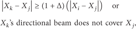
The interference model based on Protocol Model in [1] is used for analysing directional transmission and reception in hybrid wireless networks. Suppose that source node successfully transmits packet to its destination node only when no other nodes lie in the covered region of 's directional antenna beam and the beam of the two nodes , can cover each other. We define parameter as the size of an extra guard zone, and it follows conditions that
where node can successfully forward packet to node with directional antennas even when a simultaneous directional transmission from any other node occurs. This means the transmission from does not interfere with 's directional transmission.
3.4. Routing Policy Scheme
In the pure ad hoc mode, packets from source node to its destination node are forwarded in multiple hops without relying on base stations. However, in public cellular networks all nodes have to rely on respective base stations for transmitting packet even though they are located within a close range. This may increase both the burden of base stations and transmission time in large-scale wireless applications.
In hybrid wireless networks, transmitting nodes in different subcells can communicate not only with means of multiple hops but also with the help of base stations. The packets of source node are initially forwarded to the nearest base station by multihops and then sent to the base station that lies in the cell belonging to the destination node by wired transmitting and eventually to the destination node.
In this paper, we propose a directional same cell routing policy for hybrid wireless networks. Based on aforementioned depiction of network model, if source and destination nodes with directional antennas are in the same cell, and their directional antennas beams can cover each other, packets are successfully forwarded in the pure ad hoc mode, such as flows 1, 3, and 5 in Figure 1. Otherwise, packets are forwarded in the hybrid mode, such as flows 2 and 4 in Figure 1.
In addition, the total available bandwidth of common wireless channel is supposed to be W bits per second. It is further divided into three different frequency bands, for pure ad hoc transmissions, for uplink transmissions to base stations, and for downlink transmissions from base stations, respectively. Furthermore, the bandwidth for both uplink and downlink transmissions is the same; then we obtain . Consequently, .
Since three frequency bands are completely separate, we assume that three type transmissions are able to be carried out simultaneously and will not be interfered mutually. We can calculate per-node throughput for two modes separately, that is, pure ad hoc transmission throughput capacity and base station transmission throughput capacity , respectively. In the end, the sum of them is the per-node throughput capacity; that is, .
3.5. Definitions
Throughput. A per-node throughput denoted by bits per second is said to be feasible, if packet transmission rate from each source node to its chosen destination node can achieve bits per second, in a directional hybrid wireless network consisting of n nodes and m base stations. Meanwhile, the network throughput capacity is defined as since there are n S-D pairs (i.e., source-destination pairs) in the hybrid networks.
Average Delay. Similar to the definition in [21], the average delay in a hybrid network is the time that it takes for a packet with constant size from source node to its destination node, averaging over all the packets. In our analysis, we do not take queuing delay into account and denote as the average delay of every packet.
4. Throughput and Delay Analyses
In this section, we derive the throughput capacity and delay scaling of the proposed hybrid networks model under the same cell routing policy by considering range extension of directional antennas. Then we can obtain the following theorems.
Theorem 1.
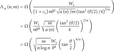
For a hybrid network with n nodes and m base stations, under the same cell routing policy by considering range extension of directional antennas, the throughput capacity furnished to every node is
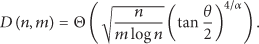
Theorem 2.
For a hybrid network with n nodes and m base stations, under the same cell routing policy by considering range extension of directional antennas, the average delay of every packet is
We will prove Theorems 1 and 2 separately. According to the depiction in our routing policy, the total throughput capacity of directional hybrid networks is comprised of pure ad hoc transmission throughput and base station transmission throughput . To begin with, the throughput capacity in our directional hybrid wireless network is derived as follows.
4.1. Throughput Capacity in Pure Ad Hoc Transmission
We will calculate in pure ad hoc mode, which includes a lower bound and an upper bound on the throughput capacity. Furthermore, the analysis procedure of the former is constructed based on the aforementioned network model and routing policy in Section 3.
Lemma 3.
If goes greater than , each subcell has at least one node with high probability.
This lemma can be proved similarly according to well-known probability conclusions in [22]. It is important that this condition can guarantee the existence of S-D pairs whose transmission through any subcell in a cell succeeds with high probability. In addition, similar to [1], we define two subcells as interfering neighbors when there are any nodes in one subcell that are within a distance of some nodes in other subcells. It is easily followed that when the two subcells are not interfering neighbors, the transmission across one subcell cannot be interfered by the simultaneous transmission passing through another subcell.
Lemma 4.
When the directional antennas with range extension are used by the nodes in our network, each subcell has no more than interfering neighbors, where is a variable that is dependent on Δ, θ, and α and, however, independent of n, m, and .
Proof.
Since the area of each subcell is , the transmission range of omnidirectional antennas is chosen as so that any node in a subcell can transmit successfully to some other node lying in its neighboring subcells; also directional antennas can extend their transmission range up to times; that is, . It is easily followed that each subcell can be totally covered by a disk with radius . In a particular subcell, we assume that there are two nodes far away from each other belonging to it and their distance is no more than . According to the definition of interfering neighbors, there should be other nodes in the particular subcell's interfering subcells that lie at a distance of with the above two nodes, respectively. The interfering area of the particular subcell should cover itself, its interfering subcells area, and the distance area between them. Hence, the interfering area is derived as edge length no more than , bounded by . In addition, with beamwidth θ, the directional antenna beam of transmitter and its receiver should point at each other to ensure successful transmission. Also each node in a subcell can be interfered when it is covered by directional antenna beam of any other node. Thus, the average probability that nodes interfere with each other is . Combining the above results, we infer that the number of interfering subcells is at most = .
Lemma 5.
For a given cell k with size as , the numbers of S-D pairs communicating using pure ad hoc mode and the hybrid mode are and under the same cell routing policy, respectively.
See [16] for proof in detail. This lemma is meaningful to bound the number of S-D pairs communicating using pure ad hoc mode and the hybrid mode in a given cell, but for simplicity it does not take into account the effects of practical directional antennas with range extension on packets’ successful transmission. In contrast, we will extend the analysis and exploit this property to exert an influence on some parameters of network performance, such as throughput and average delay.
Lemma 6.
The number of S-D pairs passing through any subcell in a cell and forwarding packets successfully is with high probability.
Proof.
For an arbitrary cell k, there are S-D pairs communicating using pure ad hoc mode in cell k on account of Lemma 5. We suppose that is the distance of the S-D pair i and is the number of hops for S-D pair i to transmit every packet on average. Since each hop covers a distance of , we have . Define the Bernoulli random variables for S-D pairs and hops as follows:
Thus, the total number of S-D pairs passing through a subcell according to the pure ad hoc mode is . The total numbers of hops for a packet over all S-D pairs in pure ad hoc mode are . For directional antenna with specific beamwidth θ, the event that any node in the subcell can be chosen as the receiver of corresponding source node and transmit successfully occurs with probability . Meanwhile, is no more than the side length of each cell. Under the same cell routing policy using directional antenna, we have , and
In the above analysis, it should be noted that there are subcells in the given cell and the probability of any hop deriving from any subcell is identical. Moreover, we need to bound the total number of S-D pairs passing through a subcell according to the hybrid mode. Thus, based on the similar techniques, we have . On account of independence between and , we can obtain the total number of S-D pairs passing through any subcell in a given cell and forwarding packets successfully as summation of and ; that is, . Also using the similar method in [4] and setting the arbitrary positive parameter , we bound the number of S-D pairs passing through any subcell in a cell and forwarding packets successfully by with high probability not less than .
We use a time division multiaccess (TDMA) scheme to schedule the packets transmission. It follows from Lemma 4 that the number of adjacent subcells which interfere with a subcell is at most; this demonstrates that every subcell will be active once in every time slot. As Lemma 6 points out, to guarantee successful transmission every S-D pair can use one subslot if each subcell divides its time slot into subslots. In other words, every S-D pair has opportunity to transmit successfully through one subslot; that is, every S-D pair can hold the fraction of time for passing through any subcell in a cell and forwarding packets successfully as . Since frequency band bits per second is available for pure ad hoc mode, an achievable lower bound on throughput capacity is
as .
Next, we will arrive at an upper bound on the per-node throughput capacity for pure ad hoc mode under the same cell routing policy by considering range extension of directional antennas.
Lemma 7.
Based on equipping directional antenna with range extension for each node, the number of simultaneous transmissions possible over any particular channel is no more than
in the Protocol Model.
Proof.
We consider the Protocol Model in [1] by equipping directional antenna with range extension for each node; if node is transmitting packet successfully to its destination node on a channel, there is another simultaneous transmission from node to node on the same channel. From the triangle inequality and our receiver-based interference model, we have
Similarly,
We sum the above two inequalities and find
According to the Protocol Model that and , we obtain
Therefore, disks with radius centered at and on the same channel at the same time are essentially disjoint. Meanwhile, we can use directional antenna to decrease every such disk area, since its beamwidth θ is fraction of omnidirectional antennas. Then each such disk area is , when we consider directional transmission and directional receiving. Hence, our network can support no more than simultaneous transmissions on the particular channel.
Since a common wireless channel is assumed to be shared by all nodes and frequency band bits per second for each transmission is available for pure ad hoc mode, the total number of bits transmitted simultaneously is no more than on the channel. We also suppose is the average distance for transmitting a packet in pure ad hoc mode and derive that average number of hops that a packet needs to go through in a given cell is at least. Therefore, each bit is averagely required to be retransmitted by at least relay nodes. Meanwhile, every source node sends out bits per second; there are source nodes. Each of them is equipped with a directional antenna and we have a probability of to transmit successfully to its destination node. Then it follows that the given cell can generate at least bits per second. Note that there are above m cells in our whole network; we easily derive that the network can serve totally bits per second at least. To ensure that all the required transmissions in pure ad hoc mode are forwarded successfully, we should claim
that is,
In addition, is no more than the length of each cell and meets based on Lemma 3; we conclude
Consequently, the upper bound on the per-node throughput capacity for pure ad hoc mode is derived by . Together with (10), we completely obtain the throughput capacity in pure ad hoc node furnished to every node as .
4.2. Throughput Capacity in Base Station Transmission
On account of frequency reuse policy adopted for avoiding interference from adjacent cells, when there are adjacent cells which can interfere with each other, the bandwidth will be shared and the range of the bandwidth occupied by every cell is ; that is, the throughput capacity per cell in base station transmission is .
Since the area of every cell is , there are nodes in every cell. Thus, throughput capacity of every node in a cell is . Combining the aforementioned analysis in the ad hoc mode, we obtain the throughput capacity furnished to every node in our directional hybrid wireless network. Then the proof for Theorem 1 is completed finally by this time.
4.3. Average Delay of Directional Hybrid Wireless Networks
Now we will calculate the average packet delay . According to previous studies in [4, 16], we assume that the transmission delay at every node is a constant; per packet delay is proportional to the average number of hops required to reach its destination in a S-D pair. Meanwhile, each hop covers a distance of ; the number of hops for each S-D pair i to transmit every packet on average is . The average numbers of hops required by a packet over all S-D pairs are , because the length of each S-D pair is at most in pure ad hoc or the hybrid mode. On the other hand, we assume that is the average distance for transmitting a packet in pure ad hoc mode and obtain the average number of hops required by a packet in a cell as at least. Consequently, combining the fact and aforementioned relations of relevant parameters, we obtain the average number of hops to be . The average packet delay is proportional to the above value.
5. Results Discussion and Performance Comparison
In this section, we firstly discuss how each parameter makes a different influence on throughput and average delay.
If , then we could have higher throughput capacity when and . Hence, we get
In this case, increasing the number of base stations can linearly increase the per-node throughput when the number of base stations is below the upper bound n. Network capacity attains the maximum order if we keep adding base stations up to n. At this moment, directional antennas have no significant impact on throughput capacity because base stations entirely dominate the network transmission in the hybrid mode.
If , then we could obtain higher throughput capacity when ; that is, . Consequently, . According to the depiction of directional antenna model with range extension, the path loss factor α is often no less than 2, and the beamwidth θ of antenna is quite small. Therefore, . When the path loss factor α is set to be 2 for simplicity, we approximately derive .
If , we obtain the highest throughput capacity as . This means the throughput capacity furnished to every node can be large enough and up to , when the beamwidth of antenna is small enough. At this moment, the wireless network can scale well.
If , the fact arrives, as . Since beamwidth θ of antenna is bounded, the throughput capacity of every node is mainly determined by m and n. The wireless network cannot scale well at this moment.
In the case of limited number of base stations, when we add some base stations or diminish the beamwidth of antennas, the per-node throughput can be increased significantly. Moreover, it shows that if the number of base stations is fixed, the per-node throughput can approximatively increase up to the maximum order with the reduction of antennas’ beamwidth. Otherwise, when we add the beamwidth of antennas to some extent; the per-node throughput will decrease to zero with increasing number of nodes. Therefore, the directional antenna and its range extension have significant impact on throughput, when the pure ad hoc mode dominates the network transmission.
If , we could have average delay . This hints that adding the number of base stations can effectively reduce the average delay and the directional antennas do not affect the average delay obviously in this case.
If , average packet delay is obtained. According to the aforementioned similar technique of directional antenna model with range extension, the path loss factor α is set to be 2; we have . In this case, the beamwidth of directional antennas will influence the average delay essentially. It reveals that we can reduce the average delay by means of controlling the beamwidth of directional antennas.
If , is derived. We observe that the average delay increases with the beamwidth of directional antennas at this time.
If , it is easily followed that . It seems to be possible to have a constant average delay when the beamwidth is adjusted to be small enough. This case is suitable for improving timeliness of large-scale wireless, especially when users cannot tolerate transmission delay.
In addition, we present capacity gain defined as = capacity of our scheme/capacity of other existing schemes and delay gain as = delay of other existing schemes/delay of our scheme, respectively. Meanwhile, we will make a comparative performance analysis between our proposed scheme and some other existing schemes.
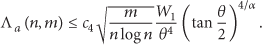
(1) Comparison with Hybrid Networks Equipping Omnidirectional Antennas. It is shown in [16] that authors considered the same cell routing policy for hybrid networks. Their contribution follows two regimes, respectively; when , throughput is achieved and average delay is bounded by . Moreover, when , throughput capacity and average delay are achieved. Comparing them with our results in Table 1, we obtain capacity gain from several aspects in Table 2. In particular, when , capacity gain is and delay gain is . Figure 3 compares the per-node throughput capacity achieved in our directional antennas scheme with omnidirectional antennas schemes in [1, 16] as the number of base stations increases. In Figure 4, we illustrate our gain of average delay in all aspects compared with conventional works in [2, 16]. Furthermore, when the beamwidth θ is set to be and the path loss factor α as 2, our scheme achieves capacity gain about 1.7 and delay gain beyond 1 by a simulation in Figure 5. This demonstrates that further exploiting directional antennas with range extension can significantly achieve obvious improvements on throughput capacity and average delay under the same cell routing policy.
Throughput capacity of hybrid network with our scheme.
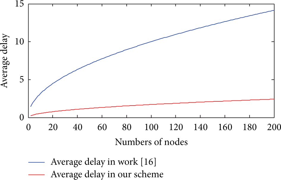
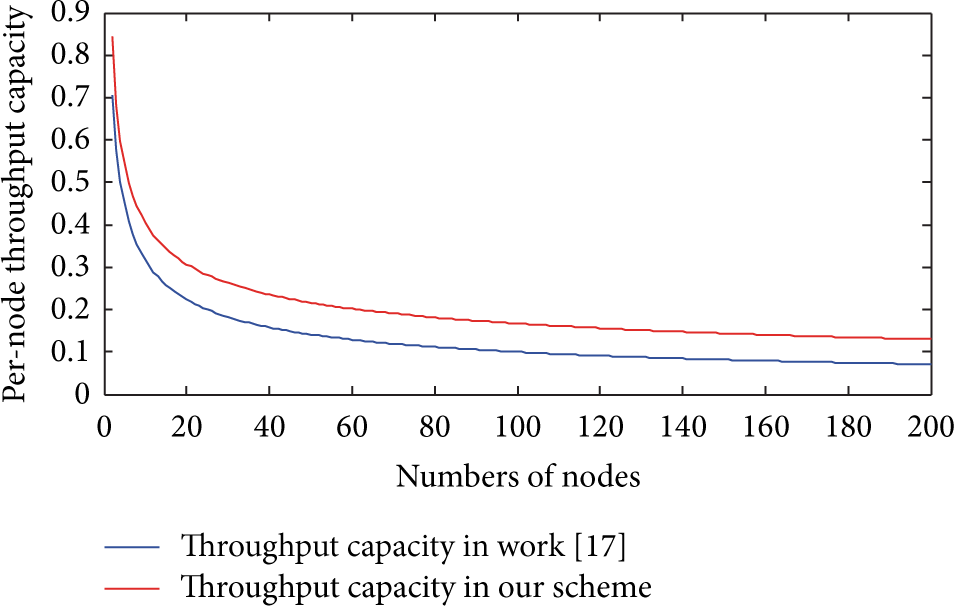
Per-node throughput for our directional antennas scheme and omnidirectional antennas schemes in [1, 16].
Average delay for our directional antennas scheme and omnidirectional antennas schemes in [2, 16].
Average delay when , , , in comparison with work [16].
(2) Comparison with Hybrid Networks Equipping Directional Antennas. In work [17], authors analysed the throughput capacity of hybrid directional wireless networks under the L-maximum-hop resource allocation strategy. Their results are shown as follows: (a) when and , the throughput capacity scales as . Otherwise, when , the per-node throughput capacity is bounded by . (b) When and m grows faster than , they obtain throughput capacity . Otherwise, when m grows slower than , the per-node throughput is achieved. Compared to our scheme with directional antennas, the obvious difference is that they do not consider the range extension of directional antennas, besides the modified routing policy. In Table 3, we show capacity gain from several aspects. For example, when we set L to be and m as , our scheme can reach a gain of over the scheme of [17]. Specially, when we consider a wireless network with 200 nodes, capacity gain about 1.8 is obtained and we derive a visible improvement on throughput with the increasing number of nodes in Figure 6. The reason behind our gain is that we use not only the same cell routing policy but also the directional antenna with larger transmission range, which could attain higher throughput to a great extent.
Per-node throughput when , , , in comparison with work [17].
6. Conclusion
In this paper, we explore the narrow beamwidth and extended transmission range introduced by directional antennas and study their improvements on capacity and delay in directional hybrid networks. Under the same cell routing policy, we derive the per-node throughput capacity and average delay in hybrid networks which are related to the number of base stations m, the beamwidth of directional antennas θ, and the path loss exponent α. Then we analyse the significant impact on network performance and average delay in all kinds of cases with directional antennas and their range extension. Specially, the per-node throughput and average delay can achieve the optimal order when the beamwidth of antenna is small enough. This benefit mainly comes from directional antennas which can support extension of transmission range, reduce mutual interference, and decrease the number of hops. However, applying this potential into reality may require synergistic support for antennas adjustment at several protocol layers, and it probably results in greater energy consumption. Therefore, how to develop more effective transmission schemes for directional wireless networks with cross layer protocol and analyse performance under energy constraint may be our future research work.
Footnotes
Conflict of Interests
The authors declare that there is no conflict of interests regarding the publication of this paper.
Acknowledgments
The authors would like to thank the editors and the anonymous reviewers. This work was supported in part by the National Natural Science Foundation of China nos. 61390513 and 61173041, Huawei Innovation Research Plan (HIRP) Funding no. YB2014030033, National Science and Technology Major Project of China under Grant no. 2014ZX03003003, Equipment Manufacturing Systems and Optimization no.13XKJC01, and National Science and Technology Support Plan Grant no. 2012BAH15F03.
References
1.
GuptaP.KumarP. R.The capacity of wireless networksIEEE Transactions on Information Theory200046238840410.1109/18.8257992-s2.0-33747142749
2.
GrossglauserM.TseD.Mobility increases the capacity of ad hoc wireless networksProceedings of the 20th Annual Joint Conference of the IEEE Computer and Communications Societies (INFOCOM ’01)April 2001Anchorage, Alaska, USA13601369
3.
LiuB.LiuZ.TowsleyD.On the capacity of hybrid wireless networksProceedings of the 22nd Annual Joint Conference on the IEEE Computer and Communications SocietiesApril 2003San Francisco, Calif, USA154315522-s2.0-0042014447
4.
El GamalA.MammenJ.PrabhakarB.ShahD.Throughput-delay trade-off in wireless networks1Proceedings of the 23rd Annual Joint Conference of the IEEE Computer and Communications Societies (INFOCOM '04)March 20044644752-s2.0-414311246010.1109/INFCOM.2004.1354518
5.
ToumpisS.GoldsmithA. J.Large wireless networks under fading, mobility, and delay constraintsProceedings of the IEEE Conference on Computer Communications (INFOCOM '04)2004Hong Kong609619
6.
LinX.ShroffN. B.Towards achieving the maximum capacity in large mobile wireless networks under delay constraintsJournal of Communications and Networks20046435236110.1109/JCN.2004.65968362-s2.0-11144275997
7.
NeelyM. J.ModianoE.Capacity and delay trade-offs for ad hoc mobile networksIEEE Transactions on Information Theory20055161917193710.1109/tit.2005.8477172-s2.0-20544449224
8.
PeiY.AmbetkarV. S.ModestinoJ. W.WangX.On the throughput capacity of hybrid wireless networks using an L-maximum-hop routing strategyWireless Personal Communications2007421414810.1007/s11277-006-9165-z2-s2.0-34250173814
9.
WangC.JiangC.LiX.-Y.LiuY.Multicast throughput for large scale cognitive networksWireless Networks20101671945196010.1007/s11276-010-0237-32-s2.0-77957892637
10.
LianJ.NaikK.AgnewG. B.Data capacity improvement of wireless sensor networks using non-uniform sensor distributionInternational Journal of Distributed Sensor Networks20062212114510.1080/155013205002012762-s2.0-34548851055
11.
ZhengH.XiaoS.WangX.TianX.GuizaniM.Capacity and delay analysis for data gathering with compressive sensing in wireless sensor networksIEEE Transactions on Wireless Communications201312291792710.1109/TWC.2012.122212.1210322-s2.0-84874947147
12.
YiS.PeiY.KalyanaramanS.On the capacity improvement of ad hoc wireless networks using directional antennasProceedings of the 4th ACM International Symposium on Mobile Ad Hoc Networking & Computing (MobiHoc '03)2003Annapolis, Md, USA108116
13.
YiS.PeiY.KalyanaramanS.Azimi-SadjadiB.How is the capacity of ad hoc networks improved with directional antennas?Wireless Networks200713563564810.1007/s11276-006-8147-02-s2.0-34547507669
14.
LiP.ZhangC.FangY.The capacity of wireless ad hoc networks using directional antennasIEEE Transactions on Mobile Computing201110101374138710.1109/tmc.2010.2432-s2.0-80051957766
15.
BazanO.JaseemuddinM.A survey on MAC protocols for wireless adhoc networks with beamforming antennasIEEE Communications Surveys and Tutorials201214221623910.1109/SURV.2011.041311.000992-s2.0-84860890105
16.
ShilaD. M.ChengY.AnjaliT.Throughput and delay analysis of hybrid wireless networks with multi-hop uplinksProceedings of the 30th IEEE International Conference on Computer Communications (INFOCOM '11)April 2011Shanghai, China1476148410.1109/infcom.2011.59349362-s2.0-79960866016
17.
ZhangG.XuY.WangX.GuizaniM.Capacity of hybrid wireless networks with directional antenna and delay constraintIEEE Transactions on Communications20105872097210610.1109/tcomm.2010.07.0903302-s2.0-77954826736
18.
LiP.ZhangC.FangY.Capacity and delay of hybrid wireless broadband access networksIEEE Journal on Selected Areas in Communications200927211712510.1109/JSAC.2009.0902032-s2.0-59649101863
19.
ZhangJ.JiaX.Capacity analysis of wireless mesh networks with omni or directional antennasProceedings of the IEEE INFOCOMApril 2009Rio de Janeiro, Brazil2881288510.1109/INFCOM.2009.5062251
20.
DaiH. N.Throughput and delay in wireless sensor networks using directional antennasProceedings of the 5th International Conference on Intelligent Sensors, Sensor Networks and Information ProcessingDecember 2009Melbourne, Australia42142610.1109/issnip.2009.54168262-s2.0-77950954835
21.
ZhuX.LiP.FangY.WangY.Throughput and delay in cooperative wireless networks with partial infrastructureIEEE Transactions on Vehicular Technology20095884620462710.1109/tvt.2009.20225332-s2.0-70350227069
22.
MotwaniR.RaghavanP.Randomized Algorithms1995Cambridge, UKCambridge University Press10.1017/cbo9780511814075