
Abstract
With the coming of “Internet of things” (IoT) technology, many studies have sought to apply IoT to mobile platforms, such as smartphones, robots, and moving vehicles. An estimation of ego-motion in a moving platform is an essential and important method to build a map and to understand the surrounding environment. In this paper, we describe an ego-motion estimation method using a vision sensor that is widely used in IoT systems. Then, we propose a new fusion method to improve the accuracy of motion estimation with other sensors in cases where there are limits in using only a vision sensor. Generally, because the dimension numbers of data that can be measured for each sensor are different, by simply adding values or taking averages, there is still a problem in that the answer will be biased to one of the data sources. These problems are the same when using the weighting sum using the covariance of the sensors. To solve this problem, in this paper, using relatively accurate sensor data (unfortunately, low dimension), the proposed method was used to estimate by creating artificial data to improve the accuracy (even of unmeasured dimensions).
1. Introduction
IoT (Internet of things) applications often need a process that understands the surrounding environment and recognizes the situation, not just simple sensing. To understand the complex situation around an IoT system, a vision sensor is generally used. Many IoT platforms, such as smartphones, robots, and automobiles, commonly and consistently move in real life. In these cases, a method for estimating the position of the sensor is a most basic and indispensable technique. Many studies have reported ego-motion estimation methods using a vision sensor [1]. Ego-motion estimation is commonly referred to as visual odometry when using a vision sensor. In the basic concepts used in this paper, a number of content features use a model of visual odometry because a vision sensor is used to estimate motion. However, we are finally fusing other sensors to estimate the result; to avoid confusion with previous methods, we typically refer to “ego-motion estimation.”
In this paper, we first describe an ego-motion estimation method using a vision sensor. Then, we propose a method to solve a problem that occurs when a mobile platform moves at high speed. Specifically, a widely used ego-motion estimation method with a vision sensor in an automobile is discussed. In the case of the automobile, several problems occur when using a vision sensor and moving at high speed. To improve the accuracy of six-degree-of-freedom (6DoF) ego-motion estimation, we propose a fusion method using measurements from a vehicle sensor that has lower dimensionality and higher relative accuracy than a vision sensor [2].
The ego-motion estimation has a 6DoF state, consisting of x-, y-, and z-axes and roll, pitch, and yaw, which rotate each axis, respectively. To estimate ego-motion with vision, first, it determines features among image pixels that have the characteristics of static and distinctive illumination, as measured with the vision sensor. Then, motion is estimated by triangulation using tracked features over continuous time. If more than one vision sensor is used, then the ego-motion estimation is processed more readily and is more accurate using the geometrical relationship between the sensors. Because it is not possible to estimate the 6DoF motion state using a single feature, a minimum fixed number of features are required. To reduce the error or to reduce the influence of moving objects, a method of optimization is widely used with an iterative operation and a fixed number of features.
Scaramuzza and Fraundorfer published studies [3, 4] of visual odometry organized as a tutorial. In the tutorial, they summarized the research on visual odometry over about 30 years, highlighting four aspects: feature detection, feature matching (tracking), motion estimation, and optimization. They were distinguished by sensor and geometric relationships between image coordinates and world coordinates. The vision sensor can be divided into a single camera and a stereo camera. The geometrical relationship is distinguished as 2D-to-2D, 3D-to-3D, and 3D-to-2D (where 2D refers to the image coordinate system and 3D refers to world coordinates).
Yang et al. [5] used visual odometry with a stereo camera to operate a wheel-based unmanned robot on Mars. They could not use GPS, and wheel odometry could not be used alone because of slipping in the sand dunes.
Lepetit et al. [6] modeled the visual odometry estimation to a PnP problem. They generated four control points in a virtual model representing the selected features and proposed a method to estimate the motion in 6DoF using an iterative optimization method, which was designated Efficient PnP. This method defined virtual control points that represent all features; then, motion was estimated using these points. Thus, even when the number of features was increased, there was an advantage in that there was little increase in computation time to generate control points.
Ferraz et al. [7] proposed a way to reduce the problem of the estimate incorrectly containing outliers in the PnP problem. This method determined only a certain percentage of inliers after sorting the errors of all features that occurred in the estimation process. Then the estimation process was performed iteratively with only the inliers. They named this the Robust Efficient PnP (REPnP). This method showed robust properties with a change in the camera compared to previous methods.
In this paper, we fused the weighting technique used in REPnP to solve an inaccuracy problem at high velocity with a vehicle sensor as a virtual data source. This method is discussed in detail in Section 3.
Kitt et al. [8] proposed a robust motion estimation using a stereo camera in an automobile platform that had two steps: sparse estimation and fine estimation. First, sparse estimation proceeded with a low threshold; afterwards, inliers were determined based on reprojection error with a predefined threshold. Second, fine estimation was performed with a high threshold using inliers. The source code for motion estimation that was used in this paper is a modification of an open code that Geiger et al. [9] developed.
2. Ego-Motion Estimation
Here, we explain the parameters of 6DoF on the basis of Figure 1 [10]. Here, the x-axis is the front side of the vehicle, the y-axis is the left side, and the z-axis is the upper side. Then, the rotation of each axis is roll, pitch, and yaw, respectively. In the vision field, many researchers use the coordinate system of the camera as a reference, in which the z-axis is the front side of the camera, the x-axis is the left side, and the y-axis is the upper side. However, in this paper, we use the coordinate system of the vehicle, as in Figure 1, because many other sensors use this system.
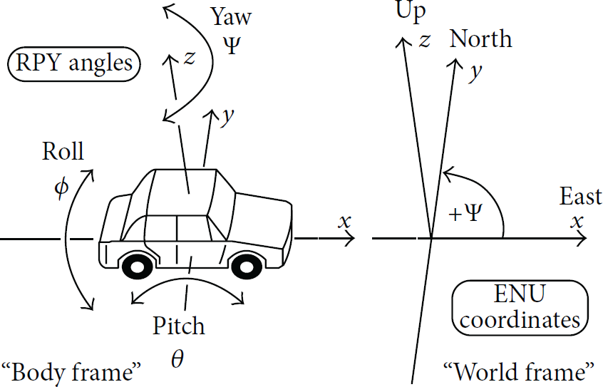
Roll-pitch-yaw angles of cars and other land based vehicles [10].
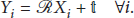
When the vehicle moves to a goal position, there is an amount of movement, as a translation matrix
In this paper, we use a stereo camera as a vision sensor, which consists of two cameras fixed at the same height with a certain distance between them. This sensor uses the triangulation property that if a point in the real world is at a certain distance, then the left and right cameras measure a certain difference in pixels at the same height. More information on this is provided in Richard and Zisserman [11]. There is an intrinsic matrix of the stereo camera with a precalibration process, which means that if each point is measured in the image sensor with u, v, and a value of d, which is the difference between the left and right cameras, each location in an image can be directly transformed into a position in the world coordinate system. Moreover, if the position between the previous and the current image can be determined, an advantage can be obtained in the ego-motion estimation using four consecutive images: left-current, right-current, left-previous, and right-previous. This advantage can be used immediately in 6DoF ego-motion estimations, such as for an automobile.
To estimate ego-motion, it is necessary to gain observation data while the mobile platform is moving. We define these points in this case as follows. The static-rigid points set of the 3D world coordinates for the previous image and the current image are described as
However, there is a sensing error, which is converted into an image-processing error in real environments. Thus, we define a maximum likelihood (ML) method to minimize the error problem in [12, 13]

Simply, to proceed to the 6DoF ego-motion estimation requires selecting features with detection and tracking and then minimizing the error with the optimization process of (2).
In this paper, the detection method of selecting a feature and the tracking method are described in detail. For more information on these methods, see [4]. We used the feature detection and tracking of Ferraz et al. [7].
In the following sections, the ego-motion estimation method that is commonly used in vehicles is described. Then the proposed method is explained to improve a problem using that method.
An algorithm for ego-motion estimation that uses a stereo camera as a vision sensor is described as follows [1, 5].
Algorithm 1.
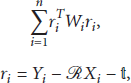
A predetermined number (N) of features are selected randomly. A least-square estimation is run with the selected features. Selecting features is very important at this stage, because if features are lopsided in the image, the estimation will increase the error. To solve this problem, they are selected equally for an entire image by dividing it into fixed blocks and picking a certain number of features in a block, so-called “bucketing” [14]. Each feature position of the previous image is predicted by applying the estimated motion values of 6DoF obtained in Step (1), and then each error of the features is calculated by comparison with the current image's feature position. The error to be used at this time is from (2). To minimize this error, translation vector where Here, the rotation matrix is a nonlinear problem. To solve this, a linearization is applied using a first-order Taylor expansion according to roll (ϕ), pitch (θ), and yaw (ψ) angle. More detailed procedures are described in [15, 16]. Equation (4) is the result of linearization:
where Here, Σ is the covariance value; The iterative operation is repeated until the value of the total error obtained from Step (2) is below a fixed threshold value (< Features are decided to be outliers if they have larger errors (>
β
) of reprojection with the estimated motion values obtained in the process of Steps


The algorithm above is commonly used in ego-motion estimations with a vision sensor method. There are also many other algorithms regarding this problem [3, 4].
3. Proposed Method
In this section, we discuss the image-processing problems in ego-motion estimation using a vision sensor, and then we propose an improved estimation method to solve problems with a moving platform. The following difficulties are encountered in ego-motion estimation of a moving vehicle using a vision sensor. It is difficult to extract an exact feature from an image that is blurred due to acquiring input images when the vehicle is moving at high velocity. Hence, the errors in optical tracking of the same feature between the previous and current image and of the disparity in matching between left and right images increase. Moreover, there may be search space limitations in finding the same features in the left and right and previous and current images in image processing with more outliers at higher velocities.
Thus, to address these problems, we propose a fusion method using a vehicle sensor, such as a relatively accurate vehicle encoder and the wheels. First, measurement data from the vehicle sensor are 2D data for the velocity and yaw rate. It is difficult to use this directly for 6DoF estimation using only these data. In this paper, we solve this problem by generating virtual points. The detailed algorithm process is as follows.
Algorithm 2.
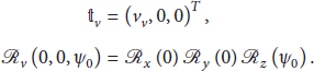
To generate virtual points, use a fixed distance before the previous image in front of the vehicle. In this paper, we empirically generated two points, A new rotational matrix Two virtual points are moved to the current image as Algorithm 1 proceeds with the virtual points and (8), described below, using a weighting value.

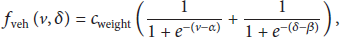
In this paper, so that fusion takes place, the process of the algorithm in Step (2) is as described in Algorithm 1. Generally, when the vehicle is in a highly dynamic situation, at more than 30 kph velocity or over a 20° incline, such as when performing a U-turn, the vision sensor becomes more inaccurate. Then, we assume that the vehicle sensor is more accurate than the vision sensor in these situations. Now, we propose a fusion method where the weighting value of the vehicle sensor is higher than the weighting value of the vision sensor when the vehicle is in such a dynamic state. This means that we differentially use the different properties between the different sensors. In detail, (8) is modified from (5), as follows:

4. Experiments
We used a KITTI open data set to show the superiority of the proposed method. In this data set, the single experimental vehicle in Figure 2 is equipped with a mono camera, a stereo camera, a laser scanner, a GPS, and the IMU. These data were gathered in Karlsruhe, Germany [17–19].

Experimental vehicle fully equipped with sensors.
Figure 2 shows the experimental vehicle. Data were obtained according to a fixed period with a time stamp by the experimental vehicle, and each measured data set is stored in a file.
Figure 3 shows an example of the acquired images in a KITTI data set. The data set comprises typical data measured in a medium-sized German city and includes various road users, such as pedestrians, bicycles, and vehicles in urban and rural environments. The source code for ego-motion estimation that was used in this paper was developed by Geiger [9, 20]. This code used the stereo camera as the vision sensor and was developed for robust estimations for a vehicle platform. In this paper, it was further developed with MS Visual Studio based on Geiger's code. Then, an evaluation was made using the open code that had been published to evaluate it in the same manner with the KITTI open data set.

Examples of captured images in the KITTI data set.
Figure 4 shows the results of feature tracking, which is used in the ego-motion estimation. The circle is a feature position of the current image; a straight line is a corresponding feature from the previous and the current images. Green points and lines were inliers in the ego-motion estimation process, and the red points and lines were outliers that were not used in the estimation.
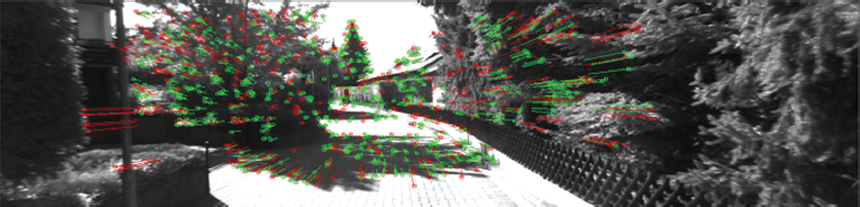
Example of tracking results. Green points and lines are inliers; red points and lines are outliers.
Figure 5 shows the results of compensating the tracking features after estimating the ego-motion step as in Figure 4. Such moving features can be extracted for a moving object by clustering motion vectors.

Results of an ego-motion estimation: an example of a moving vector extracted from the truck in motion using motion parameters.
Figure 6 indicates the trajectory of an experimental result from the KITTI data set. The thick red line represents the ground truth in the evaluation data of less 10 cm, measured with the GPS/IMU system. The blue line shows the relatively higher error of a previous method. The green dotted line is the method proposed in this paper. The results are more correct than the blue line. In the case of motion estimation with a vision sensor only, the accuracy of motion estimation falls according to the vehicle's dynamic state because of blurring, distortion, and false tracking by the vision sensor. In this paper, we used the information from the vehicle's other sensors to solve these problems when the vehicle's dynamic state increased.
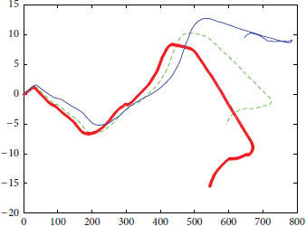
Comparison between ground truth, a previous method, and the proposed method.
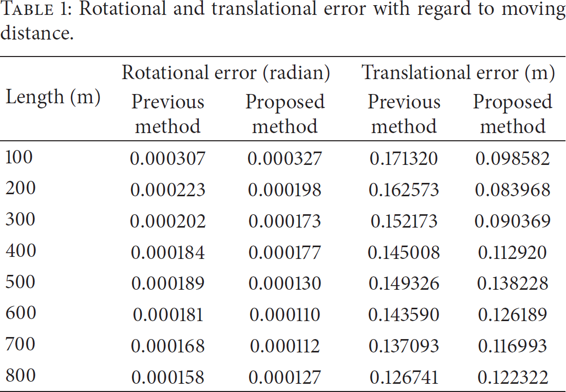
To evaluate our proposed method, an experiment was performed to show its advantages for a total of 10 sequences. Tables 1 and 2 show an evaluation of the experiments. Table 1 shows the results of average error for each 100 m traveled distance. Table 2 shows the results of average error corresponding to the velocity of the experimental vehicle.
Rotational and translational error with regard to moving distance.
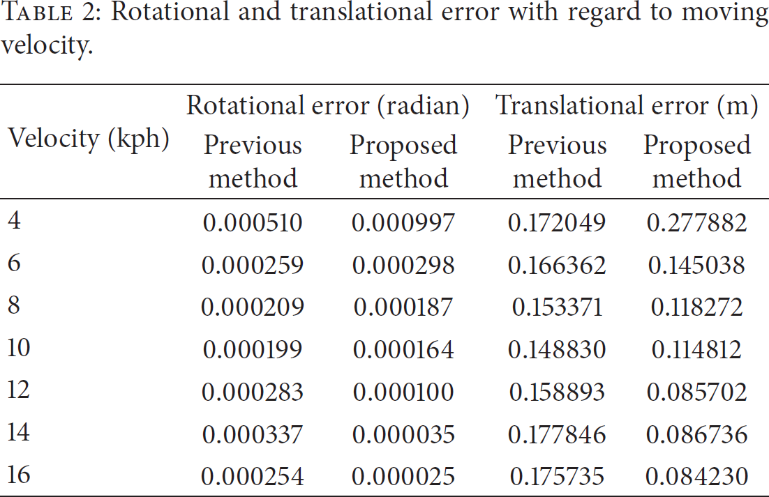
Rotational and translational error with regard to moving velocity.
Depending on the distance that the test vehicle has actually moved, Table 1 shows the average error at each
Table 2 shows the results in accordance with the velocity at which the experimental vehicle was actually moving. These results show that the rotational error of the ego-motion estimation is more robust at 14–16 kph than at a slower 4–6 kph. Our proposed method shows greatly improved accuracy at higher velocities.
Thus, from the results of these experiments, the proposed method shows robustness versus the previous method when the vehicle moves at high velocity.
5. Conclusions
We proposed a method to address problems that occur when ego-motion estimation is made with a vision sensor and a fast-moving platform. The proposed method generates virtual data using the results of the relatively accurate vehicle sensor at high velocity when the vision sensor is relatively inaccurate. It is possible to obtain more robust and accurate results using these data and giving them a higher weighting value. The proposed method was the result of using an automobile platform. In the near future, we plan to advance this fusion method for application to various platforms, such as cellular phones and quadcopters, using multiple sensors to provide more accurate and robust motion estimations.
Footnotes
Conflict of Interests
The authors declare that there is no conflict of interests regarding the publication of this paper.