
Abstract
Transmission links in wireless sensor networks (WSNs) are prone to failure because of breakdown, movement, and energy depletion of nodes. Aiming at node-intensive environment, this paper proposes a highly reliable forwarding model based on virtual nodes (HRVN) in tree-based topology networks. A virtual node (VN) consists of several neighboring physical sensor nodes, which have common parent node and children nodes. Normally, the physical sensor nodes in the same VN forward packets in a load-balancing scheme. When a sensor node in a VN is in failure, the others would take over its forwarding work immediately. Moreover, the internal changes of a VN are transparent to its parent and children nodes. The experiments prove the model can provide load-balance and fast recovery from failure with low cost.
1. Introduction
Wireless sensor network (WSN) has greatly contributed to the progress of health care, environmental monitoring, and other fields. Since sensor node or transmission link failure often happens, the stability of data transmission is a great concern in WSNs. Generally, transmission link failure may influence WSN topologies, which would result in the change of some nodes' IP addresses and forwarding paths. Routing protocol for low power and lossy networks (RPL) [1] is the most popular routing protocol in WSN, which builds a Destination Oriented Directed Acyclic Graph (DODAG) of sensor nodes. In RPL, node failure will lead to the rejoining of some related nodes to DODAG and thereby long waiting for route convergence and recovery.
In this paper, we propose a highly reliable forwarding model based on virtual nodes (HRVN). In HRVN, we assume physical sensor nodes construct a tree topology. A VN consists of several neighboring physical sensor nodes, which have the same parent node and children nodes. Under normal conditions, the physical sensor nodes belonged to the same VN share the forwarding task of packets from or to descendants. In a VN, when a sensor node is out of work, the others would take over its work immediately. Moreover, the internal changes of a VN are transparent to its parent and children.
The remainder of the paper is organized as follows. Section 2 summarizes the related work and HRVN is briefly introduced in Section 3. Section 4 presents design details of the VN, which is the key element in HRVN. Then data transmission and self-healing is described in Section 5, followed by experiments and simulations in Section 6. Finally, Section 7 concludes the paper.
2. Related Work
Sensor nodes have limited storage capacity, battery-power and low computing capacity, and they are always densely deployed in critical environment where replacing broken sensors is hard [2–4]. Consequently, it is necessary that WSN has a highly reliable transmission, lightweight, scalable routing protocol. Lia et al. [5] proposed a Distributed Load Balancing Mechanism (DLBM), which can effectively balance the load around “routing holes” by virtually changing the sizes of holes.
Redundancy strategy of cluster head maintains the normal running of a cluster when the cluster head breaks down or its energy is depleted. It can be divided into two categories, that is, distributed and centralized ones. REED [6] routing protocol based on the former has k cluster sets and several cluster heads in each cluster set. The nodes in every cluster exchange by routing information when the current cluster head breaks down and select the optimal connection node as the backup cluster head from the cluster. However, as all nodes need to maintain the routing information of k cluster heads in this protocol, it may increase the energy consumption and influence the lifespan of networks. Centralized redundancy strategy of cluster head mainly includes K-means [7] and so on. The main feature of them is the current cluster node actively selects backup node and exchanges information with the backup node.
There are many searches on redundancy links. Both Multi-path and Multi-SPEED (MMSPEED) [8] and Multi-Constrained and Multi-path (MCMP) [9] belong to source data packet delivery method of redundancy link. Ren et al. [10] proposed a Traffic-Aware Dynamic Routing (TADR) algorithm based on Dynamic Source Routing (DSR) protocol. The transmission unit of splitting data packet delivery method is smaller than the source data delivery one. Splitting data delivery method avoids over-dependence upon one single link or data packet and this may improve network survivability. However, the splitting and data packet coding processes need a high node computing performance and complex design on routing.
Network reconstruction mainly includes introducing agent nodes and constructing small world networks. The essential is improving node heterogeneity by introducing stronger agent nodes. Moreover, small world networks construct reliable communication links by using long distance connections and mobile agents to improve link heterogeneity. Yang et al. [11] extended the 2-connected problem to a 2-connected Double Cover problem, that is, every network node is covered by two agent nodes at least and the connectivity between agent node and sink node is 2 in backbone networks. Although the fault-tolerance performance is outstanding, this algorithm may spend a great number of agent nodes and has a raising cost.
The RPL [1] is the most widely accepted routing protocol for low-power lossy network. However, it might take a while for RPL to accomplish the routing convergence as the network topology changes.
3. Brief Introduction of HRVN
In order to improve robustness and load-balance of node-intensive WSNs, HRVN is proposed. In HRVN, virtual nodes (VNs) and physical sensor nodes construct a tree topology. Firstly, we give the definition of virtual node as follows.
Definition 1 (virtual node, VN).
VN consists of m (
VN is transparent to the parent node and children nodes since VN may include one or more physical sensor nodes. Without a special statement, each VN includes 2 physical nodes in this paper. As shown in Figure 1, VN1 consisting of Node2 and Node3 provides the forwarding service of the traffic from or toward Node4 to Node9. Node1 and Node4 to Node9 are not interested in which nodes construct VN1. Normally, Node2 and Node3 share the forwarding work according to IP addresses of descendants, which is the source IP of upstream packets or the destination IP of downstream packets. In Figure 1, it is supposed that Node2 forwards traffic of Node4 to Node6 while Node3 works for Node7 to Node9. If Node2 becomes invalid, Node3 would take over Node2's work and provide forwarding service for Node4 to Node9. Furthermore, Node4 to Node9 and Node1 do not perceive the failure of Node2 as they always send messages according to the IP and MAC addresses. Therefore, HRVN has the ability of fast self-healing upon node failure. All nodes in VN need to store the same routing entries with each other for redundant backups. This model can improve the speed of self-healing and enhance the robustness of WSN subnets. Furthermore, since Node2 and Node3 work for the same number of children nodes when both nodes in VN work normally, HRVN achieves an excellent load-sharing performance.
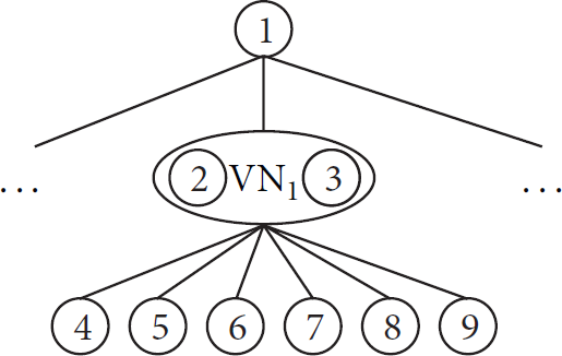
Layer structure in HRVN.
4. HRVN Design
In this section, we give a detailed description of HRVN. For a clear presentation, the symbols that are used throughout the paper are listed in Notations.
4.1. Hierarchical Address Structure
In HRVN, the physical sensor nodes in the same VN have the same forwarding entries. If we use traditional routing protocols such as RPL in a high-density WSN, there may be a large redundancy of forwarding entries. In order to save the storage cost, we use a hierarchical address structure based on the address aggregation towards root node [12]. In this structure, IP addresses of nodes in any individual subtree can be aggregated to one IP prefix.
Definition 2 (Descendant Address Range, DAR).
DAR is an IPv6 network segment. Every node has a specific DAR, which covers the addresses of its descendants. For instance, the DAR of Node4 in Figure 2 is 2001:0002:0003:0/112, and the address of its child Node8 (2001:0002:0003:0001) is included in Node4's DAR.
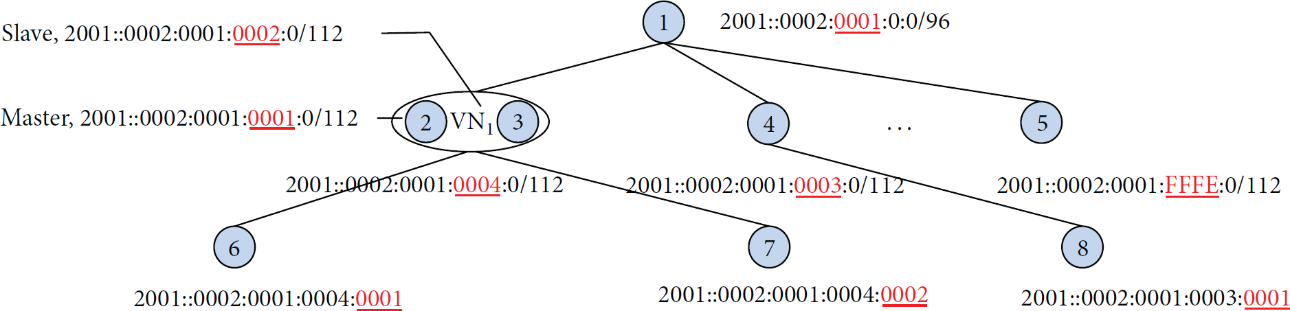
Hierarchical address structure in HRVN.
Definition 3 (layer bits, LBs).
LB of a node is several continuous bits in its IPv6 address excluding its parent's DAR. In this paper, the length of the layer bits is 16.
In the hierarchical address structure, Node i generates an address for each child, which is composed of Node i 's DAR and a new LB. Therefore, we could obtain the parent-child relationship via the addresses. In this way, every node only needs to store the forwarding entries of its parent and children.
Take Figure 2 as an example. VN1 consists of Node2 and Node3. Node6 and Node7 are VN1's children while VN1's parent is Node1. Node1 with DAR 2001::0002:0001:0:0/96 generates addresses for Node2 and Node3, that is, 2001::0002:0001:0001/112 and 2001::0002:0001:0002/112, respectively. In VN1, after the master election process, master Node2 informs Node1 to assign an address to VN1 and uses VN1's DAR to generate its children's addresses. Then VN1 only stores the forwarding entries to its parent Node1 and children Node6 and Node7. In order to find the parent-child relationship, taking Node7 with address 2001::0002:0001:0004:0001 as an example, we remove Node7's LB from its address and get 2001::0002:0001:0004:0000, which should be Node7's parent's address. Thus, in Figure 2, VN1 is Node7's parent.
4.2. VN Construction
When a node turns on, it finds its neighbors and then its parent and brothers. VN construction includes three processes, namely, neighbor node discovery, parent node discovery, and VN maintenance. The relevant messages in these processes are listed in Table 1.
Messages in HRVN.

In HRVN, the neighbors of a node are nodes in the communication range of the node, whose layers are
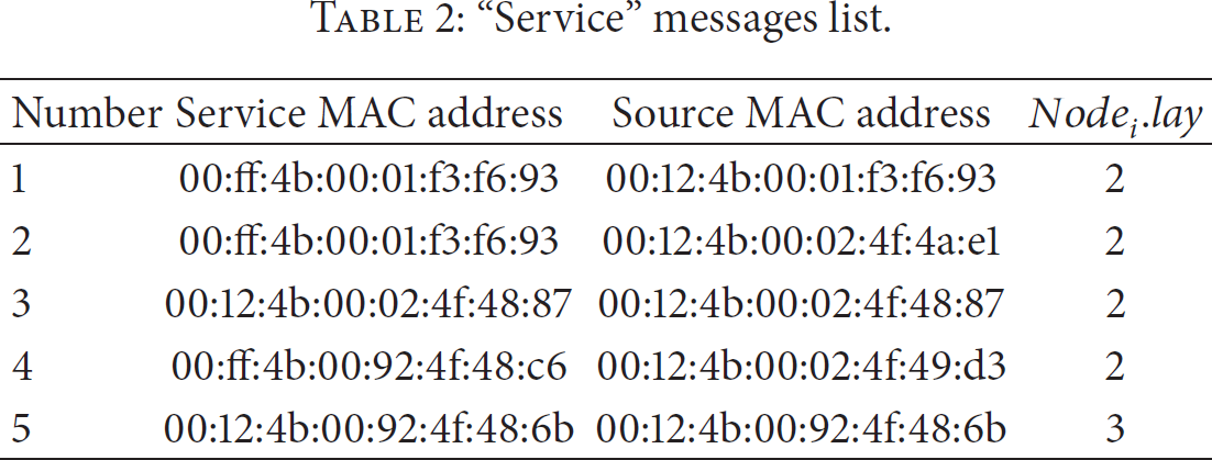
During the parent node discovery process, the nodes in the tree send “service” messages to inform others to join them. For each node in a VN, the service MAC address in its “service” message is the MAC address of this VN. While for a node that is absent in VNs, the service MAC address is its own MAC address. Once the node gets the “service” messages, it filters out those messages having the minimum layer. If there are two “service” messages having the same service MAC address but different source MAC addresses, it means they are from two nodes in the same VN and this VN is an alternative parent. VNs are more likely to be selected as parents to provide robust data transmission.
Table 2 lists the “service” messages received by a node. After filtering the messages having the minimum layer, there are 4 messages left, that is, number 1, number 2, number 3, and number 4. It is observed that number 1, number 2, and number 4 “service” messages are from VNs, while number 3 is from a physical node. Furthermore, the VN with MAC address 02:ff:4b:00:92:4f:48:c6 cannot be selected as an alternative parent, because there is only one message from this VN. Therefore, the node selects the VN whose MAC address is 00:ff:4b:00:01:f3:f6:93 as its parent and sends the “connection request” to the VN.
“Service” messages list.
Take the Node f as an example. The process after Node f receiving the “connection request” messages is described in Algorithm 1.
save the “connection request” messages into a set Req: (1) sort_increace(Req, (2) (3) (4) (5) send “connection request ack” to refuse the nodes in Req; (6) return; (7) (8) assign an address to the sender of Req[k]; (9) send “connection request ack” to agree the request from Req[k] (10) add the sender of Req[k] into Node
f
's forwarding table; (11) remove Req[k] from Req; (12) k++; (13) (14) (15) return;
In HRVN, a node's brothers are those having the same parent node and within the communication range of this node. In the VN maintenance process, a node broadcasts the “hello” message first. And then it finds its brothers from the received “hello” messages. After that, it sends a “pair request” message to the brother having the most common neighbors. Take Node n as an example. The VN maintenance process is described in Algorithm 2.
receive the “Hello” messages and save them into a set (1) (2) save the senders of messages in (3) (4) (5) return; (6) (7) sort_decrease( (8) (9) (10) (11) send a “pair request” message to (12) (13) (14) k++; (15) return; (16) (17) return; (18) (19)
After a node receives the “pair request” messages, it sends the “pair request ack” message to the node which has the most common reachable nodes. Take Node n as an example. The process after the node received the “pair request” is described in Algorithm 3.
receive the “pair request” messages: (1) (2) save the received “pair request” messages into (3) (4) sort_decrease( (5) (6) (7) (8) save (9) run Algorithm 4; (10) send “pair request ack” to agree the request from (11) (12) k++; (13) return; (14) (15) (16) send “pair request ack” to refuse all the nodes who sent “pair request” to (17) return; (18)
(1) (2) select (3) (4) select (5) (6) (7) select (8) (9) select (10) (11) (12) send the election result to (13) return;
Before a node sends the “pair request ack” message to its brother, it needs to select a master and informs its brother the selection result via “pair request ack” messages. Take Node b as example. The election process is described in Algorithm 4.
After the master election process, the master node copies its own MAC address and uses FF to replace the second byte of the MAC address to generate the VN's MAC address. Then the master informs its parent to assign the IP address to VN. The detailed process of address assignment is described in Section 4.1. Thereafter, the master node synchronizes the VN's MAC/IP addresses and forwarding entries with slave nodes. In addition, the nodes in a VN share the forwarding work according to the rules, which will be discussed in Section 5.
5. Data Forwarding and Self-Healing
Under usual conditions, both nodes in the same VN work fine. Which node forwards a packet in the VN is determined by the IP addresses of the packet. When the downstream packets are forwarded via a VN, the destination IP addresses of the packets will be analyzed. On the contrary, the source IP addresses of upstream packets will be analyzed. Both the master and the slave in the same VN can receive the packets whose destination MAC addresses belong to the VN. However, the master only processes the packets whose LB is 1, while the packets whose LB is 0 would be discarded at the link layer. Meanwhile, the slave only processes the packets whose LB is 0. In this state, either the master node or the slave node undertakes approximately half of the VN's forwarding traffic. As shown in Figure 3(a), VN1 consists of the master Node2 and the slave Node3. Node4 and Node5 are sending packets to node 1 via VN1. According to the IP addresses of Node4 and Node5, we know the LBs of Node4 and Node5 are 0001 and 0002, respectively. Therefore, Node2 only forwards the packets from Node4 to Node1 and discards the packets from Node5.

Self-healing after link failure.
After VN is constructed, the master and slave nodes send “heartbeat” messages to each other indicating their respective statuses. If Node2 is broken, as shown in Figure 3(b), Node3 changes its forwarding strategy and processes all the packets received regardless of the LB. In this way, HRVN provides a fast recovery from node failure for data transmission.
In VN, a node can take over its broken brother's work. However, to construct a new VN, great efforts are needed to find other appropriate nodes. Figure 4(a) shows the adjacency relationships and the parent-child relationships of the nodes. If Node2 of VN1 is broken, as shown in Figure 4(b), Node3 will look for another brother node to construct a new VN. According to Algorithms 2–4, both Node 6 .reach_list and Node 8 .reach_list contain all the nodes in M 3 .son_list, and then Node3 will select Node6, whose reach_list is shorter, to construct the new VN1 as shown in Figure 4(c).
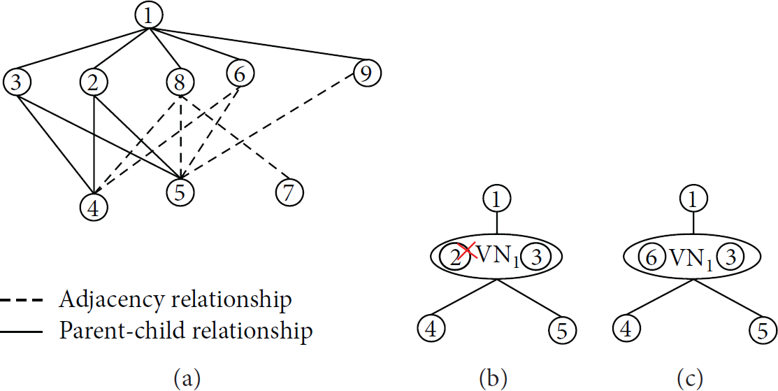
Case 1 of finding a new brother node.
In the process of VN reconstruction, the number of VN's children nodes may increase. In Figure 5, VN1 consists of Node2 and Node3. Node4 and Node5 are VN1's children nodes. Meanwhile, Node6 and Node7 are children nodes of Node3 rather than VN1. When Node2 is broken, Node3 will select Node8 to construct the new VN1 according to Algorithms 2, 3, and 4. At this time, the new VN1 possesses additional children nodes, that is, Node6 and Node7.

Case 2 of finding a new brother node.
After that, the master will be reselected as described in Algorithm 4 and synchronizes its own forwarding entries, parent node info, and the new VN's IP/MAC addresses with its new brother node.
6. Performance Evaluation
HRVN has a distinct advantage in routing table storage compared with RPL. Due to the address assignment and routing protocol HRVN uses, a node achieves the forwarding work by only storing the forwarding entries of its children nodes and parent node. For ease of description, we use a complete k-tree with a height of n as prototype. The root node is at layer zero, the number of the physical nodes at the first layer is k, and the nth layer has
At the nth layer, there are up to 
In RPL, except for the leaf nodes, all the physical nodes have to store both the forwarding entries of its parent and descendants. Leaf nodes only need to store the forwarding entries of their parent nodes. Meanwhile, the root node stores 
We analyze the total number of the entries that RPL and HRVN need to store at different layers when k is taking 2, 3, 4, and 5. As shown in Figure 6, although the VN uses the forwarding entries redundancy to ensure highly reliable data transmission, the increase of forwarding entries' storage is insignificant. And with the increase of k, HRVN's advantage in forwarding entries' storage is more obvious. At each layer, the number of forwarding entries a node stores in HRVN is more uniform than in RPL.
The storage of routing entries.
Assuming the physical node's failure rate is η and the possibility of failure between nodes is independent, VN's failure rate is 
As shown in Figure 7, the more the virtual nodes on the path, the more reliable the path.

The disconnection rate of the path.
Following the above analysis, VN significantly improves the stability of data transmission links. Assume VN's contribution ratio is the number of nodes transmitting data via this VN. Then in an n-layer complete k-tree, if a VN is at the jth layer 
In HRVN, as the 0th layer is the root node and the bottom nodes are at the 4th layer, we only consider the contribution ratio between the 1st layer and 3rd layer. As shown in Figure 8, the VN at a higher layer has a greater contribution ratio.
Contribution ratio of VN.
We experiment with real sensor nodes to evaluate the performance of HRVN, and the detailed parameters of the sensor nodes are shown in Table 3.
Sensor node's parameters.

In our experiment, we use the MAC address filter to construct a particular topology as shown in Figure 9 and implement HRVN on subtree 1. As leaf nodes Node6 and Node7 send an “echo request” message to Node1 per second, using the wireless sniffer to monitor subtree 1, we can get the packet processing delay and recovery duration.
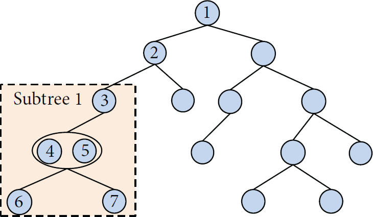
The experiment subtree.
First, we test the processing capacity of VN of different data lengths. Through the Wireshark, we set
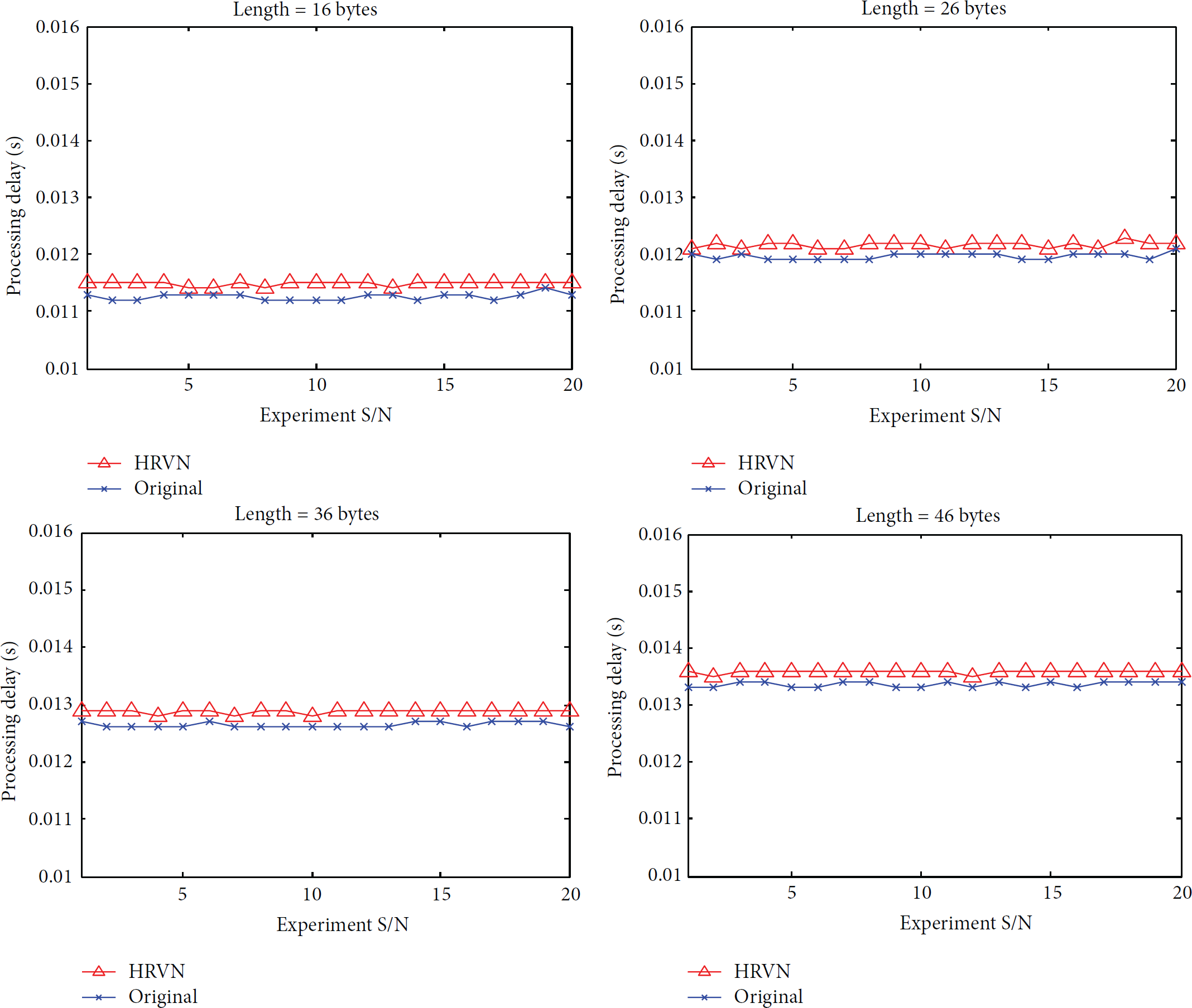
The processing capacity of different data lengths.
Once the forwarding tree is built, the leaf nodes start to send messages to the root node. We randomly shut down one of the leaf nodes' parent nodes in subtree 1. For example, in the experiment, we first shut down Node4 in subtree 1. When Node5 starts to forward the messages from both Node6 and Node7, it means the link has been recovered. In order to facilitate the test, the brother nodes send a “heartbeat” message to each other per 2 seconds. However, the “heartbeat” frequency can be adjusted flexibly according to the bandwidth, energy, and the processor capacity. If the node has missed the “heartbeat” for 4 consecutive times, it means this node's brother is broken. According to the previous set, the recovery duration is between 6 and 8 seconds theoretically. We test the recovery duration with c children nodes and retest for 20 times for each amount. In Figure 11, the results show that the number of children nodes does not affect the recovery time of HRVN and the recovery time is within the theoretical value. In summary, HRVN achieves an excellent fast-recovery and load-balance data transmission with a low cost.

The recovery duration with different quantity of children nodes.
7. Conclusion
In order to improve robustness and load-balance in node-intensive WSNs, we propose HRVN in this paper. In HRVN, VNs and physical sensor nodes construct a tree topology, and a node only needs to store the forwarding entries directly to its children and parent nodes. Furthermore, the IPv6 addresses of nodes or VNs aggregate highly in each subtree. HRVN provides a load-balancing and failure-backup scheme based on VNs. The analysis shows that HRVN's storage consumption of forwarding entries is less than RPL. Moreover, in HRVN, the storage consumption of node forwarding entries is only related to the number of its children and parent nodes. Therefore, the number of forwarding entries of a node will not increase as its layer increases. In a VN, the physical sensor nodes share the forwarding work according to the LBs of their descendants. However, when a node becomes invalid, the others will take over its work. We conduct experiments with real sensor nodes to evaluate the performance of HRVN, the results of which show that HRVN achieves an excellent load-balance and fast-recovery data transmission with a low expense on forwarding capacity. However, the address assignment of HRVN may cause a waste of IP addresses. We leave exploring the callback mechanism of IP addresses as the future work.
Footnotes
Notations
Conflict of Interests
The authors declare that there is no conflict of interests regarding the publication of this paper.
Acknowledgments
This research is supported by the National Natural Science Foundation of China (nos. 61373161, 61272446) and Science & Technology Project of Beijing Municipal Commission of Education (no. KM201410028015).