
Abstract
This paper presents an energy harvesting wireless sensor network (EHWSN) architecture designed for use within an astronaut's space suit. The contribution of this work spans both physical (PHY) layer energy harvesting transceiver design and low power medium access control (MAC) solutions. The architecture consists of a star topology with two types of transceiver nodes: a powered gateway radio (GR) node and multiple energy harvesting biosensor radio (BSR) nodes. To demonstrate the feasibility of an EHWSN at the PHY layer, a representative BSR node is implemented. The BSR node is powered by a thermal energy harvesting system (TEHS) which exploits the difference between the temperatures of a space suit's cooling garment and the astronaut's body. It is shown that, through appropriate control of the duty cycle in transmission and receiving modes, it is possible to operate with less than 1 mW generated by the TEHS. This requires ultralow duty cycle which complicates MAC layer design because a BSR node must sleep for more than 99.6% of overall operation time. The challenge for MAC layer design is the inability to predict when the BSR node awakens from sleep mode due to unpredictability of the harvested energy. Therefore, a new feasible MAC layer design, GRI- (gateway radio initialized-) MAC, is proposed and analyzed.
1. Introduction
Wireless sensor networks (WSNs) offer new ways for technology to interact with our physical world. The building blocks for WSN are nodes that possess sensing capabilities to measure/detect physical quantities (e.g., movement, chemicals, and body temperature) and associated low power radio technologies to transmit that data. With the growth in embedded computing, these nodes are equipped with processing units for computation as well [1].
While most existing WSNs use a battery as a power source, there is growing interest in harvesting energy to design a self-powered sensor node with a significantly longer lifetime [2–4]. Energy from the environment can be converted into electrical energy using various energy harvesting (EH) techniques. Although the output power from an energy harvesting system (EHS) is usually extremely low (uW~mW) and varies over time, with the development of ultralow power electronics and energy storage techniques (e.g., low leakage supercapacitors), energy harvesting wireless sensor networks (EHWSNs) are getting closer to reality [5–9]. However, the efficiencies achieved and the mode of energy harvesting available impose unique constraints on both hardware and software design associated with each network. Therefore, a one-size-fits-all approach to design of such networks will result in suboptimal performance. In this paper, we attempt to address some fundamental issues in EHWSN by designing and analyzing the feasibility of new PHY and MAC layer custom designed for one such unique environment, an astronaut body area network.
The physical and mental health of astronauts on deep space missions will be challenged by the harsh operating environment. Various devices have been developed to track and predict an astronaut's health status in order to both maximize their working efficiency and ensure their safety [10]. Wirelessly networking these devices to create a body area network will offer the capability to track the health of the astronaut in real time [11]. However, powering the sensors housed inside an oxygen-rich pressured spacesuit with batteries presents safety concerns. Therefore, the astronaut body area network offers a perfect test case for evaluating the feasibility of ultralow power energy harvesting based network design.
While typical energy harvesting sources may include light (solar) [12], vibration [13], or radio frequency [9], these sources may not be available within space suits and missions. However, astronauts typically wear a cooling garment that creates a temperature differential that can be exploited for harvesting energy. While a preliminary study in [14] finds that thermoelectric generation is in fact the most suitable energy harvesting method for using inside a spacesuit, the method has extremely low output power (<1 mW). As mentioned, this ultralow power constraint imposes challenges to both the PHY and MAC layers of the EHWSN that prevents the use of typical standards such as Bluetooth and Zigbee. Hence, new approaches are needed.
In this paper, our aim is to develop an ultralow power energy harvesting wireless sensor network that is custom designed to fit the constraints. The goal of the sensor network is to obtain biological signals from the astronaut and transmit the data to a central processor/computer housed within the space suit backpack for further analysis or relay to a base site. The EHWSN designed in this work, therefore, adopts a star topology, in which a gateway radio (GR) (housed in the backpack) works as central node and multiple biosensor radios (BSR) work as subnodes. A subtle difference from traditional EHWSN in which all the nodes are considered energy harvesting nodes is that the GR node is powered by the backpack battery of the space suit and thereby not energy constrained. The BSR nodes, however, are very constrained in their available power and must operate at very low duty cycles to successfully function.
To demonstrate the feasibility of this EHWSN at the PHY layer, a representative BSR node is designed and described in this paper. The BSR node is powered by a thermal energy harvesting system (TEHS) which exploits the 10-to-20-degree difference between the temperatures of a space suit's cooling garment and the astronaut's body. It is shown that, through appropriate control of the duty cycle in transmission and receiving modes, it is possible for the transceiver to operate with less than 1 mW power generated by the TEHS even when the transceiver draws much higher power when active. A supercapacitor, energy storage of TEHS, acts as an energy buffer between TEHS and power-consuming units (processing units and transceiver radio). The supercapacitor charges when a BSR node is in sleep mode and discharges when the node is active. The node switches from sleep mode to active mode whenever the supercapacitor is fully charged. A voltage level monitor detects the system's energy level by measuring the voltage across the supercapacitor. Since the power generated by the TEHS is extremely low (less than 1 mW) and a BSR node consumes relatively high power (up to 250 mW) during active mode, a BSR node must work under an extremely low duty cycle (approximately 0.4%). This ultralow duty cycle complicates MAC layer design because a BSR node must sleep for more than 99.6% of overall operation time. The resulting challenge for MAC layer design is the inability to predict when the BSR node awakens from sleep mode due to limited availability/predictability of the harvested energy.
While our solution is specific to the case study of astronaut body area network, it is important to note that the design principles are general and can be used as a guide for other ultralow power energy harvesting networks.
The paper is organized as follows: In Section 2, we discuss the design of the thermal energy harvesting system; Section 3 provides information on both hardware and software aspects of our low power transceiver design. Sections 4 and 5 are devoted to the discussion of the proposed MAC layer and its performance, respectively. Conclusions and possible future directions are highlighted in Section 6.
2. Thermal Energy Harvesting System Design
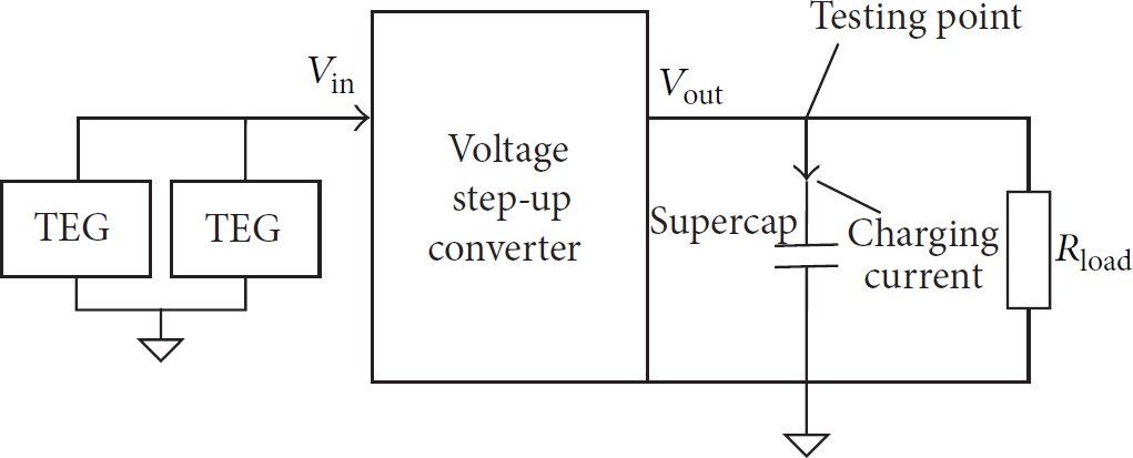
Energy harvesting has been an active field for over a decade and many investigations have been carried out using different energy sources and harvesting methods [15–20]. A thermal energy harvesting system (TEHS) is used in this work because of the unique environment inside the space suit, where light and radio waves are not significant sources and motion and vibration cannot be assured to exist consistently. To fit this novel environment with its available interior cooling garment source, a custom TEHS system was built consisting of a thermal electric generator (TEG), a voltage step-up converter, and a supercapacitor (50 mF) as shown in Figure 1.

Thermal energy harvesting system.
The thermal electric generators used are Peltier devices operated in reverse mode. Several devices were tested for the application since limited information was available on output voltage and current when operated as a TEG. A graph of measured open-circuit voltage versus temperature for three models is shown in Figure 2, and additional data on associated short-circuit current output can be found in [14]. When operated with one side on a subject's arm and the other on a room-temperature plate, the devices were capable of supplying between 200 and 400 microwatts each, producing 50 to 70 mV and approximately 4 to 6 mA.
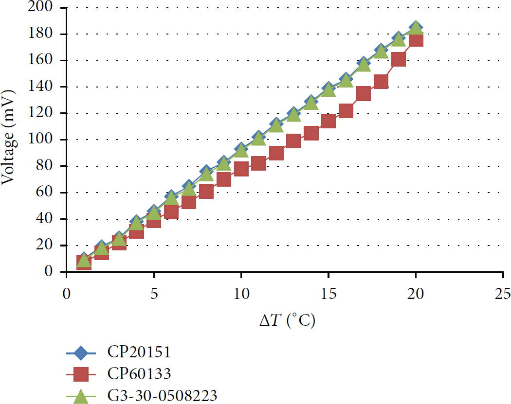
Measured TEG output voltages versus temperature difference. (From [14]).
Because of the low voltages involved, two TEGs were placed in series in the system. Details of the TEHS circuit implementation are shown in Figure 3 and the major components of the system are listed in Table 1. While the TEGs are electrically in series as shown, mechanically they are in parallel so that their temperature drive is not reduced and twice the power is available. The TEGs are interfaced to a Linear Technology LTC3108 ultralow voltage DC to DC converter as shown in Figure 3 to generate nominal 4 to 5 V output. With this configuration and the selected Coilcraft LPR6235-752SMR 1 : 100 transformer shown in the parts list of Table 1, the system can start up with as low as 30 mV (15 mV each). However, since charging time is important, using two series-connected TEGs provide both faster and more reliable charging if the temperature difference is low in a particular usage scenario. Measured efficiency of the circuit of Figure 3 was in the range of 30%, which is consistent with the LTC3018 datasheet performance information, for the nominal 50 to 70 mV TEG output level and the selected 1 : 100 transformer.
Major components used in TEHS.


Schematic of TEHS circuits.
Since a thermal electric generator (TEG) needs a temperature differential to generate electrical power [21], our approach is to exploit the difference between astronaut's body temperature and the cooling garment that is worn. However, the key challenge is to ensure that there is adequate physical contact between the TEG terminals and the body/cooling garment. A solution to this problem is shown in Figures 4 and 5, in which a model node is designed to provide maximum thermal flow. On the top side, a 0.019-inch-thick copperplate is bent into a U shape to bypass the motherboard (MB), connecting the cold side of the TEG thermally to an ice bag (simulating the cooling garment temperature sink). On the opposite side of the white radio housing, a copperplate contacts the body to the bottom side of a daughterboard (DB) (see Figure 6) circuit board and vias filled with thermal paste connect thermally to the hot side of TEG. Since copper has very high thermal conductivity (401 W/(mK)) and is reasonably thick, very little temperature is dropped when energy flows through these interfaces, maximizing heat dissipation in the TEG elements and hence maximizing harvested energy.

Testing setup model.

Real testing setup.

Daughter board.
Figure 7 shows the test setup used to assess the thermal energy harvesting capabilities of the TEGs in this arrangement. A load resistor was placed across the supercapacitor to determine average power available with 100% duty cycle operation. One of three conditions must happen when adjusting this load resistor value: (1) the voltage across supercapacitor decreases, indicating that load power is greater than TEHS overall output power; (2) the voltage increases, indicating that load power is less than TEHS overall output power; (3) the voltage remains stable, indicating that load power equals TEHS overall output power. The resistor value which keeps the voltage remaining stable is recorded in Table 2 and the TEHS overall output power is calculated by
Overall output power.

Output power measurement setup.
Additional measurements were made on the radio used in the research endeavor [14], and the power consumption during active modes (transmit data) was found to be approximately 250 mW. From Table 1, it is evident that since the TEG provides only 0.9 mW power, the operation duty cycle must be less than 0.4%. To make the system run under this extremely low duty cycle, we needed to develop a custom hardware system (Section 3) which can operate with extremely low power consumption during sleep mode (approximately 1 μA) and design a feasible MAC layer (Section 4) which works properly with this extremely low duty cycle.
3. Transceiver Design
The transceiver motherboard inside the case shown in Figure 4 is a custom designed unit operating at UHF frequencies (400 MHz). It is built around a custom single-chip UHF transceiver Radio Frequency Integrated Circuit (RFIC) combined with a low power microcontroller and FPGA on the main board [10]. These elements interface to the antenna, biosensor electronics, and the TEG elements on the daughterboard [14]. Full custom software then manages the hardware elements to achieve the extremely low duty cycle operation needed.
3.1. Hardware
The motherboard is shown in Figures 8 and 9 mated to a daughterboard. The motherboard contains two regulators, a microcontroller (μC), an RFIC, and a field programmable gate array (FPGA). All major components are given in Table 3.
Major ICs on motherboard.


Top view of motherboard mated to daughterboard.

Block diagram of motherboard (KANDB: K-State-NASA Body Area Network Development Board).
3.1.1. Regulators
Two regulators in the motherboard work with input voltage range spans of 3.7 V to 5.0 V delivered from the daughterboard supercapacitor. Regulator 1 converts incoming voltage to 3.3 V to power the μC, the FPGA, and the RFIC. Regulator 2 converts incoming voltage to 1.5 V to power the FPGA core logic. Both regulators contain an enable pin that activates or deactivates the output voltage. The 3.3 V regulator is active constantly to power the μC and draws a quiescent current of approximately 2 μA [22]. The enable pin of the 1.5 V regulator is controlled by the μC to power down the FPGA during sleep.
3.1.2. μC
Three main tasks of the μC include operating as a power manager, functioning as an analog to digital converter (ADC), and working as a data storage buffer. The μC can individually turn the power supply on or off for each component (Regulator 2, RFIC, FPGA, and sensor) on the BSR node. When acting as a power manager, the μC places the board in different modes according to the energy level of the supercapacitor on the daughterboard. The μC uses its built-in analog to digital converter (ADC) to monitor the voltage across the supercapacitor on the BSR daughterboard and shuts down other systems when the voltage approaches the lower voltage limit of the regulator ICs. When energy harvesting has restored enough charge on the capacitor the regulators are enabled and the μC manages sampling of the biosensors and operation of the radio transceiver. At this point it is acting as an ADC and a storage buffer.
3.1.3. FPGA
The motherboard's FPGA has four main functions: data processing (e.g., compression), packet formation, bidirectional communication with μC, and RFIC programming. In receive mode, the FPGA also serves as the digital demodulator for the RF functions.
3.1.4. RFIC and Energy Detection
The RFIC employs a fractional-N synthesizer used to FSK-modulate incoming data onto a 433 MHz carrier when transmitting. In receive mode, the RFIC delivers a 1-bit oversampled version of its intermediate frequency (IF) signal to the FPGA, which performs FSK demodulation. The FPGA manages the RFIC mode and operating frequencies by setting appropriate values in the RFIC's programmable control register.
3.2. Software
The key challenge for the software is to manage sampling of biosensor data and buffer this data until sufficient energy is available to burst it out at high rate. This subsection overviews the main physical layer actions, while the following section will elaborate the medium access layer issues.
3.2.1. Transmission Mode
The primary functions of the motherboard software include controlling the active mode/sleep mode duty cycle, sampling sensor data, creating data packets, and controlling the RFIC to transmit and receive these packets. In transmit mode, the software operation is described in Figure 10.

Software design overview for transmission mode.
3.2.2. Packet Formats
In wireless communication, data is most often transmitted in the form of packets. Two types of packets are used in this design: data packets (see Figure 11) and command packets (see Figure 12). Each type is formatted to achieve a good tradeoff between performance and data transmission efficiency when operating at extremely low power. Hence, the packet definitions are highly simplified, sacrificing performance to minimize power wherever necessary. In particular, the bit and frame sync sections are significantly shorter than in many standards-based systems.
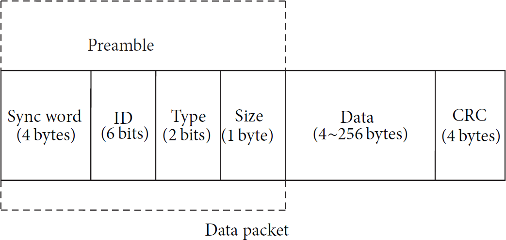
Data packet.

Command packet.
(1) Data Packet. A data packet consists of the following:
4-byte sync word: “010101…” sequence and “111” to indicate the end of the sync word. 1-byte ID and type: 6-bit ID that can define up to 64 BSR nodes and 2-bit type that is always “10” for data packet. 1-byte size: identifies the number of bytes in the “data” (up to 256). 4- to 256-byte data payload. 4-byte CRC.
(2) Command Packet. A command packet consists of the following:
4-byte sync word: “010101…” sequence and “111” to indicate the end of the sync word. 1-byte ID and type and parity check: 6-bit ID that can define up to 64 sensors, 1-bit type that is always “0” for command packet, and 1-bit parity check. 1-byte command and parity check: 7-bit command (up to 128 commands) and 1-bit parity check.
3.2.3. Receiving Mode
The software design of the receiving mode focuses on the processing of incoming data after the demodulation process is performed by the FPGA. FPGA functions are the subject of a parallel research project covering demodulation, bit synchronization, and packet detection [23]. The primary functions of receiving mode software include synchronization of incoming data, detection of the sync word, and packet processing. A block diagram of the steps involved in the reception process is shown in Figure 13.

Block diagram of reception process.
4. MAC Design
In the context of sensor networks, an efficient MAC design can greatly extend sensor lifetime [24]. Currently, there are many “low power” MAC layer designs for WSNs that attempt to obtain high energy efficiency by duty-cycling each node [25, 26]. Duty-cycling nodes between sleep mode and active mode can reduce unnecessary power consumption. In this section, we highlight the key design constraints for our astronaut body area network and propose a new low power gateway radio initiated asynchronous MAC protocol.
4.1. Extremely Low Duty Cycle
Our energy harvesting sensor node has a duty cycle of approximately 0.4%. This duty cycle value is limited by charging current (≈200 μA) from the energy harvesting system and discharging current (≈50 mA) for data transmission. Therefore, in the design of a MAC layer, the sleep mode period of BSR node has to be maintained at least 250 times longer than the active mode period. For example, if a transmit node spends 300 ms to transmit a packet, it must sleep for approximately 1.25 minutes to recover its energy.
4.2. Single and Unpredictable Energy Source
In our energy harvesting system, TEG is the only energy source. The TEG converts thermal energy (due to temperature difference) to electrical energy to power the motherboard. Since the level of contact with the copperplates can vary with the location of the sensor and movement of the astronaut, the generated energy can vary unpredictably at times. So, the MAC design has to account for this unpredictable energy source.
4.3. Star Topology Network
Our network can be considered as a Single Cluster Star Topology Network (SASTN) that consists of one GR node and multiple BSR nodes (Figure 14). In contrast to an ad hoc network, in which every node plays an equivalent role, the GR node is a power-unconstrained node (powered by the space suit) that works as central node to receive all data packets. BSR nodes are power-constrained nodes (powered by energy harvesting system) that work as subnodes to transmit data packets. Therefore, an efficient MAC protocol design should shift the burden of energy intensive tasks to the GR node as best as possible.
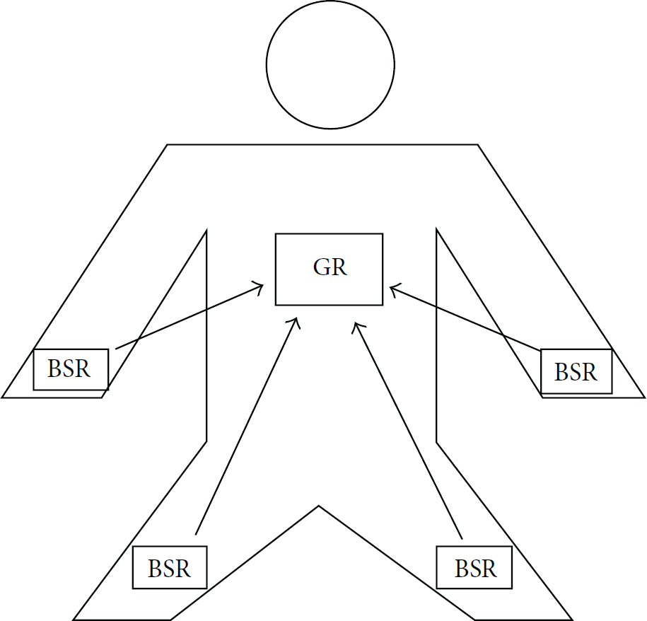
Overview of a star topology network.
4.3.1. GR Initiated Based MAC Layer Design
In this subsection, we describe the proposed GR based MAC (GRI-MAC) which is a receiver initiated asynchronous MAC protocol that can be perceived as a modified version of RI-MAC [27] and X-MAC [28]. In the X-MAC protocol, the sender node sends a series of short preambles to initiate the communication. However, in our proposed approach we use GR node to broadcast beacons to initiate a transmission in GRI-MAC. Additionally, these beacons are sent periodically with a short period. This helps overcoming one of the issues in RI-MAC where the senders suffer from relative long idle listening time.
4.4. GR Node Process
A GR node keeps its radio on in order to periodically broadcast a beacon and detect the channel. GR node's working process is shown in Figure 15. After broadcasting a beacon with a specific node ID, a GR node switches from Tx mode to Rx mode and stays in Rx mode for duration beacon gap to detect any incoming response/packet. If no packet is received during beacon gap, the GR node switches to Tx mode to broadcast a beacon again with another ID. The GR node broadcasts beacons with preset order (ID number from 1 to n) and repeats this process cyclically. During a beacon gap, if a GR node listens to an incoming data packet, the GR node continues in Rx mode until the entire packet is received. When data packet receiving is complete, the GR node sends an ACK command to the transmitting BSR node to indicate a correct reception. Then, the GR node continues to broadcast beacon with the next ID number.

Working process of GR node.
4.5. BSR Node Process
A BSR turns on its radio to listen to beacons whenever the node is ready to transmit a data packet. If no beacon is detected within its minimum listening time (MLT) (MLT length must cover at least two lengths of beacon and one beacon gap length to ensure that at least one entire beacon is detected), this indicates that another node data packet is being transmitted. At this point, the BSR turns to sleep mode for a short period equal to the longest data packet transmission time. After finding a beacon, a BSR node compares the beacon ID with its own ID in order to estimate time of detecting the intended beacon. If the time is greater than twice the Temperature Compensated Crystal Oscillator (TCXO) stabilization time (T_oscillation), the BSR node sleeps for the estimated time. Otherwise the BSR node extends its listening time to detect the intended beacon. When the intended beacon is found, the BSR node begins to transmit a data packet. If the BSR node receives an acknowledgement (ACK) command or detects a low energy level, it goes to a sleep-sampling period to wait for the next transmission cycle. If the BSR node fails to receive an ACK, the system will detect a low energy level, since the BSR node will have no extra energy to resend the data package. The entire working process is shown in Figure 16.
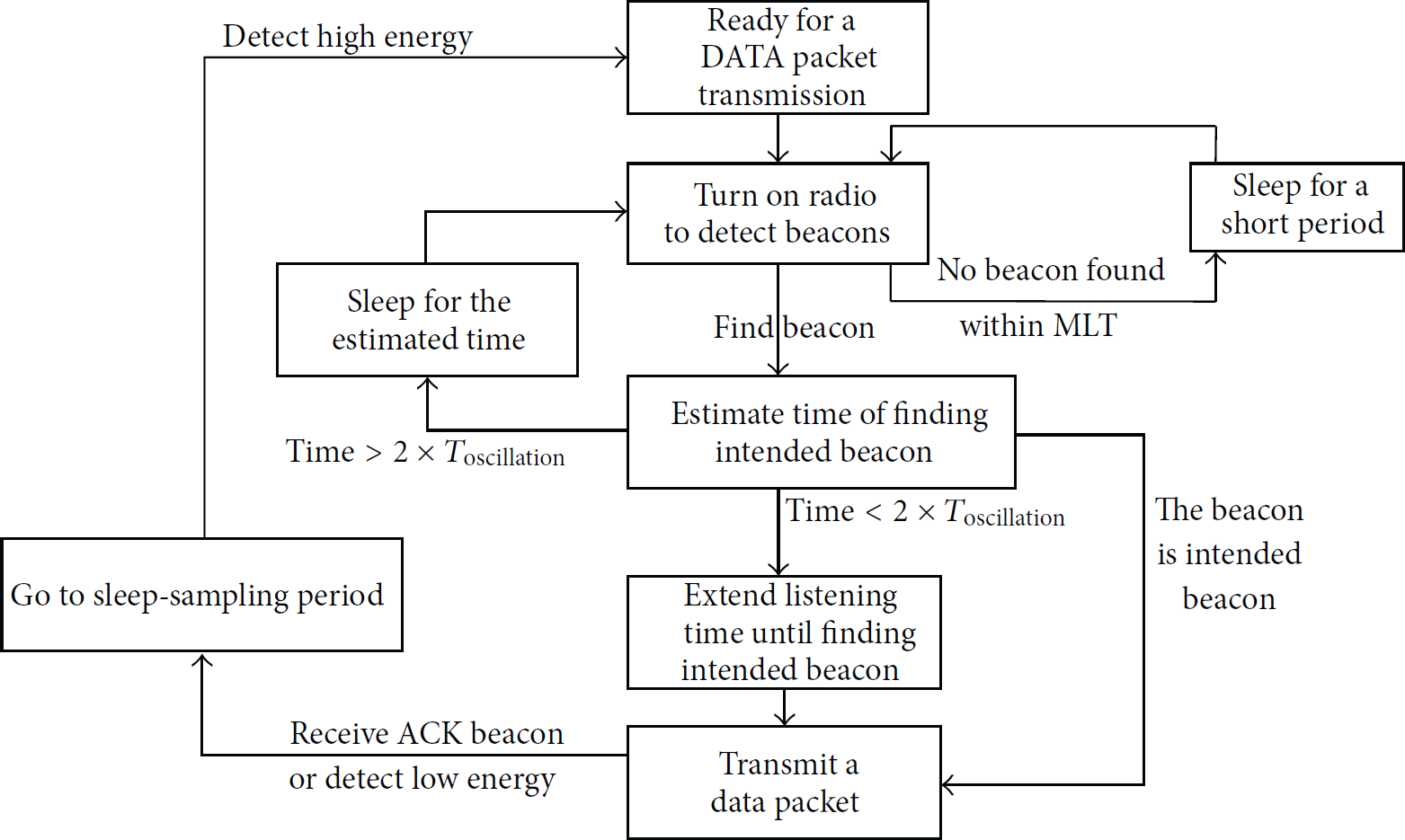
Working process of BSR node.
5. Test Results
5.1. Operation Modes and Current Consumption
A BSR node operates in three modes: sleep mode (SM), data sampling mode (DSM), and active mode (AM) (Figure 17). During sleep mode, μC works in power-save mode with an external low frequency crystal controlled 32 KHz clock to minimize power use while maintaining accurate timing. All other components, including RFIC, Regulator 2, and FPGA, are turned off. The current in sleep mode (

Time sequence versus current (SM: sleep mode; DSM: data sampling mode; AM: active mode; NSM: nominal sleep mode).
Since the data sampling and active mode currents are much higher than the charging current to the energy harvesting storage capacitor, the most difficult part of the design is achieving acceptable biosensor data rate. To quantity this constraint, we next look at the current consumption level of the major components. Figure 18 depicts the measurement setup. Measured current consumptions for different modes are recorded in Table 4.
Current measurement results.


Current measurement setup.
5.2. Maximum Data Sampling Rate Analysis
The maximum data sampling rate (MDSR), which is defined as the maximum data that can be sampled and successfully transmitted during active mode, is an indicator of system capability. The data sampling rate

MDSR versus time spent in Rx modes (accelerometer (ACC) sensor and electromyography (EMG) sensor).
5.3. Average Listening Time (ALT) for the GRI-MAC Layer Design
Although GRI-MAC layer design eliminates packet collisions and increases system reliability, the design incurs extra energy costs associated with listening to the intended beacon. Average listening time (ALT) for individual BSR nodes must be quantified, consequently identifying the corresponding maximum sampling rate. ALT is the average time that a BSR node listens to find its intended beacon. The BSR node process shows that the listening time for a BSR node has three possible conditions: detect intended beacon within MLT, detect intended beacon in extended listening time, and detect intended beacon in the next wake-up time. ALT can be calculated by the equation,

ALT versus number of BSR nodes.
6. Conclusions
6.1. Summary
Energy harvesting wireless sensor networks (EHWSNs) have gained popularity as they do not rely on external power source availability [5], have longer transceiver node lifetime, and offer operational safety in special environments (e.g., inside space suits). This paper, which discusses both physical layer and medium access control (MAC) layer design, demonstrates EHWSN design inside a space suit. The EHWSN in this case study considers a star topology network with multiple biosensor radio (BSR) nodes and one gateway radio (GR) node. A GR node acts as a central node to receive data packets sent by BSR nodes and organize the network. The gateway node is assumed to be power-unconstrained. All BSR nodes are powered by thermal energy harvesting system (TEHS) which provides very low output power (≈1 mW). An experiment is conducted to replicate real thermal energy flow in the proposed hardware to estimate output power during practical use. The measurement result (output power = 0.87 mW) is a key parameter to calculate the BSR node duty cycle. Based on this duty cycle analysis, a new GRI- (gateway radio initiated-) MAC layer is presented and analyzed.
6.2. Future Work
Due to the extremely low duty cycle (≤0.4%) and low Tx rate (10 kbit/s), MDSR in this system is only 1.5 Hz~4.5 Hz, which is less than some biosensor signal sampling rate requirements. Two aspects including TEHS and Tx rate must be improved in order to realize higher MDSR. Current TEHS with 0.87 mW overall output power is designed using only two parallel thermal electrical generators (TEGs) and more than two-thirds of harvested energy is wasted in ultralow voltage step-up converter (UVSC). In order to increase TEHS output power, a new structure with more TEGs must be designed and a new USVC must be found. Tx rate is limited primarily by the current demodulation method. As link budget studies suggest that significant link margin exists within the envisioned space suit application [29], new methods can be employed to achieve higher Tx rate. If we can increase the Tx rate from 10 kbit/s to 1 Mbit/s without significantly changing the current architecture, MDSR can reach as high as 300 Hz which is adequate for most biosensor signals. Obtained MDSR value currently is based primarily on analytical calculations and MAC simulation. In order to obtain more accurate estimates of MDSR under realistic scenarios, the proposed MAC layer design needs to be implemented and tested and will be one of the tasks for future work.
Footnotes
Conflict of Interests
The authors declare that there is no conflict of interests regarding the publication of this paper.
Acknowledgments
This research is based on work supported by Kansas NASA EPSCoR grant number NNX11AM05A. The authors would like to acknowledge the efforts of many individuals who contributed to that project, developing associated energy harvesting components, prototype circuits, and associated software that made testing of the proposed methods and MAC layer possible [![]() ].
].