
Abstract
This work presents a novel unmanned vehicle system, capable of detecting risks in disaster areas. The rescuer can operate an unmanned vehicle to reach the disaster area via remote control. An android-based application program is used to control the remote vehicle via wireless network. The vehicle system is capable of detecting a variety of gases by the sensors deployed on it. The gas sensors can detect methane, ethane, and carbon dioxide. After detecting the gases, the vehicle passes the collected information to the rescuer for deciding which equipment can be used in the disaster. The gas detection sensors can reduce the injury risks of rescuers before they go into the disaster area. The vehicle is also equipped with a video surveillance camera to monitor the scene and find injured persons. A robotic arm is mounted on the head of the vehicle to grip objects and gather samples. Our unmanned system can effectively reduce casualties by gathering information about the disaster beforehand.
1. Introduction
Recently, the development of high-tech industries not only brings a lot of convenience for humans, but also causes more disasters that humans cannot handle such as pollutions, nuclear disaster, and other man-made disasters. When disasters happen, it is possible that the lives of relief workers are sacrificed in the rescue operations to save the lives of trapped people. How to save trapped people is very important, but more importantly is how to protect the lives and safety of relief workers and perform the rescue operation efficiently and successfully [1–3]. Therefore, tools are developed to assist relief workers and to gather information of the disaster scene in advance. Information of the scene is useful for judging the degree of the disaster and deciding suitable equipment for dealing with the disaster. But the collection of such scene information by actual personnel is not recommended due to safety concerns.
Unmanned vehicles are suitable for collecting the scene information [1–12]. Two popular vehicles are used for the purpose of ground and aerial vehicles [3, 5]. The ground vehicle can carry several special sensors to detect carbon dioxide, propane, temperature, and others [3, 6]. Such vehicle can easily travel on flat ground, but it is not suitable for bumpy ground or puddles. Topographical constraints compel the ground vehicle to perform route planning in the disaster scene, but the aerial vehicle can easily approach the scene without such route planning. However, aerial vehicle is not suitable for locations with strong winds. It is also unable to carry gas sensors for detection since the vehicle cannot get close enough to the scene.
These two vehicles often carry cameras to transmit images of the scene back to the command center via wireless network [3, 6–9, 11]. They also can be operated by remote control [3, 4, 6, 8–11]. But such vehicle equipment is very expensive and is difficult to obtain due to financial constraints of the local government [1].
Hence, the development of a smaller and cheaper vehicle which carries special-purpose sensors to detect the disaster becomes very important. This paper presents an unmanned ground vehicle design which meets the above objectives. The vehicle assists relief workers to gather the needed information of the disaster scene in advance by carrying several sensors to detect different gases. It also carries a camera to transmit real-time image of the scene back to the command center as well as a robotic arm to grip objects and gather samples. The vehicle can be driven over bumpy ground by controlling its three-pair wheels separately with different torsion force. The vehicle with multifunctions is suitable for different rescue tasks and can be easily controlled by a tablet PC or a mobile phone with the android operation system. Our unmanned system can effectively reduce casualties by gathering information pertaining to the disaster in advance.
The implementation of our unmanned vehicle system includes system architecture and control flow described in Section 2. Section 3 introduces the detailed hardware (HW) and software (SW) implementations, respectively. The experimental results are presented in Section 4, and the conclusion is given in Section 5.
2. Unmanned Vehicle System Design
2.1. System Architecture Design
As Figure 1 shows, our vehicle system architecture consists of six parts including the graphic user control interface [3], the 802.11 wireless network (or Wi-Fi) transmission unit [1, 3, 6–8, 11], the main control unit, the motor and arm control unit, the sensor detection unit [3, 4], and the image transmission unit [1–12]. The system can detect different gases using sensors, grip the object by a robotic arm, and transmit the scene image via Wi-Fi wireless network. Six parts of the vehicle functions are described as follows.

Proposed unmanned vehicle system architecture.
2.1.1. Graphic User Control Interface
The graphic user control interface is utilized to control the directions of vehicle and robotic arm and display the vehicle speed, gas concentration, obstacle warning notice, and scene images. The interface is designed as a mobile application (or called APP) installed on the android operation system. Relief worker can install the program on a mobile phone or a tablet PC and use it to control the remote vehicle via Wi-Fi network.
2.1.2. Wireless Network Transmission Unit
The unit is the interface between the user control and the vehicle. All control commands from relief worker are transmitted to the vehicle via the Wi-Fi wireless network, and feedback information such as gas concentration value and images are also transmitted back to the user control interface.
2.1.3. Main Control Unit
The main control unit controls the entire embedded system located on the vehicle; it controls the gas and sonar sensors, the camera, and the wireless network unit. It also transmits control commands to the motor and arm control unit.
2.1.4. Motor and Arm Control Unit
The unit transmits pulse width modulation (PWM) signals with different duty cycles to the motor drive circuit. The PWM signals are transmitted to the DC motors of vehicle axles after signal amplification. They are used to control the speed and direction of vehicle.
2.1.5. Sensor Detection Unit
The unit consists of two gas sensors and one sonar sensor. The gas sensor detects the gas concentration and the sonar sensor detects the range between the vehicle and the barrier.
2.1.6. Image Transmission Unit
Scene images are captured by the camera equipped on the vehicle and transmitted back to the remote control panel. The camera is also utilized to adjust the direction of robotic arm by setting the camera to an appropriate position.
In order to drive on different road conditions, our design utilizes six-wheel drive off-road vehicle. It can overcome rugged terrain and carry more weight. The vehicle is equipped with several functional units for detecting and searching the scene. Before dispatching relief workers to the scene, the vehicle can be sent first and gather the disaster information in advance.
2.2. System Control Flow
Figure 2 presents the proposed system control flow. It shows signal communications between each subfunction. When the system starts, relief worker uses an android-based graphic control interface to operate the vehicle via 802.11 g wireless network. A main controller located on the vehicle controls all sensors, camera, and robotic arm. It also communicates with the remote graphic control interface and sends commands to control the vehicle via the motor control board. All commands from the operator and all signals from devices of the vehicle are packed in a specific format before communication.
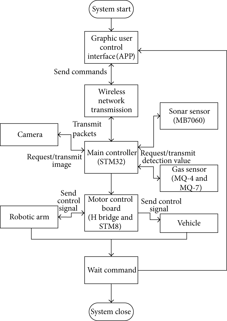
Proposed system control flow.
Retrieved signals from the gas sensors are translated to the corresponding value by the main controller, and then transmitted to the user control interface for judging the gas concentration. Signals from sonar sensor represents the distance between the vehicle and barriers. The distance detection function aims to avoid collisions of the vehicle during traveling. Images from the camera are packed by the main controller and transmitted to the remote user control interface.
Commands transmitted to the motor control board are separated into two parts: control speed or direction of vehicle and control direction or grip of robotic arm. These commands are transmitted from main control and translated to PWM signals after signal amplification.
3. System Hardware and Software Interfaces
3.1. Hardware Interface
In this system, several hardware designs are proposed including main control, motor and robotic arm control, and sonar and gas detection boards. These boards are all deployed in the vehicle to perform specific functions. Four major circuit boards of the vehicle are described as follows.
3.1.1. Main Control Board
Figure 3 presents a main control board that receives control commands from the remote software control program, transmits control signals to the designated hardware circuit boards, and receives feedback signals from the hardware circuit boards. ARM STM32 microcontroller performs the major communication interface between hardware circuit boards. All signals transmitted from one board to another board are transferred by the main control board. General purpose input/output (GPIO) ports in this board are used to connect other circuit boards.

Proposed main control board based on ARM STM32 microcontroller.
3.1.2. Motor and Robotic Arm Control Board
Figure 4 presents a motor and arm control board. The major core of the control board is an ARM STM8 microcontroller. It communicates with ARM STM32 which dominated the main control board via RS-232 interface. The control signals are also sent to the motor driving circuit and robotic arm driving circuit via the RS-232 interface.

Proposed motor and arm control board based on ARM STM8 microcontroller.
3.1.3. Motor Drive Board
Figure 5 presents our proposed motor drive board for controlling DC permanent magnet gear motors of the vehicle. It receives specific PWM signal from ARM STM8 microcontroller of the motor and arm control board. The PWM signal with a certain voltage drop can drive the axle and the signal with different duty cycles can change rotation speed of the axle. In our design, the wheels located on two sides of vehicle can be controlled separately by using different PWM signals.
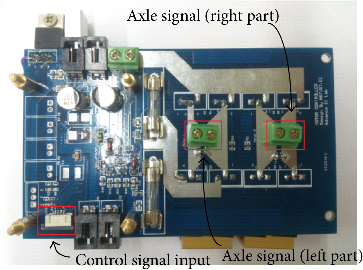
Proposed motor drive board.
3.1.4. Propane and Carbon Monoxide Detection Board
In order to detect harmful gases of the disaster site, two gas detection sensors are deployed in the vehicle to detect the concentration of gas as shown in Figure 6. MQ-4 sensor is utilized to detect the concentration of propane and MQ-7 is utilized to detect the concentration of carbon monoxide. The methods of concentration measurement in these two sensors are the same. When the detection operation starts, the Al2O3 ceramic tube in the sensor is heated and the concentration of detected gas causes SnO2 sensing layer output specific resistance value. The concentration of gas can be calculated by an equation related to resistance value.
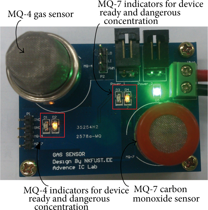
Proposed sonar and gas detection board.
3.2. Software Computing and Control
Hardware interfaces are designed to submit signals for controlling the vehicle, sensor, and robotic arm. Software programs set up in the tablet are also used to control the bending of the robotic arm, calculate the gas concentration, and transfer signals between the hardware and software interfaces via a graphic user interface (GUI) [3]. Three major parts of software application programs related to the vehicle systems are described as follows.
3.2.1. Concentration Calculation of Propane and Carbon Dioxide
STM32 microcontroller dominates the main controller as shown in Figure 2. If STM32 receives commands from relief worker to measure gas concentration, the STM32 sends signals to two gas sensors (MQ-4 Methane CNG gas sensor and MQ-7 carbon monoxide sensor). These two sensors generate different resistance values after performing measurement processes. The resistance values on these sensors cannot be measured directly. Hence, a resistor

3.2.2. Bending Control of Robotic Arm
The robotic arm deployed on the vehicle uses six servomotors to control its bending. Figure 7 shows the extended arm before starting to grip an object. Two servomotors numbered 1 and 2 are used to control the rotation and clamping of the claw to grip an object, and four servomotors numbered from 3 to 6 are used to control the bending of the arm. For example, in Figure 8, the bending of arm is performed by activating the other four servomotors in the sequence of numbers 6 to 3. When the object is griped, the arm is folded by activating the same four servomotors in the sequence of numbers 3 to 6. Control commands of the arm from the software program are packaged in specific formats and transmitted to the arm control board.
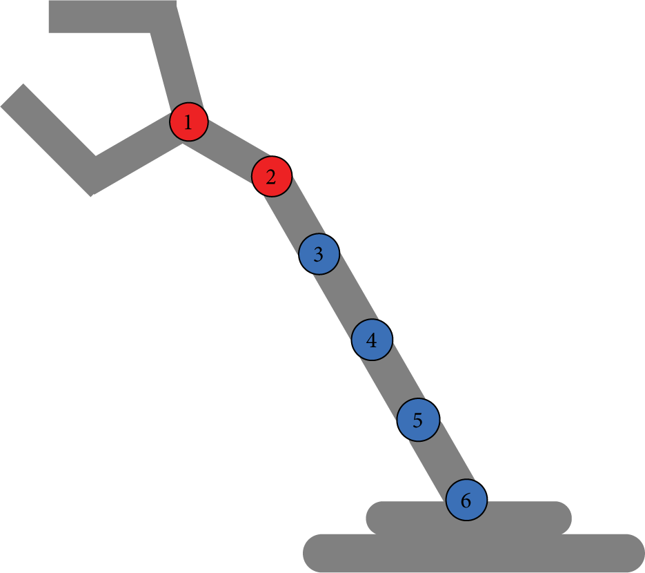
The robotic arm performs a straightened operation.

The robotic arm performs a winding operation.
3.2.3. Android-Based Control Interface
The vehicle is controlled by a remote android-based control program via Wi-Fi wireless network. The graphic user interface (GUI) of the control program is shown as in Figure 9. It consists of five parts including vehicle control, robotic arm control, sonar and sensor detection, and IP camera control functions. Commands from the control interface and feedback information from the vehicle are all packaged using the TCP/IP protocol. Specific packets are used to communicate between the vehicle and the tablet. Sockets of android and Microsoft windows operation systems play the role of communication interface between these two systems. When the vehicle system starts, the GUI in a tablet performs a connection with the vehicle via the Wi-Fi network. The GUI controls the direction and speed of the vehicle, and controls operations of the robotic arm. The GUI also receives sensor signals and scene images from the sensors and the camera separately.
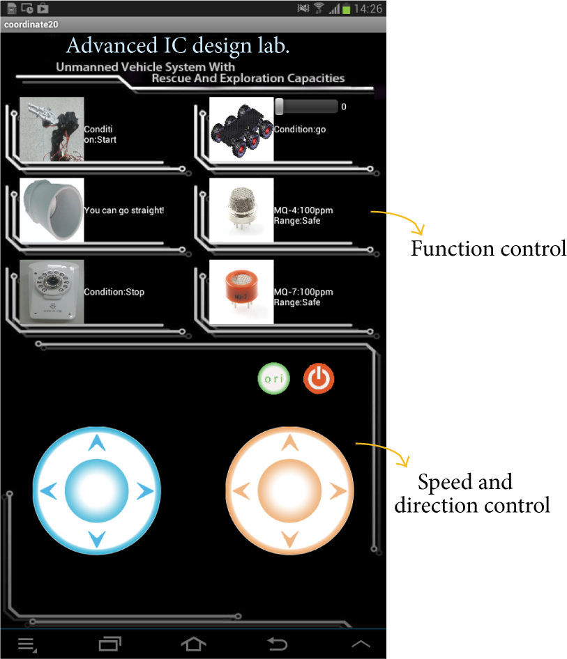
Proposed graphic user interface of system control program.
Two circular slide buttons colored with blue and orange are designed below the control interface in Figure 9. When the user selects the right upper button for controlling the movements of the vehicle, the blue button controls the speed of the vehicle and the orange one controls the direction. The paths that the vehicle takes to reach the disaster site may be filled with obstacles and potholes. Hence, it is very important to control the wheels of speed according to the road conditions. The user can move his finger within the boundary of the blue button to control the moving speed of the remote vehicle. The distance from the center of the circle is used to change the speed of the vehicle farther away from the center causing the vehicle to move with faster speed. When the user's finger moves away from the circle, the vehicle will stop its movements.
A similar way is used to control the robotic arm. When the user selects the left upper button patterned with a robotic arm, the blue button controls the arm's up and down motions, and the orange one controls the claw. The steering of the camera is also controlled by the orange button after the button patterned with a camera is selected.
The sonar is used to detect the distance between the barrier and the vehicle. When the barrier is too close to the head of the vehicle, the vehicle will slow down and finally stop. The warning message also pops up in the GUI to remind the operator of vehicle. Propane and carbon dioxide can be detected by using the MQ-4 and MQ-7 sensors separately. Concentrations of the two gases are revealed on the right side of the buttons patterned with MQ-4 and MQ-7 sensors. If the concentration is over a dangerous value, a warning message is displayed. The android-based GUI can be set up in a tablet or a mobile phone for easily transportation to the disaster site and can easy control the vehicle.
4. Experimental Results
4.1. Functional Tests of the Vehicle
The vehicle system is tested to verify its functions at different disaster sites. Several places are selected for performing the experiments. Major testing items are used to find disadvantages of the vehicle system and improve them such that the vehicles can be suitable for the disaster site. It is important to find whether the vehicle has the ability to overcome the challenges of different terrains. Several important tests are performed simultaneously including sonar and gas sensor detections, and the control of robotic arm via video images. The tests as mentioned above use the GUI of a software program installed in a remote tablet to submit control commands.
Table 1 shows the characteristic comparison of different unmanned vehicles for disaster detection [1]. The vehicle Seekur Jr. has the maximum payload which allows more subsystems or goods to be carried. The payload of our vehicle is not great as that of the more costly vehicles. But our vehicle has the minimal weight and six individual driven wheels which easily overcomes rough terrains. The last column of the table lists the capabilities of the vehicles. The optional subsystems that Seekur Jr. can deploy are the same as those of the P3-AT. If the vehicle carries more subsystems, the user needs to spend more money to buy them. The table also reveals that most of the unmanned vehicles are expensive and have limited capabilities in their original features. The vehicle Koala 2.5 has the lowest cost of about US$8.5 K on average and is capable of obstacle detection, networking, and GPS orientation. The advantages of our vehicle include low design cost, more capabilities, and easy control interface compared to other designs. The design cost of our prototype system is less than US$0.6 K, and the capabilities of our vehicle include obstacle detection, gas detection, object gripping, camera vision, and Wi-Fi network connection. Our vehicle has the unique capability of gas detection for measuring the concentration of propane and carbon monoxide. The control program of our vehicle can be easily installed on any android-based platforms such as a tablet PC or a mobile phone.
Characteristic comparison of different unmanned vehicle designs.

Table 2 shows the successful rate of barrier detection under different vehicle speed and relative distance. There are three vehicle speeds: low, medium, and high speed. The relative distance is the distance between the vehicle and the obstacle. For example, the vehicle speed is considered as low speed (30 km/hr), regardless of the relative distance, since the car can be successfully stopped in front of the obstacle. But when the vehicle speeds are medium (50 km/hr) and high speed (70 km/hr), with relative distances of 2.5 meter, the vehicle only has a 50% success rate to stop in front of the obstacle. According to the physics of movement, the vehicle is too heavy and its speed is too fast, which resulted in the vehicle being unable to brake within short distances. Hence, it is important to provide training to teach the operator to control the vehicle under certain speeds.
The successful rate of obstacle detection under different vehicle speed and relative distance.
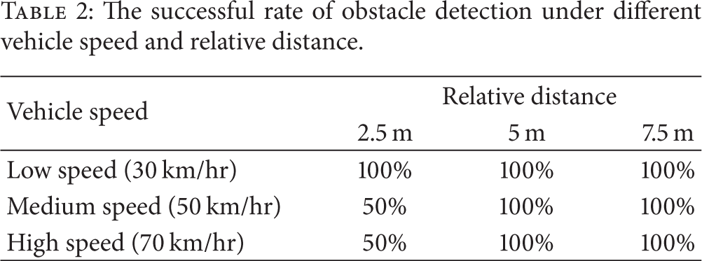
Figure 10 presents a scenario where the vehicle goes into the disaster site and picks up a specific object. The camera in the vehicle helps to search the object and transmits video images to the remote software control interface. The rescuer can find the object according to the images. The robotic arm is activated when the vehicle is close to the object. The arm operation is started by receiving the commands from the remote control interface. After picking up the object, the arm holds it in a stable posture and can move away from the disaster site. The whole vehicle system is presented in Figure 11. The vehicle carries one robotic arm, one sonar sensor, one camera, two gas sensors, and four control boards. The tablet is installed with a GUI-based control program, a network communication program, and an image processing program. The vehicle system with multisensor detections is suitable to be adapted to different disaster sites and decrease the damage.
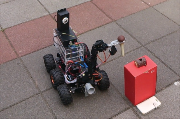
Proposed unmanned vehicle grips an object via the robotic arm.

Proposed unmanned vehicle system.
4.2. Experimental Results of Gas Concentration Measurement
As mentioned in Section 3.2.1, the voltage of internal resistance
The corresponding table of propane concentration and voltage of

Another experiment on the concentration measurement of carbon monoxide is also carried out by using the MQ-7 sensor. The voltage value
The corresponding table of carbon monoxide concentration and voltage of
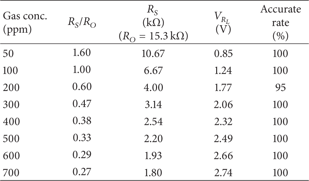
To evaluate the performance and accuracy of the gas detection board as shown in Figure 6, a closed plastic box is used to cover the vehicle which deploys the board and fixed amounts of gases are injected into the box. For example, in one experiment for measuring the propane concentration of 200 ppm, the propane is injected from a gas cylinder and a concentration measurement device is placed in the box for monitoring the gas concentration. Once the concentration reaches 200 ppm, the propane injection is stopped. Experiments with different concentration measurements are performed twenty times each and the average accuracy rate is evaluated as follows:

The gas detection board can detect the gas concentration quickly and provide the correct information to rescuers. These two sensors on the detection board are useful for detecting two common gases: propane and carbon monoxide, which are often present in fire accident sites. These two gases can quickly cause serious consequences to trapped people as well as rescuers. Hence, if the gases are detected before the rescuers go into the disaster site, the casualties will be reduced.
5. Conclusions
The proposed unmanned ground vehicle system is capable of detecting different gas concentrations and using robotic arm to grip the object. The system is a low-cost, high-efficiency system that can dispatch the vehicle into the disaster scene and collect the scene information such as gas concentrations and scene images for judging the degree of the disaster. Real-time information can be transmitted back to the remote operator via wireless network. The gathered information can be utilized to decide which equipment to carry by relief workers to reduce casualties and resolve the disaster effectively. Therefore, the development of a cheaper vehicle system with multifunction capabilities is useful for assisting relief workers in a disaster scenario.
Footnotes
Conflict of Interests
The authors declare that there is no conflict of interests regarding the publication of this paper.
Acknowledgment
The authors would like to thank the Ministry of Education of the Republic of China, Taiwan, for financially supporting this research under Contract no. C302-04.