
Abstract
Service robots have shown an impressive potential in providing assistance and guidance in various environments, such as supermarkets, shopping malls, homes, airports, and libraries. Due to the low cost and contactless way of communication, radiofrequency identification (RFID) technology provides a solution to overcome the difficulties (e.g., occlusions) that the traditional line-of-sight sensors (e.g., cameras and laser range finders) face. In this paper, we address the applications of using passive ultrahigh frequency (UHF) RFID as a sensing technology for mobile robots to track dynamic objects. More precisely, we combine a two-stage dynamic motion model with the dual particle filter to capture the dynamic motion of the object and to quickly recover from failures in tracking. The state estimation from the particle filter is used in combination with the VFH+ (Vector Field Histogram) to guide the robot towards the target. This is then integrated into a framework, which allows the robot to search for both static and dynamic tags, follow them, and maintain the distance between them. We finally tested our approach on a SCITOS G5 service robot through various experiments.
1. Introduction
For a mobile robot, the ability to detect and track an object is a key issue to efficiently interact with its environment. Extensive research regarding object tracking has been done based on vision- [1] or range-based sensors [2]. The goal of object tracking is to acquire the trajectories of an object by localizing it at each sensor update, which usually has to solve the object detection and object tracking issues individually or jointly. Vision-based tracking is challenging, since it has to deal with occlusions, motion uncertainties, and appearance changes of the environment. As compared to vision-based sensors, range-based sensors have longer reading range and are robust against illumination changes. Still, they have to face the difficulty of occlusions from the environment.
The usage of UHF RFID technology provides a way to overcome this difficulty, due to its automatic, contactless, and inexpensive way of identification. The UHF RFID tags absorb, modulate, and backscatter the electromagnetic waves emitted from the reader and thus are able to respond up to a limited range (e.g., 7 m to 10 m). In the scope of this paper, we focus on tracking dynamic objects with RFID tags using a mobile platform. As compared to the traditional vision-based or range-based sensors, passive UHF RFID features the following characteristics:
The RFID reader reports the IDs of the tags attached to objects directly, which does not require any additional algorithm for object detection. These IDs can be used as identities of the objects, which further simplify the recognition process involved in the traditional approaches. The radio signal can pass through the objects as well as obstacles and thus can deal with occlusions that challenge the field of vision-based or range-based approaches. Moreover, the feature of communication without line of sight makes the RFID technology independent of the illumination of the environment, which is a big problem for vision-based approaches. An RFID detection gives the coarse area about where the object should be. Although the RFID reader is not able to provide the position or the bearing of a tag directly, this information can be reasoned through a stream of RFID measurements in the history with a Bayesian filter.
The new generation of RFID readers is additionally able to report the respective received signal strength (RSS). However, modeling the characteristics of radio signals is challenging, due to many influencing factors on the propagation of signals like multipath effects, interferences, and occlusions. In this paper, we present an approach that uses radio signals from RFID tags to track dynamic objects. As shown in Figure 1, our robot is tracking a person carrying an RFID tag in a library environment. We use a combination of a two-stage dynamic motion model and a dual particle filter, also known as dual MCL (Monte Carlo localization), to deal with the motion uncertainty of moving objects and to recover from the tracking failures, respectively. Our approach requires a sensor model to approximate the positions of the objects, which actually does not need to be too precise. The fast tracking of dynamic objects is achieved at a cost of the overall mapping accuracy. Low rate estimation from the RFID device is used in a combination with the VFH+ (Vector Field Histogram), which serves as a local path planner for obstacle avoidance and navigation towards the target. VFH+ also has an integrated speed controller (both for the forward and angular velocity). Additional experiments in different scenarios were conducted to show the effectiveness of our approach.
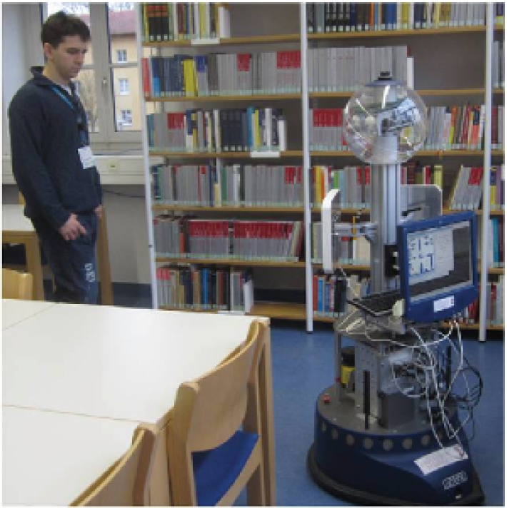
Our robot is tracking a person carrying an RFID tag in a library environment.
The work also represents an extended version of our previous publication at [3]. Particularly, in this paper we thoroughly analyze our approach in order to give a better understanding of its performance.
We organize the rest of this paper as follows. We review the related work in Section 2 and describe the Bayesian framework for tracking RFID tags in Section 3. Afterwards, we introduce the sensor model and the semiautonomous approach to learn the sensor model in Sections 4 and 5, respectively. Then, we present the combination of a two-stage motion model and the dual MCL for tracking RFID tags in Section 6. We explain the searching, navigating, and sensing framework in Section 7. Last, we demonstrate the experimental results in Section 8 and conclude this paper in Section 9.
2. Related Work
The process of navigating a mobile robot towards a tagged object is similar to the problems of source localization. In the field of source (e.g., gas) localization, the typical task that a mobile robot has to perform is to navigate towards an interested source or generate the concentration map of an environment. For an overview of the source localization approaches, we refer to [4]. In the context of the radio-based navigation, on the one hand, the signal strength of a tag highly depends on the relative pose between the tag and antenna. This provides a useful measure of the position or the bearing of a tag and thus can be used to navigate the mobile system towards a tagged object. On the other hand, besides the pose of the tag, many environmental factors (e.g., materials the tag is affixed to and interferences from the environment) also have significant impact on the signal strength. This makes the task of navigating a mobile robot using radio signals challenging.
According to the literature, the techniques of RFID-based navigation can be categorized into three classes: behavior-based approach, model-based approach, and sensor fusion-based approach.
2.1. Behavior-Based Approach
For the behavior-based approach, the robot gradually corrects its actions according to the information obtained from the sensor without modeling the internal representation. In the context of RF-based navigation, a simple and a fast way to navigate a robot towards RFID tags is presented in [5]. This approach uses the RSS difference between two RFID antennas and calculates the angular velocity according to that difference. The robot stops searching once there are obstacles in front of it. Sometimes the reactive controller fails in navigating towards the target due to the low signal strength provided by the two RFID antennas. In all cases when the reactive controller failed, our approach succeeded, since it always had the estimated pose of the object at its disposal, as shown in Section 8.5. Gueaieb and Miah [6] used the phase difference of RFID signals, which allows the robot to follow the virtual paths that link the tags' orthogonal projections to the ground. However, their approach has to rely on the phase difference provided by a customized RFID system and the configurations of tags are fixed (i.e., the tags have to be installed on the ceiling of an indoor environment). Kim et al. [7] developed an automated location sensing and docking system by utilizing a dual directional RFID antenna, which is able to estimate the direction of arrival (DOA) of the radio signal. However, the estimation of DOA is done with an active RFID system with loop antennas and currently it is not available in the market. Liu et al. [8] used RFID tags as reference landmarks to let the robot follow a complex path based on the signal strength and the odometry in unknown environments (e.g., a library or a hallway environment). Since this approach has to rely on a fingerprinting-based approach for position estimation, a large number of tags have to be installed in the environment in order to get a good navigation accuracy.
2.2. Model-Based Approach
In contrast to the behavior-based approach, the model-based approach usually uses well-calibrated models to localize the tags. The first work about how to localize passive RFID tags using a mobile system was presented in [9]. A model which characterizes the detection likelihood of a tag with reference to the antenna frame is used to determine the positions of the tags using a particle filter given several detection positions from a mobile robot. Vorst and Zell [10] pointed out that this sensor model can be learned semiautonomously during the normal navigation of the robot by placing several reference tags in the environment. Joho et al. [11] incorporated the signal strength into the sensor model to improve the mapping accuracy of RFID tags. In our previous work [12], we used a 3D sensor model and a pair of antennas to estimate the 3D positions of the RFID tags. There, we installed two antennas at different heights on the robot to solve the ambiguity problem of heights estimation introduced by antennas placed at the same height. But all of these approaches only deal with static RFID tags; in this paper we address the problem of tracking dynamic RFID tags using two RFID antennas, as described in Section 6.
2.3. Fusing RFID with Other Sensors
Germa et al. [13] combined RFID measurements with visual information to track people using a mobile robot in a crowded environment. In that case, the RFID system was used to determine the direction of the object and its readings have to be fused with a vision algorithm to get a better estimation of the position. They also designed a sensor-based controller to make the robot follow a tagged person. Deyle et al. [14] presented an approach that generated the RSS image of a tagged object for manipulation tasks of mobile robots. They constructed this image by rotating (i.e., panning and tilting) a mobile antenna and recorded the signal strength at the same time. The RSS image was then fused with the image from a camera and the point cloud from a 3D laser scanner to locate the tag in 3D. This approach was demonstrated on a mobile platform for finding, approaching, and grasping objects equipped with RFID tags. However, this paper shows that we can rely only on the RFID sensor for person tracking (and, additionally, a laser scanner for obstacle avoidance), as shown in Section 7 for more details.
3. Tracking RFID Tags
To estimate the tag position
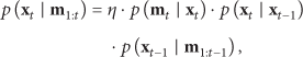

For the implementation, we use a particle filter (PF) to track the position of a tag. The PF consists of N samples at position hypotheses
(1) Prediction. Generate particles based on the motion model
(2) Correction. The weight
(3) Resampling. A set of new samples is drawn with probabilities proportional to the weights.
Similar to Liu and West [15], we perturb the particles after resampling. This strategy is also used by Joho et al. [11] and Vorst [16] for RFID-based mapping. Particularly, let


4. Sensor Model
The sensor model is essential for the tracking of RFID tags. The most relevant parameter of the sensor model is the displacement of the tag in the antenna frame. Formally, we want to know the likelihood of receiving a measurement


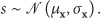
We further assume that the signal strength distribution is Gaussian, with a mean


RFID reader characteristics. (a) Detection probability. (b) Mean signal strength. (c) Combined sensor model, which describes the likelihood of a tag with
5. Semiautonomous Learning of the Sensor Model
In order to generate the sensor model, some researchers used supervised approaches to record the measurements by varying the relative pose of the antenna and the tag. For example, Hähnel et al. [9] rotated the robot in front of a tag affixed to a box. By repeatedly doing this at various distances, they obtained a grid-based representation of the sensor model. The disadvantage of the supervised approach is that the recording phase takes a lot of time if only one tag is involved in the experiment.
We utilized the semiautonomous approach proposed in [10] to learn the sensor model from empirical measurements. The idea behind this approach is to utilize the fact that the mobile robot can be localized by a rather accurate localization mechanism, for example, laser-based Monte Carlo algorithm, and thus it can explore the environment and meanwhile collect the RFID measurements.
To build up the sensor model, a list of reference tags, whose positions are known, must be installed in the environment beforehand. The sensor model, therefore, is learned by means of averaging the characteristics of tags across the entire database. Note that, in order to achieve a good position estimation in the tracking stage, the arrangement of the reference tags should be similar to the target scenario.
More precisely, the robot has to collect the measurements by traversing the environment either autonomously or manually in an exploration stage. During this stage, the RFID detections and the positions of the robot as well as the odometry data are stamped and recorded. Particularly, the position of the robot is estimated by a laser-based Monte Carlo localization algorithm. Based on the recorded measurements, an offline stage is performed to generate the sensor model following the steps described below.
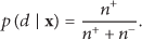
(i) Data Preprocessing. At each time step, the relative positions of the reference tags in the antenna coordinate frame are computed, given the global pose of the robot and the positions of the tags as well as the transformations between the antennas and robot. In this way, each tag produces a sample, which consists of the position
(ii) Model Generation. We use these raw samples to compute the conditional probability density function

(iii) Model Storage. For each grid cell, we precompute the likelihood of receiving a positive detection with all possible signal strength values according to (9) and store them as a look-up table. In this case, the memory required for storing the model is proportional to the band of the signal strength and the grid size used for discretization. The grid size has to be chosen carefully: a large grid size may not be able to describe the details of the probability density function, while a too small grid size may lead to the overfitting problem, since small number of samples is not enough to give a good estimation of the probability density function in a given grid.
6. Dynamic Motion Model and the Dual MCL
In order to let the robot react quickly to the movement of the objects, the tracking algorithm requires a robust and fast estimation. Particle filter-based trackers need to solve the problem of motion uncertainty (e.g., abrupt and fast motions of the objects). A poor motion model may place a small number of particles (or no particles at all) around the true pose of the tracked target, which leads to tracking failures. However, it is almost impossible to build up an accurate motion model due to the dynamics of the objects. To deal with this challenge, we utilized a two-stage dynamic model, which is similar to the ideas in [19, 20]. More precisely, we integrate two basic motion models, a slow motion model and fast motion model, both of which are modeled as a Gaussian with different standard deviations, namely,
Moreover, the pose estimation accuracy of the RFID tags highly depends on the influence from the environment [5]. The regular particle filter places a few or no particles around the true tag position and is not able to recover from this kidnapped problem. Lenser and Veloso [21] showed that this problem can be solved by sensor resetting, that is, adding new samples, which are generated according to the current measurement. Gutmann and Fox [22] showed a better way to determine the number of the particles by two smoothed estimations of the likelihood. But the generated new samples may cause an inconsistency to the current probability density function. In this paper, we solve this problem (i.e., kidnapped problem) by using the dual MCL [23], which draws particles from the observations and weighs them according to the current probability estimation. This approach has been developed specifically for extremely accurate sensor information, and the weighting makes it consistent with the recursive posterior estimation.
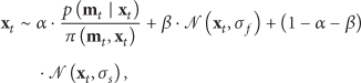
In particular, we determine the importance weights of new particles by reconstructing the belief using kernel density estimation (KDE) (see [23] for more information) based on the current estimation. In our application, it is straightforward to draw particles based on the current observation, since we have built up a precise sensor model for the measurements (see Section 4). Similar to [22], we generate these samples using a 2D grid with a resolution of 20 cm. In total, we draw α particles according to the dual MCL based on the current measurement, β particles with a fast motion parameter
7. Active Perception
By integrating the state estimator into a local path planner, we are able to track an object carrying an RFID tag and avoid obstacles at the same time. We choose VFH+ [24] as our local path planner. VFH+ was already implemented in the Orca-Robotics project (http://orca-robotics.sf.net/). It combines the following behaviors: obstacle avoidance, target tracking, and velocity control. We then integrate it into a framework, which allows the robot to search for a tag, track it, and stop in front of it.
We summarize the whole searching, tracking behavior as follows (also shown in Figure 3).

State machine representing the whole searching and tracking behavior.
(i) Exploration. The robot explores the environment along a predefined path to search for a specific RFID tag until the tag is found. To search for the tag, the robot is programmed to simply follow several waypoints in the environment.
(ii) Navigation. The robot navigates towards the target with an RFID tag using VFH+, if the distance between the target and the robot is smaller than a threshold (e.g., 0.5 m).
(iii) Active Sensing. The robot rotates for a certain angle (e.g., ±45°) to check if the signal strength is higher than a threshold (e.g., −47 dBm). It switches into the Navigation state, if the signal strength is smaller than the threshold.
(iv) Success. The robot approaches the tag successfully, once the signal strength is higher than the RSS threshold.
8. Experimental Results
8.1. Experimental Setup
We implemented our approach on a SCITOS G5 service robot provided by Metralabs (http://www.metralabs.com/), as shown in Figure 4. The robot is equipped with a laser range finder SICK S300 (

The experimental platform used in this paper and the main sensors equipped on the robot.
To learn the sensor model, we have placed 47 UHF RFID (Alien Technology Squiggle) tags in a hallway environment. These tags were placed at the same height as the antennas and their positions were measured beforehand. We manually controlled the robot to move along various trajectories with a maximum forward velocity of 0.3 m/s. The robot traveled approximately 2 km, and we recorded nine log files using the full reader power configuration (i.e., 30 dBm). We set the frequency of the reader to 2 Hz; that is, the RFID reader scans the surrounding tags twice per second.
8.2. Memory Storage and Time Consumption
The time used to generate the sensor model and the memory required to store the sensor model under different grid sizes are listed in Table 1. The experiments were conducted based on processing nine log files recorded at full power level using an Intel Core i5-2410M@2.3 GHz CPU, with 4 GB RAM. As seen in Table 1, storing a model with a smaller grid size requires more memory than a larger grid size. Moreover, computing the sensor model with a smaller grid size obviously takes more time than a larger grid size. Since the sensor model is generated in an offline fashion, the computational time is not an issue in our case.
Analysis of the time used for computing the sensor model and the memory required for storing the sensor model under different grid sizes.

8.3. Sensor Characteristics
The detection likelihood and the mean signal strength with a full reader power level are visualized in Figures 2(a) and 2(b), respectively. One can notice that the propagation of the radio wave is highly directional, since the detection mainly happens in the positive x-axis. The reader sometimes is able to detect the tag beyond 6 meters at the full reader power level. Detections in the negative x-axis, that is, behind the antenna, happen rarely. Moreover, the detection region does not follow a strict confined shape: there is a transitional region from high detection probability to low detection probability. Combining the signal strength model (mean and standard deviation of the signal strength) and the tag detection model (see Figure 2(a)), we are able to compute the combined sensor model, as shown in Figures 2(c) and 2(d), which visualizes the likelihood of detecting a tag with a given signal strength. As can be seen in Figures 2(c) and 2(d), a higher signal strength provides a strong belief about the position of the tag, while a lower signal strength introduces uncertainty about the position of the tag.
We also compared the sensor characteristics with respect to different reader power levels. The distributions of the signal strength over various power scales are visualized in Figure 5(a). As one can see in Figure 5(a), with a higher reader power level, the reader is able to provide a wider range of the signal strengths (see [−72 dBm : −38 dBm] for the high power level and [−68 dBm : −38 dBm] for the low power level), since the tag requires a minimum power to energize its circuitry, which leads to a change of the signal strength distribution in accordance with the changes of the reader power. The distributions of the signal strength at different distances are visualized in Figure 5(b). One can infer that the distribution of the signal strength can be fitted with a Gaussian very well. Moreover, the signal strength with a large distance is smaller than the one with a small distance. For example, the mean signal strength at 4 meters is about −62 dBm, as compared to −57 dBm at 2 meters.

(a) Histograms of the signal strength under different power levels. (b) Histograms of the signal strength at different distances. Note that the histograms visualized here are normalized.
8.4. Detection Characteristics of Tags Affixed to Different Materials
Up to now, all of the RFID sensor models are generated in a relatively ideal or controlled environment (i.e., the tags are affixed to walls without any interference of the material nearby). It is reasonable to apply this sensor model in controlled infrastructures. However, in practice, the mobile robot has to deal with the tags affixed to any kind of objects. For example, metal shelves, which are commonly used for many industrial environments due to the low price and mobility, may have a high influence on the readability and the signal strength of RFID tags. Many products, which contain water, also challenge the readability of the tags [5, 26]. To show the variance of the sensor models, we fixed the tags to two different objects, namely, a bottle of water and a metal box. The resulting tag detection model and the mean signal strength are shown in Figure 6. One can see that the deviation of these sensor models is quite significant. The reading ranges in both cases become smaller, while the signal strength is quite different: the average signal strength of the tag affixed to a water bottle gets lower due to the absorptions of the water, while the signal strength in the case of metal box becomes higher due to the reflections of the metal.

Detection likelihood and mean signal strength under the influence of different materials.
Unfortunately, the literature related to the mapping of UHF RFID tags paid very little attention to the problems of the model variances. Most of the experiments in the related work were conducted in controlled environments. This is one reason why the traditional particle filters have the problem of mapping failures under uncontrolled environments, which is addressed in the next chapter. Obviously, one could think of designing a sensor model for individual RFID tags, since each tag provides a unique identifier; however, the huge effort involved in this process prevents its usage in extensive applications.
8.5. Comparison with the Reactive Controller
A simple and a fast way to navigate a robot towards RFID tags is presented in [5]. This approach uses the RSS difference between two RFID antennas and calculates the angular velocity according to that difference. In this case, forward velocity is constant (it may also be controlled, e.g., proportional to RSS). This approach will be referred to as the reactive controller, which is compared to our approach. The Impinj RFID reader used for the experiments gives RSS values from −72 dBm to −38 dBm. If there are no detections, RSS is set to −70 dBm.
In the implementation of the reactive controller, the forward velocity is fixed to
The experiments were conducted for approaching static objects in our laboratory of a size of
8.6. Influence of Various Motion Parameters on the Particle Filter
Some preliminary experiments were conducted to observe the influence of different motion parameters on the tracking accuracy. We have set

Impact of parameter β on the tracking accuracy. (a) Ground truth and the estimated distance from the robot to the tag with different β. (b) Mean and standard deviation of the tracking error under different β.

Trajectories of the reactive approach and our approach.
Next, we performed experiments in a hallway environment to show the influence of parameter β on the tracking accuracy. In all the trials, a person carrying a tag was moving along the central line of the hallway with
8.7. Influence of Different Materials
As mentioned before, the environmental factors have high influence on the propagation of the radio signals. The readability of one tag is very poor, when water or metal is present, or when the tag is occluded. In the next series of experiments, we affixed the tag to different materials, that is, on a bottle full of water, on an iron object, inside and outside jeans, and outside and inside a sweater, as a name tag. In all cases, the tag was placed at the same height as the antenna.
For the cases when the tag was attached to the jeans, the robot had to follow the person from behind. This is motivated by the fact that more and more clothing stores will attach permanent tags to the clothes in the future. Again we conducted experiments in the same way as Section 8.6. We show the mean and standard deviation of the tracking accuracy in Figure 10. The trajectories of the robot during the tracking are shown in Figure 11. We noticed that the robot lost the person one or two times during the tracking of the tag attached to a bottle of water and inside jeans. We also observed that the robot was not able to follow a tag affixed to a metal object, which can be seen from the high tracking error (0.7 m) due to many circles that the robot made during the tracking. On the other hand, water has less influence on the tracking accuracy than metal, as can be seen in Figure 10. The reason for this is that metal and water have high influence on the propagation of the radio signal, which is shown in Figure 6 and also explained in Section 8.4.
8.8. Impact of Different Antenna and Tag Configurations
In the experiments presented in this section, we evaluated the influence of different antenna configurations and different heights of the tag during the object tracking. Different angles between the antennas (at the tag height of 0.8 m) were

Mean and standard deviation of the tracking error under the influence of different antenna setups and tag heights. (a) Tracking accuracy under the influence of different antenna setups. (b) Tracking accuracy under the influence of different tag heights.

Mean and standard deviation of the tracking error under different materials the tag is attached to.

Trajectories of the robot under the influence of different materials the tag is affixed to.
9. Conclusions
In this paper, we addressed the problem of tracking dynamic objects with a mobile robot using long range passive UHF RFID sensors. Particularly, we used a two-stage dynamic model and the dual MCL to capture the dynamics of moving objects and to quickly recover from tracking failures. With a laser scanner and an RFID sensor, the robot is able to track dynamic objects and avoid obstacles at the same time. Extensive experiments were performed with a SCITOS G5 to test the effectiveness of our approach.
There are several directions into which this work can be extended. First, the RFID reader only provides a coarse measurement of the position of the tag. Therefore, the obvious extension of this paper is the fusion with the metric measurements obtained from other sensors equipped on the robot, such as cameras or laser range finders, to improve the mapping accuracy. In this case, the object detection or recognition process can be further facilitated by taking advantage of both techniques.
Second, our current strategy chooses the shortest path to the goal, while the robot moves towards the target during the tracking. Therefore, an extension of this paper is to use heuristic control algorithms in order to quickly move towards the object and meanwhile obtain the maximum information gain (i.e., best reading rate of the tag attached to the object).
Footnotes
Conflict of Interests
The authors declare that there is no conflict of interests regarding the publication of this paper.