
Abstract
With the development of networks, Vehicular Ad-hoc Networks (VANETs) which act as the emerging application enhance the potential power of networks on the traffic safety and the entertainment. However, the high mobility and the dynamic nature of VANETs lead to the unreliable link which causes unreachable transmission and degrades the performance of the routing protocol in terms of the quality of experience (QoE). To provide a reliable routing for the data transmission, a self-adaptive and link-aware beaconless forwarding (SLBF) protocol is proposed. Based on the receiver based forwarding (RBF) scheme, SLBF designs a self-adaptive forwarding zone which is used to make the candidate nodes accurate. Furthermore, it proposes a comprehensive algorithm to calculate the waiting time by taking the greedy strategy, link quality, and the traffic load into account. With the NS-2 simulator, the performance of SLBF is demonstrated. The results show that the SLBF makes a great improvement in the delivery ratio, the end-to-end delay, and the average hops.
1. Introduction
With the existence of the Dedicated Short Range Communication (DSRC), Vehicular Ad-hoc Networks (VANETs) [1], which derive from the Mobile Ad-hoc Networks (MANETs), enhance applications for Internet service [2]. VANETs consist of three parts [3]: Road Side Unit (RSU), On Board Unit (OBU), and DSRC. The wireless communication in VANETs can be classified into two strategies: vehicle-to-vehicle (V2V) and vehicle-to-infrastructure (V2I). Recently, the applications in VANETs attract the users’ attention [4], which support Intelligent Transportation System (ITS) along with safety and nonsafety applications. It can be used in several scenarios [5, 6], and the typical example is the traffic accident scene. Once two moving vehicles make a collision, the emergency data or video transmission triggered by the nearby RSUs or vehicles permeates to the vehicles around and farther places via multihop routing, which can give the police and the ambulance workers more detailed information about the accident to make the first response and rescue operation quickly. The typical safety decision [7], such as to proceed, to wait, or to change another road, depends on the data or video transmission severely. Moreover, the delivery of entertainment information over VANETs helps the passengers consume time or even enjoy the trip. All those applications call for the trustful routing protocol. For example, the reliable transmission of the information can better show the situation of the accidents for police, ambulance workers, and fire-fighters so that the proper operations can be carried out properly. Furthermore, the transmission of the entertainment data also needs the reliable routing. All these pave the way to reliable information delivery over VANETs. All in all, many applications depend on the trustful transportation of the data, which require the routing with high reliability.
The quality of experience (QoE) is an important metric to measure the performance of video services and network operations [8]. In order to improve QoE, the needed data should be delivered to all users reliably. Sometimes, users need the video content to be presented or played when it is still in downloading [9]. However, the nonuniform distribution of nodes, the high mobility, and dynamic nature of VANETs pose great challenges [10, 11] in reliable data transmission. Therefore, the reliable transmission requires efficient routing protocol [12] to lower the packet loss and the delay to meet the high requirement of QoE.
According to our investigation, data forwarding scheme in VANETs can be classified into three categories [13]: traditional route based forwarding, sender based forwarding (SBF), and receiver based forwarding (RBF, also called the beaconless forwarding or the volunteer forwarding). The traditional route based forwarding schemes, like Ad hoc On-Demand Distance Vector Routing (AODV) [14] and Dynamic Source Routing (DSR) [15], stem from MANETs, which are not suitable for high mobility scenario in VANET [7] although VANET is a special kind of MANETs. In SBF scheme, the sender selects the next forwarders according to routing state tables which need the HELLO or beacons to be maintained and updated periodically; so the overhead in SBF is always higher. On the contrary, in RBF, the next forwarder is chosen according to the contention of the receiving node, in which the overhead is reduced because it does not need to maintain and update routing tables [12, 16].
In this paper, considering both the feature of VANETs and the challenge of data transmission, a novel protocol, namely, self-adaptive and link-aware beaconless forwarding (SLBF), is proposed, which uses the receiver based forwarding scheme. It includes two important issues: the definition of forwarding zone and calculation algorithm of waiting time. We make the following main contributions:
Compared with other RBFs, a self-adaptive forwarding zone is proposed, in which we define the forwarding zone from two parts: the direction and angle size. We call it a self-adaptive forwarding zone because the angle size of the zone of each forwarder can be adjusted based on the traffic density. Moreover, the direction of the forwarding zone is along the road which the vehicle is moving on, and the location of the destination has function to the direction. In contention scheme, the waiting time represents the priorities of the nodes. So we design a reliable algorithm aiming to ensure the quality of links. The waiting time is the key in the contention scheme, in which the greedy strategy, the link quality, and the traffic load are considered. In the link quality part, the duration time and the packet error rate are both taken into consideration. The duration time is defined as the maximum time a vehicle stays in the communication range of its last hop, and the conception of packet error rate comes from the bite error rate which is used in the video transmission mode.
In the rest of the paper, Section 2 surveys the existing receiver based protocols. Our assumption and the basic transmission scheme of SLBF are introduced in Section 3. The definition of the forwarding zone and the contention scheme are depicted in Section 4 and Section 5, respectively. Section 6 shows the simulation results. At last, we give the conclusion and the future work.
2. Related Work
The routing protocols in VANETs can be divided into two categories: the topology based routing and geographic routing protocol. As shown in Figure 1 [17], the receiver based (beaconless) routing belongs to the nonbeacon part of the non-DTN. In this section, we present the existing receiver based protocols and analyze them simply.

Classification of routing protocol in VANETs.
In the basic receiver based scheme, the node which is selected as the forwarding node broadcasts the received packet; then, the receiving nodes contend for the forwarding right according to the waiting time; at last, the node which wins the forwarding right is identified as the new forwarder. In the following, several classical RBF schemes are introduced in detail.
Juneho Moon proposed the virtual sink algorithm (VS) in [18], which calculates geographic points (virtual sink) at regular intervals as landmarks in the connecting line from the source to destination. Virtual regions are circle-shaped regions centered at each virtual point with a constant radius R. Each node that receives a packet in a virtual region transmits it to the next virtual region and ends the transmission until the packet reaches the destination. It uses the implicit ACK instead of the ACK scheme; however, all nodes in the virtual region cause the collisions and multipoint relay.
The fast triggering [19] is a video triggering solution which uses RBF scheme as well as greedy strategy. Once receiving the packet, the node which its waiting time expires first forwards the packet, and the other nodes which overhear the forwarding step discard the packets. The fast triggering uses periodical HELLO message to estimate the transmission range which affects the waiting time. The use of greedy strategy aims to shorten the delay, but the transmission of the periodic hello message increases the overhead.
By using RBF, trajectory based solution is proposed in SiFT (simple forwarding over trajectory) [20]. Compared with the fast triggering, the SiFT does not use the hello message. It defines the waiting time as the ratio about two distances, which is unreasonable as the ratio may be unchanged along with the variation of the distance.
The vehicle-to-vehicle live video streaming architecture (V3) [21] is a geographic based routing protocol with using receiver based scheme. It defines a data forwarding zone (DFZone) in which the nodes receiving the packet forward the packet immediately. It also uses the store-and-forward scheme which leads to the unacceptable delay.
Heissenbüttel et al. proposed a new algorithm called beaconless routing (BLR) [22] which follows a unique approach. In BLR, the selection of the next forwarder is totally distributed, in which the current forwarder just broadcasts the data packet and the closest neighbor to the destination rebroadcasts the packet because its timer expires in the first place. That is, the author only considers the distance to the destination in calculating the waiting time.
In [23], Video Reactive Tracking-Based Unicast Protocol (VIRTUS) is introduced. It is a geographic RBF solution designed to fulfill the task of video streaming over vehicular networks. The VIRTUS is a RBF scheme, which gives a great adaptability for the high moving nodes in VANETs. Also, it proposes innovative forwarding zone, reservation time, and a multiple forwarders prevention method to alleviate the drawbacks of RBF schemes. The forwarding zone in VIRTUS is a sector of its communication circle, in which the forwarding zone has a constant value and is directed towards the location of the destination. In this case, there may be no selectable node in the defined zone if the last hop is not in the same street with the destination node. It only considers the length of the duration time of link, and the character of the nonuniform distribution of nodes is not taken into account.
For the SLBF proposed in this paper, we modulate the angle of the forwarding zone considering the traffic density. The protocol uses the RBF scheme, defines an accurate forwarding zone, and evaluates a more comprehensive waiting time to realize a faithful packet delivery in VANETs. Moreover, we use the packet delivery ratio, average hops, and the end-to-end delay which have been analyzed in [24, 25] as the metrics to measure the performance of SLBF in simulation.
3. Assumption and Transmission Scheme
In this section, the assumption of network is introduced first. And then the basic forwarding scheme and the retransmission of SLBF are shown in detail.
3.1. Assumption
Considering a straight highway over which a network of vehicular resides, we make the following definitions and assumptions in this work.
3.1.1. ID
We assume that every vehicle has a unique ID number in the network, and each vehicle can get the location of every vehicle according to its ID number.
3.1.2. Distance
Every vehicle is equipped with GPS, and each one stores the local digital map. The location information of the vehicle is described as (longitude, latitude) which is obtained by the GPS device. Then, distance between nodes a and b in the network is defined by

3.1.3. Communication Range
We set the communication range of every node as a constant value which is equal to the wireless communication range (
3.1.4. Speed
The speed of every vehicle is constant in a small interval.
3.2. Basic Transmission Scheme of SLBF
The basic transmission scheme is the key part in SLBF. After the assumption, it shows the procedures to transmit the packets, in which the intermediate nodes and the source node are treated as the forwarder. Then, we introduce the basic transmission scheme of SLBF as the following steps:
First of all, the forwarder judges whether its distance to the destination is smaller than the communication range R. If so, the forwarder sends packet and ends the packet delivery. Otherwise, the forwarder embeds the information needed into the packets, broadcasts the packet, and sets a time Then, the receiving node judges whether it is in the forwarding zone of last hop based on the information of last hop in packet head. If it is not in the forwarding zone, it discards the packet. If the receiving node is in the forwarding zone, it calculates its waiting time and contends for the forwarding right according to the contention scheme. The node which wins the forwarding right is selected as the new forwarder and then returns back to Step (1). The other competitive nodes which overhear the transmission of the same packets cancel the timer and discard the packets. When the forwarder in Step (1) does not receive the broadcast packet within
In Step (1), the needed information includes four parts: the location information, the forwarding zone of the node which forwards the packet, the ID number of the destination, and the forwarding time point.
The node which receives the packet and in the forwarding zone of last hop (forwarding node) calculates its waiting time and then competes for the forwarding right based on the contention scheme.
We select the node which its waiting time expires first and does not overhear any transmission of the same packet as the winner of the contention. The winner is selected to act as a new forwarder. And the other competitive nodes in forwarding zone cancel their timer and delete the packet received.
3.3. Retransmission Scheme in SLBF
In the SLBF scheme, not only is the basic transmission needed, but also the retransmission scheme is necessary when the transmission failed. Also, we use last forwarder as the new forwarder when it needs to retransmit the packet.
In Step (1) of the basic transmission,
When it runs the retransmission, the location information of the node which forwards the packet and the forwarding time point in the packet will be updated. What is more, the forwarding zone of the retransmission is changed as the topology keeps changing. According to the definition of forwarding zone, the direction changes when the change of the moving direction of forwarder or the change of the location of the destination happens while the angle size is unchanged based on the calculation of the angle size.
We can see from the scheme mentioned above that the two key points in SLBF are the definition of forwarding zone and contention scheme, which are shown in the following sections in detail.
4. Forwarding Zone
As an important part of the SLBF, we first introduce the definition of the forwarding zone. In this part, we propose a self-adaptive forwarding zone from two aspects: the direction and the angle size, in which the forwarding zone is a fan-shaped area of a circle with radius R. As we know, the communication range of the node in the network is R. Therefore, it is reasonable that the reachable transmission area is a circle with radius R.
4.1. Direction
In [23], the direction of the forwarding zone is towards the destination, which is not suitable for the real road scenario because it may miss the most suitable potential forwarder to transmit the packet when the destination node is not in the same road with the current forwarder. In this case, it weakens the performance.
In SLBF, the direction of the forwarding zone is along the road, and the zone almost includes all the suitable nodes in the communication range according to the moving direction of forwarding node and the location of destination node. Here, the rectangular coordinate system is established with the forwarding node as the origin of coordinates and the moving direction of forwarding node as the x-axis. The angle between the x-axis and the line which connects the forwarding node and the destination determines the direction of the forwarding zone. When the absolute value of the angle is smaller than right angle, the direction of the forwarding zone is as the same as the moving direction of the forwarder; otherwise, it is in the opposite direction.
From the direction of the forwarding zone described above, we can see that the direction of forwarding zone is determined by the location of the forwarder and destination. Therefore, the direction of forwarding zone in retransmission scheme may change when the change of the moving direction of forwarder or the change of the location of the destination happens.
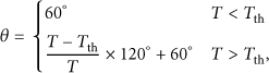
4.2. Angle Size
After defining the direction of the forwarding zone, we then introduce the self-adaptive angle of the fan-shaped area. We set the x-axis (or its opposite line) of forwarding node as the bisection of angle of forwarding zone. At first, we set the minimum angle of every forwarding node as
We can conclude that the calculation of the angle size involves the value of T. However, the retransmission scheme does not change the value of T according to its definition. Therefore, the angle size of forwarding zone in retransmission scheme is the same as its first try.
4.3. Illustration
As is shown in Figure 2, the red vehicle F is the current forwarding node; the green vehicle D is the destination node.

Direction of forwarding zone.
Eventually, we can see that the green part in Figure 2 is an example of the forwarding zone according to the definition described above.
5. Contention Scheme
The forwarding node broadcasts the packet, and then the nodes in the communication range R receive the packet. At first, the receiving node judges whether it is in the forwarding zone of last hop according to

Defining a suitable forwarding zone is the basic guarantee for SLBF. After judging whether they are in the forwarding zone, the receiving nodes in the zone become the candidate forwarders. Then, the candidate forwarders contend for the forwarding right. In the basic transmission part, we show that the contention scheme is the second key issue in this scheme. Moreover, in the contention scheme, the priority of the nodes is determined by the waiting time. Therefore, the waiting time algorithm is the key for the contention of the new forwarder. In the following, we introduce the waiting time calculation algorithm in detail, in which we take the greedy strategy, the link quality, and the traffic load into account.
5.1. Greedy Strategy
To improve the performance of the SLBF, we improve the quality of service (QoS) by lowering the delay and the average hop. For this reason, we choose the node which is in the communication range and the nearest to the destination as soon as possible as the most suitable new forwarder, which uses the idea of greedy strategy. Therefore, we consider the greedy strategy as one of the factors when calculating the waiting time. We adopt the normalization method used in VIRTUS [23] and can get the factor of greedy strategy from

For every receiving node, the distance from last hop to the destination (
5.2. Link Quality
The link quality which is very important for the routing protocols affects not only the transmission quality of packets but also the successful transmission of ACK. Therefore, to select the next forwarder efficiently, we take the link quality into account when calculating the waiting time.
As is known, the communication between two nodes happens when the two nodes meet the two conditions: the distance between the two nodes is not greater than the maximum communication range R and the link between two nodes is stable. Therefore, we consider the link quality from two parts: the duration time (
5.2.1. Duration Time
We define the duration time (

5.2.2. Packet Error Rate
The concept of packet error rate is introduced based on the bit error rate. In video streaming transmission, a whole packet is often treated as a transmission unit; so we use the influence of signal to interference plus noise ratio (
We adopt the video transmission mode to solve the received power. Initially, the received power of the signal


Therefore, the packet we need to forward may contain several bits (L); finally, the

Eventually, the factor of link quality (
5.3. Traffic Load
With focusing on the traffic of forwarder, we take the traffic load into account. The queuing delay of packet, an important factor for the performance of routing, is selected as the traffic load as the reason that the longer packet queuing leads to longer end-to-end delay. Then, we define the traffic load as

5.4. Waiting Time
Finally, considering the impact factors mentioned above, the waiting time can be obtained from

Above all, we present the SLBF in detail and then simulation results will be shown to verify the performance of SLBF.
6. Performance Evaluation
We use the NS-2 [26] to measure the performance of the proposed SLBF, as it is costly to be verified in real vehicular scenario. In this section, the simulation setup and the results are introduced.
6.1. Simulation Setup
To verify the performance of SLBF in VANETs, we use the NS-2, a popular network simulator in academia. This simulation environment we use is intelligent driver model (IDM) [27] which is a time-continuous car-following model for the simulation of freeway and urban traffic and is generated by the vehicular mobility generator VanetMobiSim that is a relatively realistic vehicular scenario for NS-2. Moreover, all the nodes in IDM are moving nodes and there are no stationary node and no Road Side Unit in our simulation. Also, it takes advantage of the two-ray ground propagation model and the IEEE 802.11 MAC with the fault data rate (
The SLBF is operating in a

Simulation scenario.
6.2. Simulation Results
Three key QoS metrics, which are also significant for QoE, are used to measure the performance of the proposed SLBF. The metrics are the packet delivery ratio, end-to-end delay, and the average hops. As we know, the packet delivery ratio and end-to-end delay are important elements to measure the performance of routing protocol while the average hops are relative to link quality severely.
We compare the proposed protocol with GPSR [30] and BLR [22]. BLR is the typical RBF protocol and we realize the simple forwarding scheme in simulation. GPSR is the classical geographic protocol; we choose GPSR since we use the greedy strategy in our scheme. Figures 4 and 5 are the packet delivery ratio and the end-to-end delay, respectively, and Figure 6 is average hops in first simulation scenario. Figure 7 is the delivery ratio; Figures 8 and 9 are the end-to-end delay and average hops in second simulation scenario, respectively. In the simulation figures, the parameters factors geo, link, and tload are α, β, and γ in (13), in which only one of the three is

Delivery ratio versus number of nodes.
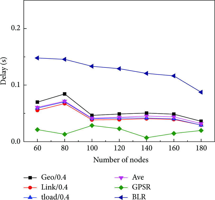
Delay versus number of nodes.

Hops versus number of nodes.
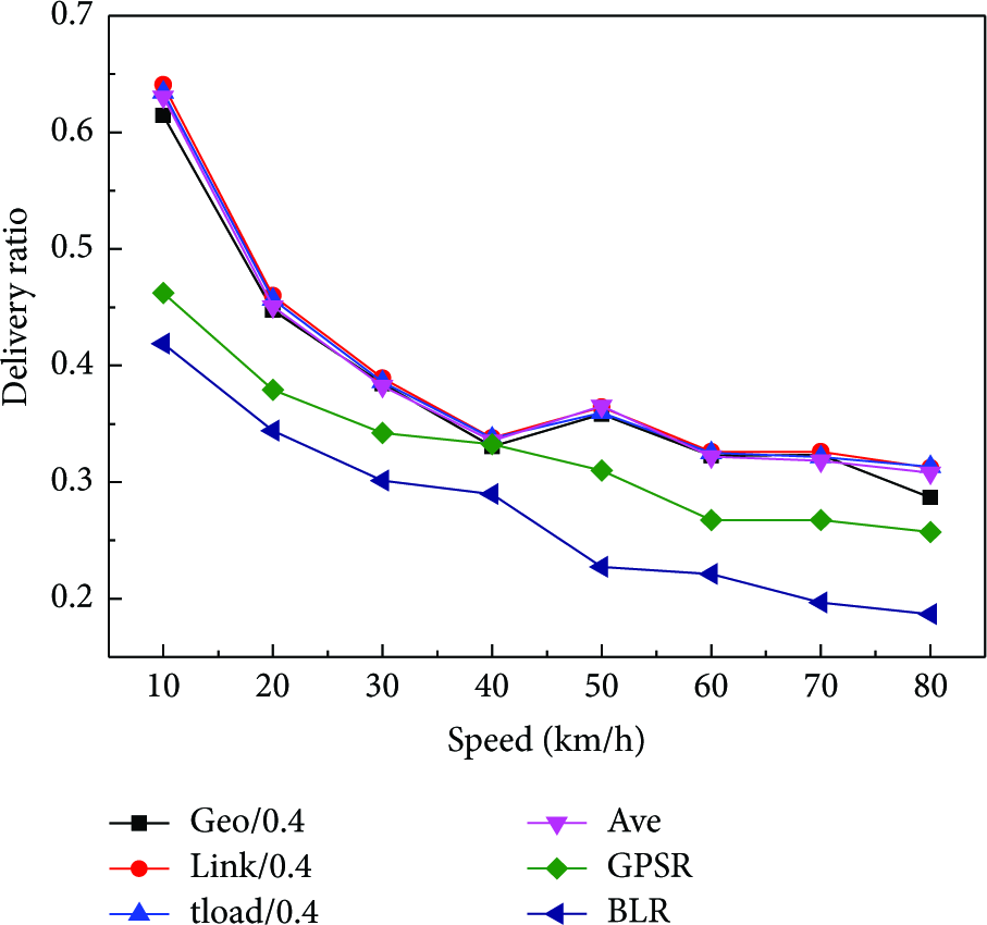
Delivery ratio versus speed.

Delay versus speed.

Hops versus speed.
From Figure 4, we can easily find that the packet delivery ratio of the SLBF is higher than GPSR and BLR, and the delivery ratio raises with the increase of the node number. The SLBF performs well as we consider the greedy strategy, the link quality, and the traffic load in calculating waiting time, which also uses the retransmission scheme when the forwarding of the packet fails. Also, the GPSR only uses the greedy strategy in normal case. While compared with the BLR, the SLBF uses the more reasonable forwarding zone with self-adaptive angle. The reason that the delivery ratio raises with the increasing of node number is that the increasing number of nodes improves the number of selectable nodes which can forward the packet. We can see from Figure 4 that the packet delivery ratio of REBP achieves up to 42.8% and 65.6% improvement compared to GPSR and BLR, respectively.
In Figure 5, the delay of the protocols is shown. We can see that the delay of the SLBF is greater than GPSR and is smaller than BLR. In SLBF, every forwarder has a timer of waiting time which is used to select the new forwarder, and the retransmission scheme in SLBF improves the delivery ratio at the cost of the longer delay. Meanwhile, the next hop in GPSR is the farthest node in the communication range; so the delay is relatively lower than the SLBF. The SLBF and BLR are all based on the RBF scheme; the reason why the delay of SLBF is smaller is that a self-adaptive forwarding zone is designed to make the candidate forwarder accurate. Moreover, we design a comprehensive algorithm for the calculation of waiting time.
Figure 6 shows the average hops of different protocols; the hops of the SLBF are greater than GPSR and lower than BLR. In GPSR, the greedy strategy is used in ordinary case, in which the current node forwards the packet to the node which is the farthest in communication range according to the routing table without other elements. The SLBF considers the greedy strategy, the link quality, and traffic load all to calculate the waiting time to determine the forwarding node. Also in SLBF, we can see that the hops are smaller than the other three when the geo (α) is
Figure 7 shows clearly that the packet delivery ratio of all the protocols decreases with the increasing speed, and SLBF keeps a relatively small superiority compared to the other two. As we all know, the higher the node moves, the more frequently the topology changes, which influences the delivery ratio significantly. In GPSR, only the greedy strategy is taken into account without any parameters about the element of node speed. The SLBF is a little better than BLR as it cares about the link quality which is relative to the moving speed.
From Figure 8, we can see the delay of the three protocols clearly. As in Figure 5, the delay of the SLBF is higher than GPSR and is smaller than BLR. Meanwhile, there is a relatively small increase in BLR and SLBF with the raising of the vehicular speed, as the increasing speed leads to the changing topology which affects the routing quality seriously. Because it considers the element of link quality, the changed trend of delay in SLBF is relatively small.
Figure 9 shows that the hops of SLBF are greater than GPSR and are smaller than BLR, and the hops increase with the raise of the speed. As we all know, the increasing speed leads to the high dynamic topology, which affects the selection of the new forwarder significantly. Although the link quality is considered in SLBF, the effect of intermittent link cannot be eliminated totally. Also in the GPSR and BLR, the hops go up with the added speed.
7. Conclusion and Future Work
Data transmission over VANETs enhances the application in traffic safety and entertainment significantly. However, the feature of VANETs, highly moving node, uneven node density, and dynamic topology, poses great challenges in reliable routing for data delivery. Therefore, we focus on the RBF scheme and propose the SLBF, in which we define a self-adaptive forwarding zone and design a comprehensive algorithm to calculate the waiting time with considering the greedy strategy, link quality, and the traffic load. And the simulation results show that the SLBF makes a great improvement, such that the packet delivery ratio of SLBF achieves up to 42.8% and 65.6% improvement compared to GPSR and BLR, respectively, in first scenario; also the end-to-end delay and average hops are smaller than BLR. All in all, the SLBF is an effective solution in data transmission in VANETs. The future work will be enhanced to the multipath routing based on the RBF scheme.
Footnotes
Conflict of Interests
The authors declare that there is no conflict of interests regarding the publication of this paper.
Acknowledgments
This work was supported by the National Natural Science Foundation of China under Grants no. 61271176 and no. 61401334, the Fundamental Research Funds for the Central Universities (BDY021403, JB140113), and the 111 Project (B08038).