
Abstract
An indoor surveillance system is proposed and carried out in this paper. The surveillance system consists of a home server, omnirobots, and static monitoring nodes. The omnirobots and static monitoring nodes form a surveillance sensor network which comprises several star-like wireless sensor networks. The static monitoring nodes sleep periodically and can be woken up by the pyroelectric infrared sensor. If an abnormal event happens, the static monitoring node will capture images and produce alert messages. An adaptive energy-efficient transmission method is proposed to prolong and balance the lifetime of each static monitoring node. The static monitoring nodes can adjust their transmission power according to the distance to the omnirobots. Meanwhile, the omnirobots can also adjust their positions to extend the lifetime of the surveillance sensor network. Experimental results demonstrate that the transmission power of the static monitoring nodes is minimized sufficiently. A 160 × 120 image can be transmitted within 2.1 s in the surveillance sensor network. The energy consumption of transmitting images without transmission security mechanism reduces by 21%. And it saves 11.7% of energy that an image is transmitted with the lowest transmission power. The surveillance sensor network can be conscious of the node loss and self-recovers timely.
1. Introduction
With the continuous development of the technology, home automation attracts more and more attentions. A safe and comfortable living environment is provided for people. In pace with the improvement of the human living standards, the demands for surveillance systems are constantly increasing. Remote surveillance is a critical function of home automation [1]. Traditional systems usually use the static surveillance devices mounted above the walls and roofs with cable connection [2, 3]. The costs of these systems are too high that an ordinary family cannot afford. In addition, these systems are too complicated to install and maintain.
Along with the advancements of the wireless sensor network (WSN) technology, numerous WSN-based surveillance systems were designed and manufactured in the past few years. The most noteworthy contribution of the WSN-based surveillance systems is that the system cost is reduced significantly. The simple and low-cost sensor nodes are applied into the home automation [4, 5]. The nodes which are equipped with various sensors can be easily installed. The monitoring nodes equipped with pyroelectric infrared (PIR) sensor form a multihop WSN [6, 7]. Once the monitoring nodes detect intruders breaking in, an alarm message will be sent to the house owners. However, these systems lack flexibility that only the static monitoring nodes are used.
To improve the poor flexibility of the surveillance systems, mobile robots are incorporated into the systems. In [8], a robotic pan-tilt-zoom camera was added into the surveillance system for capturing the images of intruders. More and more surveillance systems with the assistance of mobile robots are developed as the progress of robot technology, that is, wheeled robots [9], jumping robots [10, 11], and modular self-reconfigurable robots [12]. In [9–11], the mobile robots and the sensor nodes formed a single WSN. The network roles of these mobile robots were set as the gateway or mobile nodes. Other than that, the modular self-reconfigurable robot proposed in [12] established an extra WSN-based network for controlling the robot. Meanwhile, the static monitoring nodes form another multihop network. The modular self-reconfigurable robot not only gave assistance to monitor the home, but also provided a function of communication link repair.
The simple alarm function of these surveillance systems cannot satisfy the growing demands of the consumers. More and more devices were integrated into the monitoring nodes to enhance the function of the surveillance system. For example, microdigital cameras were integrated into the design of the wireless sensor nodes for obtaining media information in [13–15]. The camera sensor nodes can capture comprehensive information of the abnormal events. Owing to this, more energy is consumed by the on-board devices of the monitoring nodes. Moreover, the energy is also greatly consumed by the communication transceivers [16]. The monitoring nodes are commonly powered by the rechargeable batteries with limited power. Therefore, the lifetime extending of the monitoring nodes becomes a difficult problem to be settled.
Plenty of researches have been studied for reducing the energy consumption of the sensor nodes [17, 18]. The conventional method of energy conservation applied in the WSN is that the nodes sleep/wake up periodically [19]. Based on this, a node self-scheduling method based on the remaining energy was proposed in [20]. The method was to decide which node was required to switch to the sleep state. In [21], the authors introduced an energy-efficient wake-up scheduling for reducing the energy consumption. However, the real-time monitoring is the most basic function of the surveillance systems. Only a cyclical sleep/wake-up protocol is not appropriate for the surveillance system. The works in [22] presented an in-network data processing scheme which dynamically adjusted the voltage supply and the clock frequency of the on-board sensors. The energy consumption of computation is minimized through changing the operating modes of the devices. The data aggregation techniques were utilized to reduce the amount of data to solve the energy problems of the sensor nodes [23].
Yan et al. [24] proposed a strategy which minimizes the energy consumption from both the node level and the network level. An algorithm was designed to estimate the lowest transmission power before sending the data. In [25], the authors proposed a real-time power-aware routing protocol. Every route in the network was set up with adaptive transmission power. The energy consumption of the data transmission was reduced through adjusting the transmission power. A lazy schedule of packet transmissions that varied the packet transmission time judiciously was proposed for reducing the energy consumption [26]. Li et al. [27] proposed an approach which was comprised of packets combining and a modified lazy packet scheme. The energy consumption was reduced ulteriorly. Zhang et al. [28] proposed a concentric ring deployment scheme based on the battery current effect. But the deployment of the monitoring nodes in the surveillance system is unchangeable that all nodes are mounted above the doors and windows. The authors in [29] proposed a method which used the mobile nodes as relays, and multiple mobile robots were used as sink nodes in the network [30]. Both methods can increase the network lifetime significantly. To sum up, the problem of energy consumption can be settled through reducing the data size, decreasing the transmission power, and further combining the WSN and the mobile robots.
The goal of this paper is to extend the lifetime of the surveillance sensor network through prolonging and balancing the lifetime of each monitoring node. An adaptive energy-efficient transmission method is proposed to achieve this goal. The adaptive energy-efficient transmission method includes adaptive control of transmission power and the position estimation of the sink node. The surveillance sensor network consists of the omnirobots and monitoring nodes. The monitoring nodes send the data with the lowest transmission power. And the omnirobots can prolong the lifetime of the surveillance system through altering their positions. In addition, the network architecture, the hardware design, and the operating mode of monitoring nodes are optimized with consideration of energy consumption.
The rest of this paper is organized as follows. Section 2 introduces the overall architecture of the proposed indoor surveillance system. The energy consumption of the sensor node in conventional WSN is described in Section 3. Section 4 gives the optimized architecture of the surveillance sensor network. The design of event-driven monitoring nodes, the adaptive control of transmission power, and the image transmission are given in Section 5. The design and the position estimation method of the omnirobots are shown in Section 6. The experimental results on the adaptive energy-efficient transmission method, the image transmission, and the network recovery are provided in Section 7. Concluding remarks are given in Section 8.
2. System Overview
The conceptual architecture of the indoor surveillance system is illustrated in Figure 1. This system includes two levels of networks, that is, the internet network and the surveillance sensor network. The omnirobots communicate with the home server through the Wi-Fi. The owners can control the omnirobots to navigate in the house and monitor the house visually. The surveillance sensor network formed by the omnirobots and the monitoring nodes is used to detect intruders. The omnirobot plays an interface role between the monitoring nodes and the home server. The monitoring nodes are mounted above the windows and doorframes. The PIR sensor equipped by the monitoring nodes is utilized to detect the abnormal situation within its coverage. When the PIR sensor detects an intruder breaking into the house, it will trigger the monitoring nodes to capture images and send alarm messages to the omnirobot. The house owners will get the alarm message and the images of the intruders from the home server.

The architecture of the proposed surveillance system.
3. Energy Consumption of Sensor Nodes
Based on the first order radio model [31, 32], the energy consumed for transmitting and receiving k bits between two sensor nodes in WSNs is respectively expressed as follows:


WSNs have three distinct topologies, that is, star-like, tree-like, and mesh topologies. In a star-like network, all sensor nodes transmit data to the sink node directly. The energy consumption of each sensor node is calculated by:

If the topology of the WSN is a tree or mesh, the data would be transmitted through multihops. The total energy consumption that k bits data are sent to the sink node through M hops is given as:

Equations (3) and (4) present that the energy consumption is proportional to the distance and data size when the network depth is fixed. The longer the distance between the two sensor nodes is, the more the energy is consumed. Moreover, it also shows that the energy consumption increases with network depth increasing in (4). Therefore, network depth, data size, transmission power, and the communication distance should be taken into consideration when the surveillance network is designed.
4. Network Architecture of Surveillance System
Based on the above discussion about the energy consumption of the sensor nodes, the network architecture of the surveillance system is presented in Figure 2. The surveillance system includes a Wi-Fi based network and a surveillance sensor network. The Wi-Fi based network is a high-level network which comprises a home server and several omnirobots. The surveillance sensor network is a WSN-based network which is in charge of monitoring the house. The surveillance sensor network formed by the omnirobots and monitoring nodes contains plenty of star-like WSNs. Each star-like network is in charge of a region. The surveillance sensor networks formed in neighboring regions work in a different channel to prevent the interaction. The energy consumption of the monitoring nodes caused by multihop transmission is resolved by forming the star-like topology. The omnirobots are configured as the gateway of the two networks and the sink node of the surveillance sensor network.
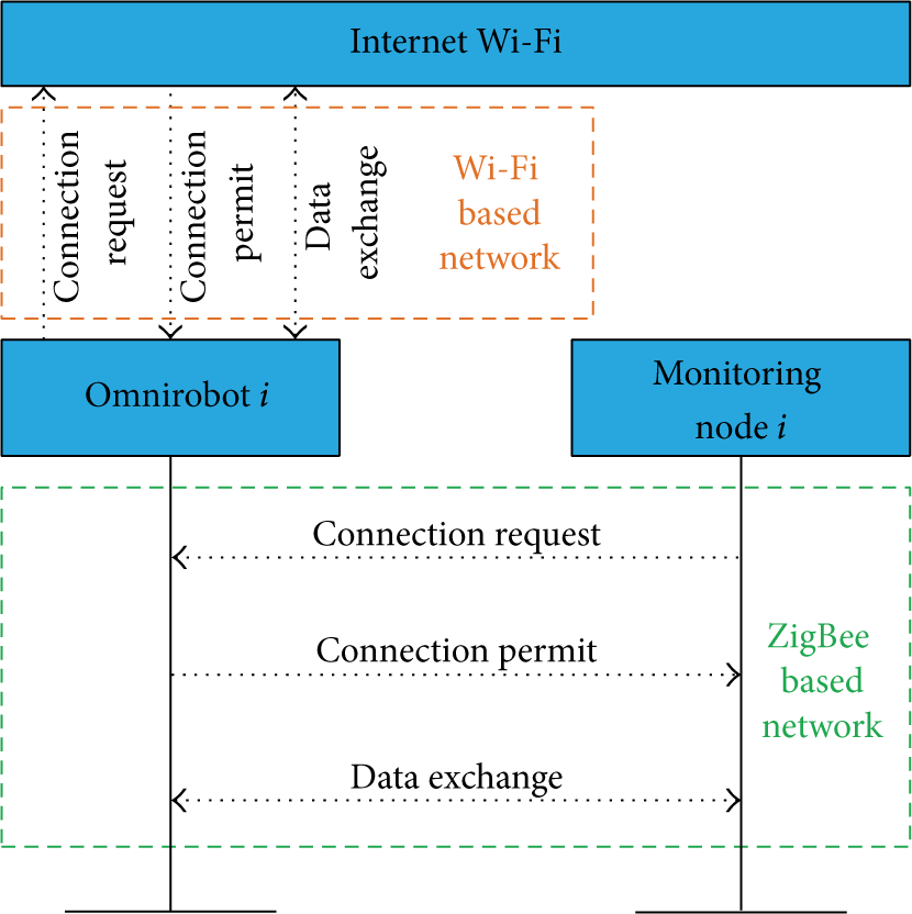
The network registration and data exchange procedures of the proposed surveillance communication system.
5. Event-Driven Monitoring Nodes
5.1. Monitoring Node Design
The hardware scheme of the monitoring nodes is shown in Figure 3. Each monitoring node is equipped with a ZigBee compliant module, a digital camera, and a PIR sensor. The ZigBee compliant module has a 32-bit RISC core and a 2.4 GHz transceiver. The over-the-air transmission rate of the transceiver is up to 250 Kb/s. The working current of the processor is approximately 37 mA. When the processor is in sleep mode, the working current is only 2.6 μA. The dimension of the image captured by the digital camera can be configured as
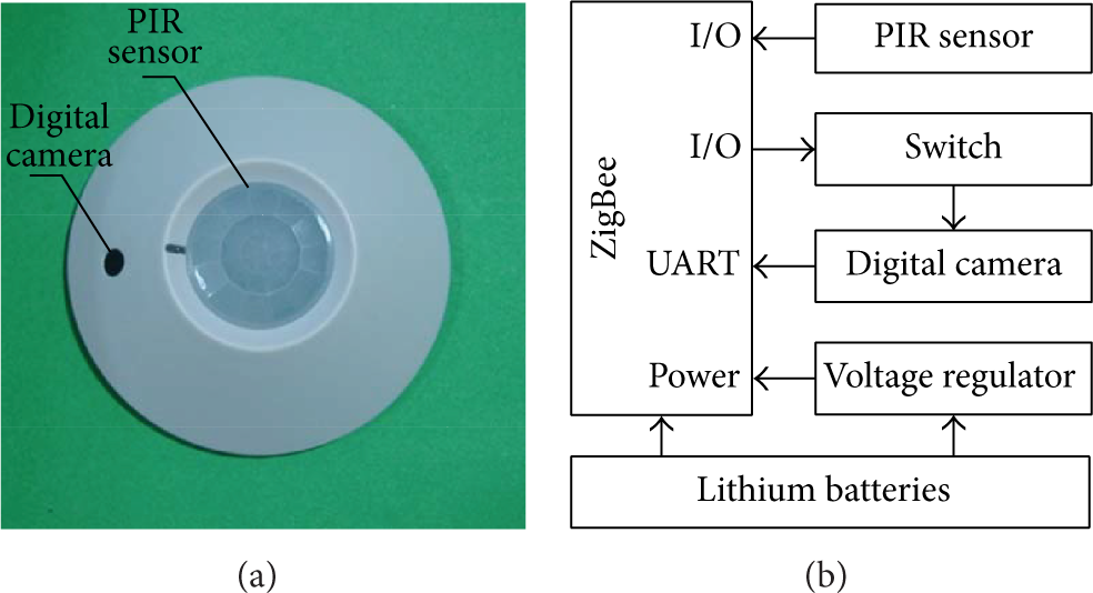
The prototype and hardware block diagram of the monitoring nodes.
5.2. Image Capture
The monitoring nodes are mounted above the windows and doors. The detecting area of the PIR sensor and the visual range of the digital camera are shown in Figure 4. The detecting angle α of the PIR sensor is 110°. The visual angle β of the digital camera is 120° that can cover the detecting area of the PIR sensor. As shown in Figure 4(a), the monitoring node is installed at the height of H. The axis of the PIR sensor is perpendicular to the ground. The length of the detecting area is calculated by (5). If the monitoring node is installed with a deflection angle of θ that is shown in Figure 4(b), the length of the detect area is expressed as (6). It can monitor more space out of the house. And the face of the intruders can also be captured:


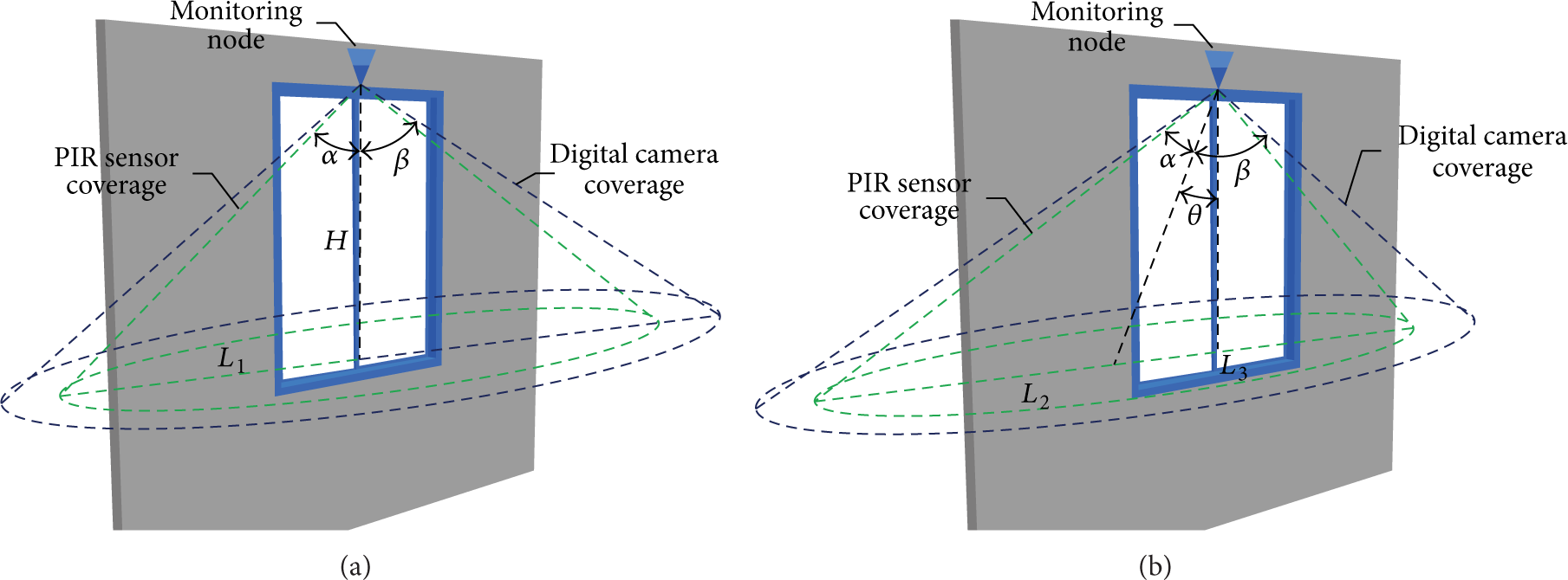
(a) The monitoring nodes installed on the window frame with the angle
As shown in Figure 4(a), the length of the detecting area is 6.3 m when the monitoring nodes are installed at a height of 2.2 m. The average walking velocity of an adult is about 3.5 m/s. So, it takes about 2.5 s when an adult walks through the detecting area. The average data size of a 320 × 240 image is about 14 KB. The processor of the ZigBee compliant module takes 1.23 s to read the data from the FIFO buffer of the digital camera. The digital camera can only capture two
5.3. Image Transmission
The digital camera equipped by the monitoring nodes captures six images continuously when an intruder passes through the detecting area. Therefore, the major data transmitted in the surveillance sensor network are image data. The data aggregation method present in [23] is not suitable for the applied ZigBee compliant module which has low computation power. The data frames of the surveillance sensor network are shown in Figure 5. A


The data packets format in the surveillance sensor network.
The acknowledgement mechanism is provided to ensure that the previous packet is received in the surveillance sensor network. However, this mechanism consumes extra energy for receiving a response frame. The extra energy consumption is calculated by:
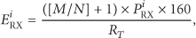
It can be observed that the energy consumption of the monitoring nodes increases with the number of packets increasing. To decrease the energy consumption, the transmission security mechanism is disabled. The wireless transmission of the ZigBee compliant module also consumes much power, notably image transmission. The transmission power of the transceiver can be adjusted in the range of −30 dBm to 0 dBm. If the transceiver applies the appropriate transmission power, the energy consumption will be ulteriorly reduced.
5.4. Adaptive Control of Transmission Power
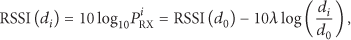
Based on the long distance path loss model [33, 34], the relation between the transmission power
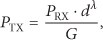
The minimum transmission power

If


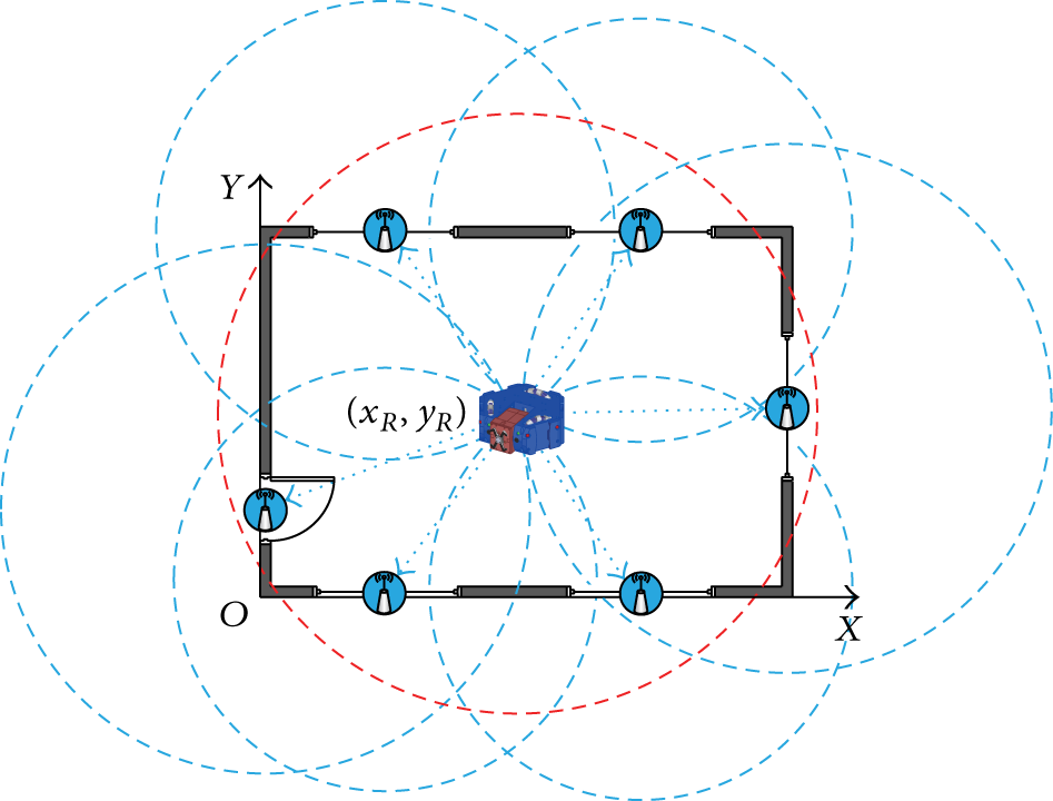
The transmission power of the transceiver can be configured as 0 dBm, −6 dBm, −12 dBm, −18 dBm, −24 dBm, and −30 dBm. The estimated transmission power will be configured as one of the six levels. As shown in Figure 6, the impacts of transmission power and distance on LQI were tested in the lab. The LQI does not decrease monotonously with the transmission power decreasing. The method proposed in [24] only uses
The impacts of the transmission power and distance on the LQI.

The work flow of the transmission power adaptive method.
6. Multiple Omnirobot Nodes
6.1. Omnirobot Design
The omnirobots are configured as the interface of the two networks and the sink node of the surveillance sensor network. The CAD structure of the omnirobots is shown in Figure 8(a). The size of the omnirobots is 142 mm × 144 mm × 48 mm. The pitch arm is driven by a digital servo. The prototype of the omnirobot is shown in Figure 8(b). Owing to the omnidirectional wheels, the omnirobot can perform flexible movements. Figure 8(c) shows the control hardware scheme of the omnirobots. The control board includes a ZigBee compliant processor and a Wi-Fi module. The omnirobots are powered by rechargeable batteries. When the omnirobots run out of power, they will automatically return to the wireless charging station. The processor exchanges data with the digital cameras and the Wi-Fi module through its UART ports. The Wi-Fi module provides 54 Mb/s transmission rate. The encoder and the inertial sensor can provide the information for the omnirobot to locate itself.

The CAD model, prototype, and hardware block diagram of the omnirobots.
6.2. Position Estimation of Omnirobots
The proposed adaptive transmission power approach can reduce the energy consumption of the monitoring nodes. The distance between the omnirobot and each node determines the transmission power of the nodes. If the position of the omnirobot is random, the results of the adaptive transmission power approach are different. The great difference of the transmission power of each node will result in imbalance of the lifetime of each monitoring node. Therefore, a position estimation method is proposed to find a position which can balance the transmission power of each monitoring node and the maximum lifetime of the surveillance sensor network.
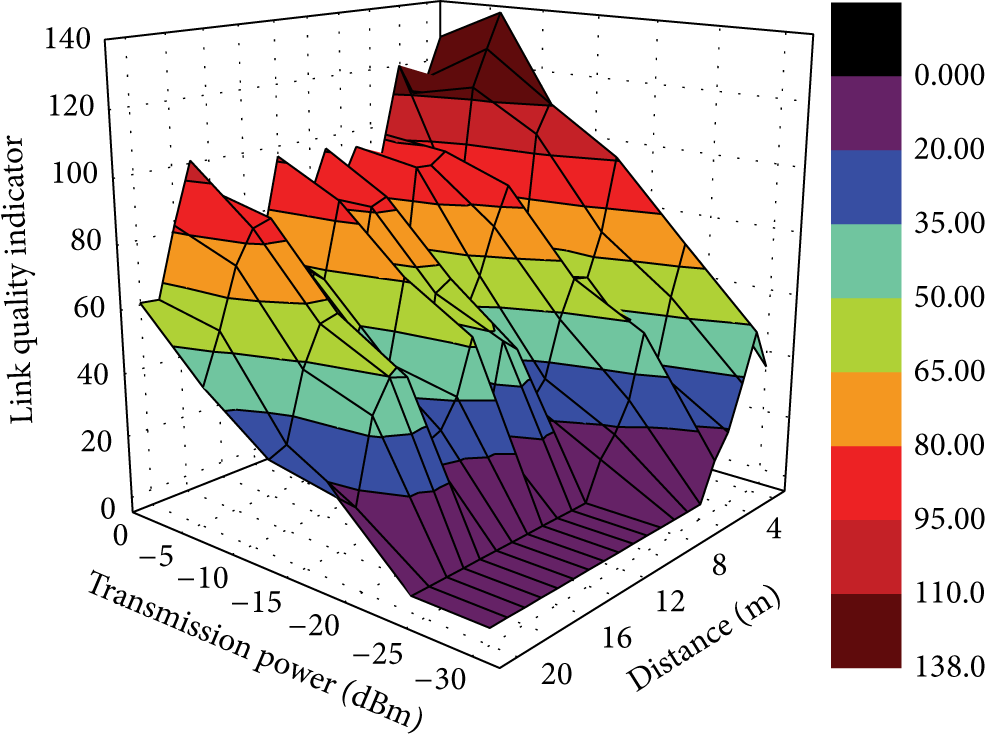
Figure 9 presents that the omnirobot and several monitoring nodes are in charge of monitoring a region. The monitoring nodes are all mounted above the doors and windows. And the omnirobot can be at any position within the region. The lifetime of the sensor node is commonly defined as the ratio of the remained energy to the transmission power [35, 36]. In this paper, the lifetime of the ith monitoring node is defined as (14). The remained energy of the battery is proportional to the battery voltage. The lifetime of each node is rewritten as (15). The lifetime of the surveillance sensor network is defined as the time to the first monitoring node that runs out of energy. Consider


Position estimation of the omnirobots.
The transmission power
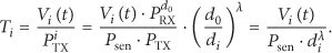
By combining (16) and (11), the lifetime of the ith monitoring node is rewritten as follows:
The lifetime of the surveillance sensor network is determined by the position of the omnirobot. In the surveillance sensor network, the battery voltage is updated periodically. The position of the ith monitoring node in the global coordinator system XOY which is donated as (
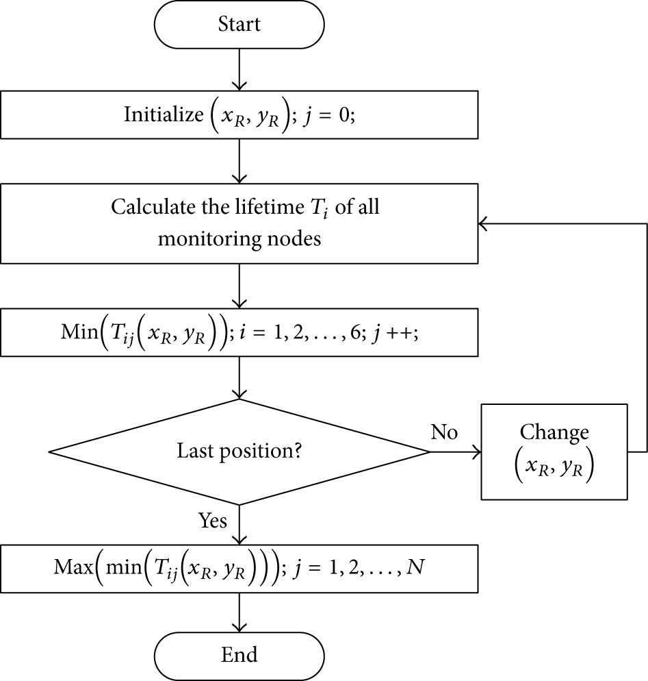
The approach of the position estimation of the omnirobots.
7. Experimental Results
7.1. Transmission Power Estimation
In indoor environments, the distance and ambient conditions have great impacts on the received power of the ZigBee transceiver. The results of the proposed transmission power adaptive method also are influenced. Firstly, an experiment has been done to figure out the influences of the humidity on estimating transmission power. One node is placed in a humidity-controlled box, and the other one is placed at the same height with a 3 m distance. As shown in Figure 11, the LQI is heavily influenced by changing humidity. The LQI is the lowest when the humidity is in the range of 45% to 90%. The transmission power must be configured highly.

The ambient factor (humidity) has great influences on estimating transmission power.
The subsequent experiments were done to figure out the relation between the transmission power and the distance between nodes. As shown in Figure 12, two monitoring nodes were placed in a passageway with a distance of D. Equation (10) is used to calculate the minimum transmission power. In the adaptive transmission power approach, the group decision based method is applied to evaluate the results of estimating transmission power.

A platform is built for testing the transmission power estimation method.

Estimate the minimum transmission power. The red curve is the LQI which is used to measure the received signal strength. The black is the initial estimated results. The blue curve is the final estimated results.
The network lifetime is greatly influenced by the positions of the omnirobots. The position estimation method is simulated. In the simulation program, the parameter λ is set as 4. And the position of each node is fixed as (0, 2), (1.5, 0), (3, 0), (4, 1), (3.5, 3), and (1, 3), respectively. The simulating results are shown in Figure 14. The network lifetime is maximized when the omnirobot is fixed at the position (2, 1.6). When the omnirobot reaches the position, the adaptive transmission power procedure of each node starts. The relation between the voltage and the capacity of the batteries used is shown in Figure 15. The battery voltage difference is only 0.2 V when the capacity is in the range of 5% to 95%. The transmission power of the applied module can only be adjusted with a 6 dBm step. Therefore, the position of the omnirobot does not have to change frequently.

The simulation results of the position estimation of the omnirobots.

The relation between the voltage and capacity of the battery.
7.2. Image Capture and Transmission
The image transmission is one of two important indicators of the proposed surveillance sensor network. The output image dimension of the digital camera can be

Transmission time of different sizes of images in surveillance sensor network.
Figure 17 presents the energy consumption of the monitoring nodes. Compared with reading

The energy consumption of transmitting image with different method and transmission power. The “SE” is short for transmission security mechanism enabled. And the “SD” is short for transmission security mechanism disabled.
As shown in Figure 18, a monitoring node captures 6 images continuously when an intruder is detected. The omnirobot will navigate to the monitoring nodes to collect the images. Therefore, the monitoring nodes can transmit the images with the lowest transmission power. It can save 11.7% of the energy that a

The 6 images are captured by the digital camera continuously when an intruder is detected.
7.3. Network Recovery
The recovering performance of the proposed surveillance sensor network is associated with the route maintaining mechanism. Two means of route maintaining mechanisms are applied in the surveillance sensor network protocol. Several experiments were done to figure out the influence of the maintaining mechanism on the network recovery. It can be seen that a parent node (omnirobot) detects a child node (monitoring node) loss with a 1.9 s delay in Figure 19. If a child node is not damaged, it takes 5.2 s to rejoin the surveillance sensor network. The child node considers the parent node to be lost when the number of failed messages reaches the default number. The child node can be aware of a parent node loss with a 5.5 s delay. The time can be reduced through decreasing the number of the maximum failed packets and the polling period. The omnirobot reestablishes the network in about 2.7 s. The maximum awareness time of a node loss is 5.5 s. And the time of the child node rejoining the surveillance sensor network and the parent node reforming the surveillance sensor network is less than 2.7 s. To sum up, the surveillance sensor network can be conscious of the node loss and self-recover timely.
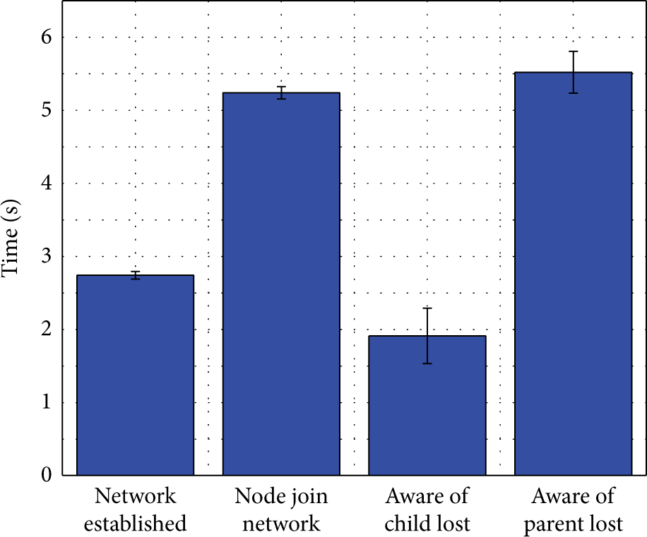
The self-recovery performance of the surveillance sensor network.
8. Conclusions
The energy-efficient transmission method of the surveillance sensor network which contains omnirobots and monitoring nodes is presented in this paper. The surveillance sensor network architecture and monitoring node hardware are designed and optimized with the consideration of the energy consumption. The omnirobots and monitoring nodes form several star-like sensor networks which are in charge of the house. The omnirobots send the data collected from the monitoring nodes to the home server for recording. The static monitoring nodes mounted above the entrances sleep/wake up cyclically. They also can be triggered to capture images when the equipped PIR sensor detects intruders. Based on the proposed adaptive transmission power approach, the monitoring nodes can adjust the transmission power based on the distance between the omnirobot and the monitoring nodes. Furthermore, a method is designed for determining the position of the omnirobots to prolong the lifetime of the surveillance sensor network. Several experiments have been done to evaluate the performance of the proposed surveillance sensor network. The transmission power can be minimized sufficiently through the adaptive transmission power approach. A 160 × 120 image can be transmitted by the monitoring nodes within 2.1 s. And it can save 11.7% of the energy that an image is transmitted with the lowest transmission power, and the energy consumption of transmitting images without transmission security mechanism is reduced by 21%. The surveillance sensor network can be conscious of the node loss and self-recover timely.
Footnotes
Conflict of Interests
The authors declare that there is no conflict of interests regarding the publication of this paper.
Acknowledgments
The research reported in this paper was carried out at the Robotic Sensor and Control Lab, School of Instrument Science and Engineering, Southeast University, Nanjing, China. The authors thank all the members of the Robotic Sensor and Control Lab for their great supports. This work was supported in part by Natural Science Foundation of China under Grant 61375076, Natural Science Foundation of Jiangsu Province under Grant BK2011254, Research & Innovation Program for Graduate Student in Universities of Jiangsu Province under Grant CXLX13-085, the Scientific Research Foundation of Graduate School of Southeast University YBJJ1350, and Fundamental Research Funds for the Central Universities under Grant 2242014R20018.