
Abstract
Real-time location system (RLS) based on RFID is an effective indoor positioning system. The battery-free and low cost UHF passive tags can be attached on almost any objects, which are recognized as the best medium to achieve high precision ranging and positioning for large-scale objects. This paper proposes an indoor range measurement based on multifrequency phase difference of arrival (MF-PDoA) using UHF RFID passive tags and discusses the measurement principle, experiment implementation, and results evaluation in detail. After a theoretical overview of MF-PDoA range measurement principle, it introduces an experimental prototype under EPC C1G2 standard for range measurements. Both our prototype and a commercial off-the-shelf RFID reader have been used to verify the measurement method. We propose a Kalman filter and weighting method to process the measuring data. Experiment results indicate that, in a real environment, this method can effectively improve the ranging accuracy, which lays a foundation to extend the proposed measurement into two to three dimensions indoor object positioning.
1. Introduction
Due to the rapid development of IoT technology, both intelligent devices and smart objects have rushed into our life and greatly affected our lifestyle. In 2020, each individual will be surrounded by over 1000 facilities, which are including not only our smart phones and different kinds of embedded system devices but also numerous articles of daily use with perceptible capability. The progress of large-scale intellectualized devices brings effective digital management challenge along with the convenience. Precise range and location information is the foundation to solve such problem, which is also the key to achieve intelligent control. Many applications would benefit from it such as products detection in large warehouse [1].
Since satellite-based ranging and positioning systems have been widely applied in outdoor environment, plenty of solutions have been proposed for indoor environment. Measurement system using WLAN and inertial sensor mixture signal makes advantage of multiple WLAN access points as anchor nodes to navigate the mobile device, in which the inertial sensors such as accelerometer, gyroscope and magnetometer play a role as auxiliary calculation device to improve the ranging and positioning accuracy [2]. With the development of visible light communication technology (such as Light-Fidelity), mobile devices may have the ability to be navigated with visible light by integrating an optical sensor [3]. Although these solutions can make up the drawback of satellite-based positioning, they are still not applicable to give the range and location information for articles of daily use.
Radio Frequency Identification (RFID) system is considered to be a nonsubstitutable network access tool of the Internet of Things technology. It is generally composed of reader, reader antenna, and tags. According to the method of powering, the tags can be divided into active tag, passive tag, and semipassive tag [4]. Battery-free and low cost passive tags can be attached on almost any items, which are recognized as the best medium to achieve precise ranging and positioning for large-scale objects.
In this paper, we present an indoor ranging measurement for passive RFID system based on multifrequency carrier phase difference of arrival (MF-PDoA). This approach is inspired by the multifrequency radar ranging system that the transmitter detects the distance from a receiver by measuring the phase differences generated from several transmission frequencies [5]. We try as completely as possible to explain the MF-PDoA method including the measurement principle, experiment implementation, and results evaluation. Both Kalman filter and weight data fusion method are applied for data progression. We also develop an experimental prototype under EPC C1G2 standard [6] and use both of our prototype and a commercial off-the-shelf RFID reader to verify the MF-PDoA method. It indicates that, in a real environment, this method can effectively improve the ranging accuracy, which lays a foundation to extend the proposed measurement into two to three dimensions indoor object positioning.
The organization of this paper is as follows. Section 2 shows some related works. The MF-PDoA ranging measurement principle is laid in Section 3. Establishment and implementation of the experimental prototype are in Section 4. Data procession is in Section 5 and results analysis is in Section 6. Section 7 is conclusion.
2. Related Works
The emergence of RFID indoor ranging and positioning technology is in 2000 and can be separated into two categories, which are range measurement methods and range-free measurement methods (see Table 1). Algorithm based on range measurement calculates the distance or angle between the reader and tag to know the target position; a classic system is SpotON [9]. LANDMARC [10] is a popular range-free positioning system, which compares the similarity and relevancy of the target tag to the anchor nodes to indirectly give the target position. In this way, the range-free algorithms need a number of reference tags with known positions. Both of high environment complexity and implementation costs make such methods are not conducive in the practical application.
Performance of the methods.

Excepting our phase-based measurement system, the range measurement approach can be divided into signal time of arrival (ToA), signal time difference of arrival (TDoA), signal angle of arrival (AoA), and received signal strength indicator (RSSI) according to the measuring characteristic information [4]. Indoor environment is a complex multipath Non-Line-of-Sight (NLOS) environment. When using TOA or TDOA methods, the RFID system needs to generate nanosecond level time to ensure the location measurement accuracy, but it is difficult to achieve. In addition, the AoA-based method needs additional hardware like phased array antennas in an open space.
RSSI based methods use Path Loss Model [11] to establish the range measurement model. However, ranging method based on the Path Loss Model cannot be applied mechanically under real environment. Due to the indoor impact on RF reflection and multipath effect, RSSI fluctuation interval generally exists and the measurement is hard to remain at a high accuracy level. To prove this situation, we carry out an experiment by using ImpinJ Speedway R420 UHF commercial off-the-shelf reader, Laird S9028 9 dBi cycle polarization antenna [12], and ImpinJ Monza tag [13]. The tag was planned to move 18 steps from 0.5 m to 4 m, at a step size of 0.2 m, away from the reader antenna. At each position, we collect 200 RSSI samples and demonstrate the RSSI value distribution in Figure 1. It clearly indicates the RSSI fluctuation interval is about 12 dBm. In addition, Figure 2 is the RSSI normalization distribution of two different positions. The distributions are independent of each other. They can either obey Gaussian distribution or not, which all depend on the environment complexity. The randomness of multipath reflection and interference make it even harder to generalize or summarize the relationship between the RSS distribution rule to the tag-to-reader distance. Thus, we aim to use phase based method to give more accurate and precise ranging result.

RSSI distribution versus distance (ImpinJ Monza).

RSSI distribution versus position (ImpinJ Monza).
3. Range Measurement Principle
3.1. RFID Signal Delay Model
The RFID reader transmission carrier wave signal is a continuous wave (CW) signal. The ranging measurement based on phase difference of arrival is to use the phase change of the propagation path between the reader to the tag, corresponding to determine the tag-reader distance.
Figure 3 shows the passive RFID system signal transmission model. In the ideal situation, the reader transmitting signal phase 


RFID system signal transmission model.
3.2. The Phase Difference Ranging Measurement Principle
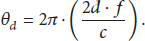
As the formula discussed above, the distance between the reader and tag can be calculated as

However, the reader can only detect the receiving signal phase value
We achieve this by using the concept of phase difference of arrival (PDoA). There are three main techniques based on phase difference of arrival, which are Time Domain PDoA (TD-PDoA), Frequency Domain PDoA (FD-PDoA), and Spatial Domain PDoA (SD-PDoA) in [15]. We adopt the second technology by measuring the phase of the tag signal at multifrequency. The range to tag can be calculated as

However, when in the real environment, the transmitting signal phase is always nonzero. It is dependent on the measurement system hardware characteristics. We define a calibration distance denoted 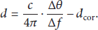
3.3. Extend to 2D Space Positioning
It is possible to extend the MF-PDoA method to 2D or 3D space positioning by using multiple receivers. A multiple input multiple output (MIMO) system consisted of one reader and two antennas for both transmitting and receiving shown in Figure 4. We denote the antenna to reader distance as r the range estimation 

2D positioning model.
4. Prototype Implementation
Range measurement as the foundation of positioning will be discussed later. In this chapter, we firstly describe and simulate the quadrature signal demodulation phase measurement method. Then, we establish our prototype by using an ImpinJ R2000 UHF RFID SoC chip and a FPGA chip which integrates an analogy to digital converter. Physical level quadrature demodulation waves of the tag reflection signal are received by the R2000 RFID front-end chip and the FPGA chip samples the signal strength amplitude to calculate the phase of arrival.
4.1. Phase Simulation
In a typical wireless communication system, the phase measurements include FFT phase detecting method, coherent demodulation method, and so forth. The passive RFID system belongs to zero intermediate frequency system, which means the receiving signal carrier wave frequency is consistent with the local oscillator frequency. By respectively demodulating the quadrature signals with local oscillator signal, we can acquire the phase value and avoid the phase blind spots at the same time. Figure 5 is our simulation system in MATLAB which indicates the quadrature demodulation scheme. Two orthogonal vibration signals, respectively, are demodulated with the receiving signal. The demodulated
Quadrature demodulation system.
Denoting the carrier signal as 


The real modulation frequency and carrier frequency of UHF RFID system are not appropriating for simulating observation. We use lower frequency for the
In our system, all the waves are cosine wave and the phase unit is
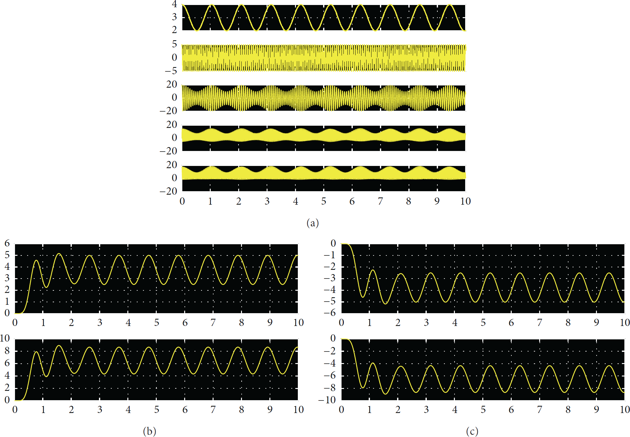
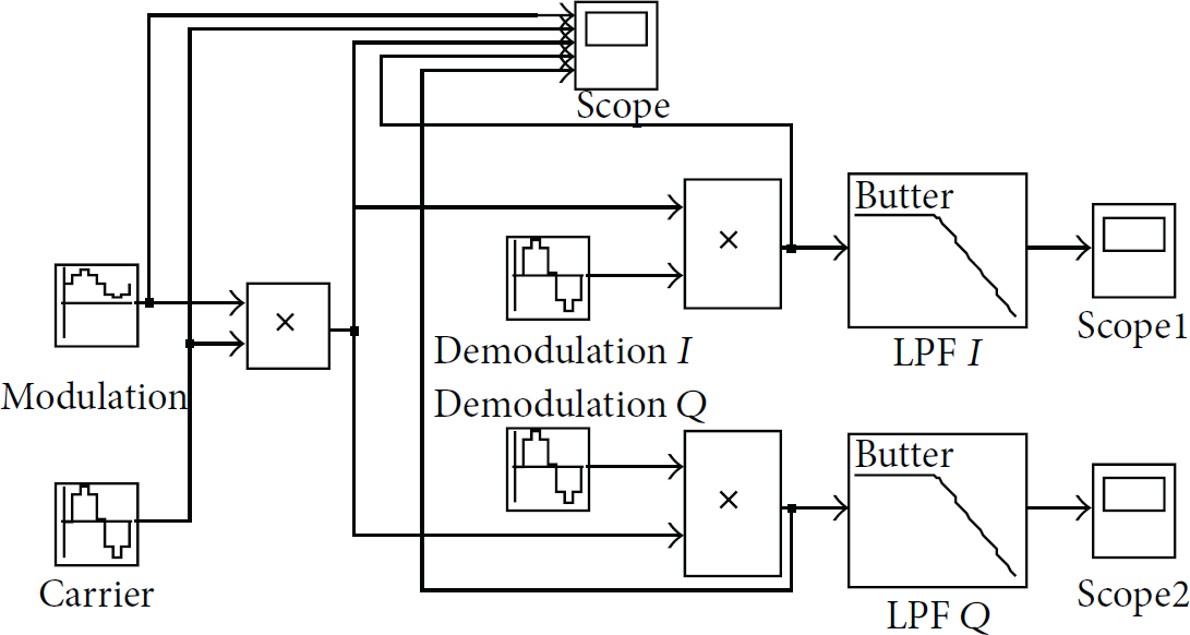
(a) Quadrature demodulation system results in Scope window: the wave form of the modulation wave, carrier wave, AM wave, and the quadrature demodulation wave. (b) The wave form of the quadrature demodulation system results from LBF in Scope1 and Scope2 when the initial phase is 60°. (c) The wave form of the quadrature demodulation system results from LBF in Scope1 and Scope2 when the initial phase is 240°.
By using the Scope data recording function in Simulink, we import the

Phase values simulation.
4.2. Prototype Implementation
ImpinJ Indy R2000 UHF RFID reader chip is a highly integrated, high-performance device for EPC Class1 Gen2 applications. It supports zero intermediate frequency (ZIF) architecture of the worldwide ISM band (the operating frequencies are from 840 MHz to 960 MHz). The Indy R2000 reader chip comprises all of the RF and Baseband blocks to interrogate and receive data from compatible RFID tags. The transmitter supports both in-phase quadrature (

ImpinJ R2000 reader chip top level block diagram.
Indy R2000 chip provides analog test function to observe and analyze quadrature signal. By configuring the internal register (register address x0430 according to the ImpinJ technology support), we can flexibly choose the analog test pin to show the signal wave from LNA or low pass filter directly from the RF front end. The experiment is established in Figure 9(a); despite an oscilloscope, we can see the physical level

(a) The ImpinJ R2000 development board experiment. (b) The protocol configuration parameters. (c)

Zynq hardware structure.

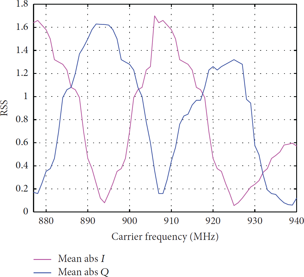
We give the amplitude statistic data in Figure 12 when the tag-to-reader distance is constant along with frequency increasing. We can see that when the frequency is increasing, the receiving signal package is harder to be detected, which decreases the phase sampling accuracy. It is because the output signal from quadrature demodulator is interfered by channel noise. It is desirable to recover RSS sign using the phase information contained in the Baseband signal and a Goertzel's algorithm method to acquire more accurate phase value is put forward in [18, 19]. However, in this paper, we simply choose 900–920 MHz which has a relatively stable RSS value to estimate the distance.
RSS value with frequency increasing.
4.3. Phase Measurement Using Our Prototype
Measurements have been performed by a Larid 9028 9 dBi antenna and ImpinJ Monza tag (see Figure 16). The tag was planned to move 30 steps from 0.5 m to 3.5 m, at a step size of 10 mm, away from the reader antenna. At each position, our prototype uses multiple transmission carrier wave frequencies to collect phase information. At least 200 tag phase values are recorded corresponding to each frequency. Experiment results in Figure 13(a) show the phase distribution when the distance is 2.2 m and the carrier wave frequency is 907 MHz, which indicates the phase values for a same carrier wave frequency obey to Gaussian distribution (normalization processed). Figure 13(b) shows the phase distribution when carrier wave frequency changes from 913 MHz to 920 MHz at 2.2 m. We can see the phase value linearly changes with the carrier wave frequency.

(a) Phase value distribution
Considering the drawback of the arctangent phase acquiring method, the phase ambiguity also exists in our system. When operating the inventory command, we give a phase value pair including a small phase value and a large phase value with π difference at the same time. Although there is no method to directly distinct these numbers as which one is correct, we comprehensively analyze them in context with other frequency phase values. For example, if the phase pairs are 170° and 350° at 915 MHz, 182° and 2° at 916 MHz, and 194° and 14° at 917 MHz, we can use 170°, 182°, and 194° to calculate the phase difference or pick 350°, 2°, and 14° with the same effect. On the other hand, the advantage of R2000 chip is the long selectable carrier frequency range, from 840 MHz to 960 MHz, which supplies us with an opportunity to collect phase value from more frequency channels.
5. Measurement Data Procession
Now, by establishing the phase measurement prototype, arrival phase value of the tag reflecting signal can be detected. Before developing the range measurement experiment, Kalman filter has been used to calibrate the phase difference value (see Figure 15). A weight data fusion method has also been proposed to improve the range estimation accuracy and system robustness.
5.1. Kalman Filter Phase Difference Calibration
We use multifrequency to obtain multiple phase difference value. The frequency separation can be either the same or not. According to the phase sampling deviation and the complex multipath interference, the phase difference values are floating as in Figure 13(b). To improve the ranging accuracy, we use Kalman filter to calibrate the phase difference value. Kalman filter [20] is wildly used in discrete data linear filtering problem. Our passive RFID PDoA range measurement system can be abstracted to a linear stochastic differential system and use Kalman filter to obtain an optimum phase difference from the multiple phase values to improve the measuring accuracy. Denote the carrier frequency is 
According to Kalman Filter theory, 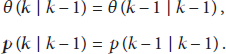

By giving the initial values
Kalman filter (12) to (13) is used to estimate an optimum phase difference. The initial value

Influence of Kalman filter.
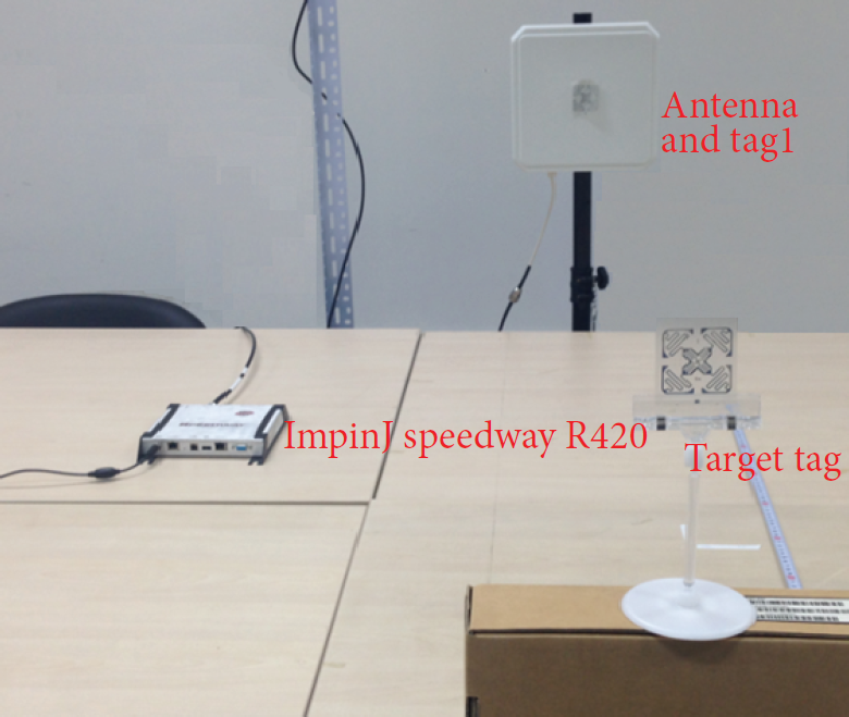
ImpinJ R420 reader range measurement experiment.

Ranging results of our prototype (ImpinJ Monza).
5.2. Weight Data Fusion Distance Calibration
If we separate the phase difference values into several clusters according to the frequency difference to calculate distance, a group of range estimation results can be fused to improve the robustness against noise and system propagation characteristics. Unlike the fixed frequency separation in [18], we propose to use different frequency separation to have varying level of range estimation quality. It is desirable to have weighted average of the range estimation rather than simple averaging. For our prototype, we choose the largest frequency pair variation as 4 MHz and ambiguity range issue will not happen in our experiment.
Estimation volume is the fusion distance 
According to [21], the range estimates using the frequency pairs with larger separations are insensitive to noise and thereby have higher estimation accuracy. Therefore, the weight of the large separation pair could take a higher value in the fusion to improve the accuracy. In particular, we give the weight data as

5.3. Calibration Distance Estimation
As mentioned above, when, in the real environment, the transmitting signal phase is always nonzero, it is incorporated in environment calibration distance
6. Experiment Implementation and Results
Measurements have been performed using a Larid 9028 9 dBi antenna and an ImpinJ Monza tag pair. Excepting our prototype, we also use a commercial off-the-shelf UHF RFID reader ImpinJ speedway R420 without any hardware or firmware modification to do the range measurement experiment. By adopting LLRP communication protocol [22] and enabling the extension parameters, the ImpinJ reader can support the phase report with the received information package [23]. We adjust the reader configuration to immediately report reading whenever tag is detected. The software is implemented using C#. It has a same phase sampling precision with our prototype. However, according to the regulatory region control and the firmware configuration, we can only use Chinese region to operate 16 fixable frequency channels from 920.625 MHz to 924.375 MHz with 250 kHz step.
The communication protocol parameter configuration is mostly unchanged as described in Figure 9(b) without
We use the root mean square deviation (RMSD) [24] to measure the accuracy of tag estimation range. Where N is the total estimation number, 
To analyze the performance, we compare with the exiting ranging and positioning method like LANDMARK, SpotON, and SAW mentioned in [4]. Popularity, standardization, and performance are considered to choose the reference algorithms. The average calculation distance of our prototype is 3.385 m and 3.16 m for R420 system. The RMSD of the ranging estimation of our prototype from 0.5 m to 3.5 m is 13.5 cm with minimum error 1.3 cm, while the accuracy of R420 is 15 cm with minimum 6 cm. Better accuracy of our prototype is benefit from a larger number of phase sampling from more frequency channels. Ranging inaccuracy is caused by the phase sampling deviation, imperfect hardware,
7. Conclusion
In this paper, we have focused on the multifrequency phase difference of arrival range measurement method for passive UHF RFID system. We try as completely as possible to explain the experiment implementation and results evaluation. Both Kalman filter and weight data fusion method are applied for data progression. Experiment results indicate that MF-PDoA method has a certain uniformity and generality with better ranging accuracy. The future work is to use multiple transmission reader antennas and expands this range measurement to 2D and 3D space indoor localization. Multiple target tags and moving tag scenario will also be considered. Large-scale objects ranging and positioning involved applications like products detection in large warehouse would benefit from it.
Footnotes
Conflict of Interests
The authors declare that there is no conflict of interests regarding the publication of this paper.
Acknowledgment
This research is supported by Beijing Natural Science Foundation (no. 4122010) and Beijing Science and Technology Innovation Platform Program (nos. PXM2014 _014204_07_000049, PXM2015_014204_500211).