
Abstract
Dynamic characteristics of structures have been monitored for safe operation and efficient maintenance of large civil infrastructures. For vibration data measurement, the conventional system uses cables, which cause very expensive costs and inconvenient installation. Therefore, various wireless sensor nodes have been developed to replace the conventional wired system. However, there still remain lots of issues to be resolved such as time synchronization between sensor nodes, data loss, data security, and power supply. In this study, Smart One-Channel Sensor Node (SOSN) was developed to measure vibration data, which can practically solve the issues on installation, time synchronization, and data storage. It is designed for temporal measurement with a limited capacity to operate for several hours using embedded batteries. Laboratory tests were carried out to verify the performance of the developed SOSN compared with conventional wired system. Its practical advantages were investigated through three full-scale tests on large civil infrastructures. Three field applications revealed that SOSN is a very practical tool for short-term monitoring of large civil infrastructures with respect to traffic control, installation time and convenience, secure data gathering, and so forth.
1. Introduction
Structural health monitoring (SHM) has been an emerging topic as construction of large civil infrastructures increases and existing structures get deteriorated. Notable examples of SHM application include the monitoring systems installed in Humber Bridge in the UK [1], Tsing Ma in Hong-Kong [2], and new TV tower in Guangzhou [3]. Throughout the years, SHM has become an efficient mean of structural integrity assessment for effective maintenance, repair, and retrofit planning of civil infrastructures.
SHM can be classified into two groups: (1) short-term monitoring for temporal inspection of structures and (2) long-term monitoring for continuous or periodic investigation of structures. While long-term monitoring system is implemented to a few structures of high importance such as long span cable bridges, nuclear power plants, and high-rise buildings, it is also essential to carry out short-term monitoring for most civil structures of moderate importance. Maintenance guidelines suggest that maintenance agencies should perform various levels of inspection periodically, for example, regular inspection every 2 years and in-depth inspection every 5 years for bridges in Korea.
Among well-known SHM techniques, vibration tests can be easily and economically conducted to identify dynamic characteristics of structures such as natural frequencies, mode shapes, and damping ratios [4]. Vibration tests are generally classified to forced vibration tests (FVTs) and ambient vibration tests (AVTs). FVTs usually require expensive equipment and controlled operating conditions. Meanwhile, AVTs can be conducted under normal operating conditions with uncontrollable and immeasurable ambient loads such as traffic and wind. AVTs have been carried out for various civil infrastructures such as bridges [5, 6], dams [7, 8], and buildings [9].
For periodic or temporal inspection, sensors are temporarily installed at structures to measure the structural responses. Installation of wired sensors in large structures can pose several difficulties including labor-intensive work for cabling which increases the installation cost and partial or full blockage of traffic during sensor installation which can cause inconvenience to the public.
In recent years, researchers have developed a wide variety of wireless sensors to overcome the disadvantages of the wired sensor systems. Straser and Kiremidjian developed a wireless modular monitoring system (WiMMS) to reduce installation costs and labor-intensive works in the field test of large civil structures. Since this first effort, various wireless sensor platforms with advanced hardware and software have emerged [10]. In 2001, Berkeley Mote Hardware developed Mica, a wireless sensor network equipped with an improved memory capacity and a faster microprocessor. Subsequent improvements to the MICA platform resulted in Mica2, Mica2Dot, and Micaz which were commercially available through Crossbow Technology, Inc. (2007) [11]. Intel developed Imote2, which provides enhanced computation and communication capabilities. Imote2 is able to run resource-demanding sensor network applications, while maintaining efficient power management and small size [12]. In addition, Narada is a low-cost wireless sensor platform developed at the University of Michigan from commercial off-the-shelf embedded system components for use in monitoring civil infrastructure systems [13]. While these wireless sensors have shown great potential for structural health monitoring and assessment of civil infrastructure, critical issues such as reliable communication, accurate network-wide time synchronization, sufficient sensing capabilities, and limited power are yet to be completely resolved [14].
Research efforts have been significantly devoted to address the wireless communication-related issues. Nagayama et al. investigated the effect of data loss that was shown to have significant impacts on the data processing results [14]. Nagayama and Spencer developed a reliable wireless communication protocol that ensures all packets transmitted without loss by resending lost packets [12]. An alternative approach is to employ wireless sensor's onboard computing capability that performs in-network data processing to extract essential information such as structural damage locations from raw sensor data and subsequently be collected at the central base station [14–16]. As the size of extracted information is smaller than the raw data, this approach can significantly reduce the wireless communication, resulting in increased reliability as well as reduced battery consumption. However, the raw sensor data, which cannot be recovered from the processed data, is often desired, particularly when necessary features regarding structural conditions are not previously known.
Another important issue in the wireless sensor network is time synchronization between sensor nodes. The lack of a global clock for the wireless sensor network poses a big challenge on obtaining accurate data from the system. For instance, when modal analysis is performed using the data from sensor nodes with nonsynchronized local clocks, the mode shapes will be possibly inaccurate due to the phase delay, which can provide false condition assessment of a structure. Currently, several techniques have been proposed to resolve the issues related to time synchronization. Elson et al. proposed a synchronization protocol for sensor networks referred to as Reference Broadcast Synchronization (RBS) based on the receiver-receiver synchronization [17]. Ganeriwal et al. presented a network-wide clock synchronization protocol, Timing-Synch Protocol for Sensor Networks (TPSN), which relies on the traditional approach of sender-receiver synchronization [18]. Maróti et al. developed Flooding Time Synchronization Protocol (FTSP) to attain a network-wide synchronization of the local clocks of participating nodes by using multihop synchronization [19]. However, it is still difficult for the wireless sensor networks to achieve time synchronization using wireless communication. Furthermore, clocks using cheap crystal oscillator have low accuracy which results in sensor drifting with respect to each other and requires continuous synchronization in order to maintain constant operation time [14].
This study developed a new sensor platform, Smart One-Channel Sensor Node (SOSN), to provide a practical means for short-term dynamic testing of civil infrastructures. SOSN is designed to have combined advantages of both wired and wireless sensor systems such as reliable data acquisition, cost-effectiveness, and convenient installation. SOSN features high fidelity sensing capability, time synchronized sensing with a real-time clock (RTC), and several hours of long data acquisition enabled by reliable hardware control and high-speed flash memory. Laboratory experiments are conducted to validate the effectiveness of SOSN by comparing with the conventional wired system. Also, three full-scale tests on large civil infrastructures were carried out. Three test structures are (1) a highway bridge with steel girders, where traffic control is very limited, (2) a dam, whose physical size is also challenging for the conventional systems, and (3) a steel box girder bridge, where the wireless data communication or cabling along the inside of box girders is impractical and extremely labor-intensive, if possible. Natural frequencies and mode shapes were identified from ambient vibration data and compared with the results from finite element analysis to show the reliability of the SOSN.
2. Development of Smart One-Channel Sensor Node
2.1. Overview
The wired and the wireless sensor systems both have advantages and disadvantages in terms of reliable data collection, cost-effectiveness, and installation convenience. While the wired system can generally retrieve all sensor data without data loss, installing sensor nodes and central data logger is labor-intensive and time-consuming mainly due to cabling. Thus, despite the highest reliability, the wired system is considered to be impractical for the short-term dynamic testing such as regular bridge inspections. In contrary, the wireless sensor system minimizes the time and effort required for sensor installation. However, the wireless sensor intrinsically suffers from unreliable data communication and hardware instability. Both wired and wireless systems do not seem to provide a practical solution for the short-term dynamic testing of large civil infrastructures.
The Smart One-Channel Sensor Node (SOSN) developed in this study combines the robustness of the wired system associated with its reliable data acquisition and the convenience of the wireless system in the sensor installation and management. To take the advantages of both wired and wireless systems, SOSN adopts three primary features: (1) robust data acquisition enabled by saving whole sensor data in the memory space of each SOSN, which can be retrieved with a wired connection after all measurements, (2) time synchronization by a built-in RTC in each sensor node, and (3) wireless communication capability for sensor status check and data verification. SOSN is composed of three functional subsystems: sensing interface, computational core, and wireless transceiver. The “sensing interface” includes an interface to which only ICP (Integrated Circuit Piezoelectric) type accelerometer is used for measuring the acceleration signals. The “computational core” consists of a microcontroller for computational tasks and system operations with embedded algorithms. The “wireless transceiver” is an integral component of the wireless system, composed of RF transceiver, a transformer, and an antenna to communicate with the base station. Figure 1 and Table 1 show the developed SOSN and its specification compared with other wireless sensor nodes. Note that the SOSN has similar performance with Imote2, while having long communication range and expandable flash memory storage. Several critical features on the hardware and software will be further addressed in the following sections.
Specifications of various wireless sensor nodes [12].


The developed Smart One-Channel Sensor Node.
Figure 2 shows the implementation procedures of SOSNs in the field applications. At first, measurement location is determined and all SOSN units are prepared by assembling accelerometer, SOSN, leveling base plate, and so forth. Data acquisition parameters including sampling frequency, filter option, and measurement duration are set up by receiving a message from a laptop computer. Time synchronization for all SOSNs should be done just before measurement starts. Each SOSN is deployed at the measurement location very quickly. When each SOSN is placed at the predetermined measurement location, it gathers vibration data of structures. While measuring data, a field engineer can check the status of sensor node and signals by carrying a laptop computer with control and monitoring software. If a malfunction is detected, the sensor unit (accelerometer and SOSN) will be replaced with another unit. Finally, ambient vibration measurement can be carried out with the well-functioning SOSNs. Raw data involves inevitable noise in the first part of signal, because sensor deployment requires some time. Therefore, it is required to cut the first noisy parts out from the raw data considering deployment time.

Implementation procedures of SOSNs in field test.
2.2. Reliable Data Acquisition with Real-Time Visualization
SOSN is designed to be capable of robust data acquisition by saving all raw data in each sensor node that can be retrieved with a USB cable directly connected to a PC after the measurement. This strategy is especially useful in the short-term dynamic testing that does not necessarily require real-time data processing. Rather than using relatively unreliable wireless communication, saving measured data directly in the memory space of each node can ensure data collection without loss and be thus more practical than wireless sensors in the short-term field testing for large civil structures.
To enable large data to be measured and stored, the hardware and software development of SOSN is focused on the sufficient memory space and the system stability. The SOSN allows measured data to be stored on a high-speed flash memory with sufficient memory space; for example, 8 GB flash memory can store dynamic data with 256 Hz sampling frequency for about 600 hours. It is designed for temporal measurement, not long-term monitoring, since it can be operated for several hours using embedded batteries.
In case of malfunction in the measurement system, each sensor or sensor node in the system should be easily replaced. For the purpose of on-site data checking, each sensor node transmits measured data at a downsampled frequency of 20 Hz while saving the raw data directly to a flash memory. Real-time visualization can be made channel by channel at a laptop computer connected to a receiver node. Figure 3 shows the developed software to setup SOSN and to monitor the measured data in real-time manner. The software is designed for a field engineer to check the signal from each sensor node by carrying a tablet PC to a sensor location. This is very practical especially for the applications of large civil infrastructures.

The control and monitoring software for SOSN.
2.3. RTC as an Alternative to Time Synchronization
Typically, it is difficult for wireless sensor networks to achieve time synchronization due to limited energy, computing power, and memory on a sensor node. Furthermore, time information provided by a microcontroller has low accuracy which results in data drifting with respect to each other and requires continuous synchronization in order to maintain sufficient time synchronization performance. Moreover, wireless data transmission in large civil structures such as bridges and dams may not be affordable as the sensors are located too far from each other.
The developed SOSN is basically timely synchronized one-channel data acquisition system, which is very practical for short-term monitoring of large structures. It uses RTC Module with embedded crystal, RV-3049-C2 (http://www.golledge.com/), to achieve sufficient time synchronization performance for short-term monitoring of civil structures.
Table 2 summarizes critical features of the RTC module. It has a 4-wire serial interface and offers temperature compensated time with high time accuracy of ±6 ppm (parts per minute) at −40°C to +85°C and ±8 ppm at −40°C to +125°C. Note that the effect of time deviation of RTCs needs to be investigated considering the specific application.
Specification of RTC embedded in the SOSN.

3. Laboratory Experiment
3.1. Test for Time Synchronization
The time synchronization error will contribute to estimation error of the dynamic characteristics of the structures. Short-term dynamic testing of civil structures usually takes less than several hours depending on the dynamic characteristics of the test structures and ambient excitation sources. When the structures are well excited by the ambient inputs, it will require relatively short measurement duration to extract dynamic characteristics of structures. For the structures with very long natural period, it requires relatively long measurement data.
The performance of time synchronization and measurement reliability was investigated through a shaking table test as shown in Figure 4. The test specimen is a steel plate with a dimension of 30 cm × 15 cm × 0.2 cm. The plate was excited by a sinusoidal input at 20-minute interval for 180 minutes. Acceleration responses were measured using four piezoelectric accelerometers (ULT2015, http://www.lancetec.com/) installed on the top of the plate with a sampling rate of 256 Hz.
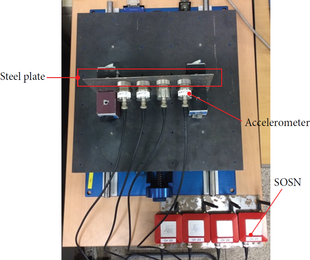
Laboratory test for time synchronization error.
Figure 5 shows the measured signals together with the zoomed images at every hour. It is shown that all four signals are timely synchronized at the beginning, but the time lags among signals increased as measurement duration increased. Table 3 summarized the maximum time lag at every hour compared with the maximum allowable RTC deviation. To draw more general result on the performance of time synchronization, the maximum time lag among 16 SOSNs for 1-hour data was investigated 20 times. The maximum time lag was found to be 7.8 ms which is less than the allowable RTC deviation in 1 hour. From this result, it can be found that the performance of time synchronization of SOSN is acceptable within the level of maximum allowable RTC deviation.
The time lag of measured signals.


Measured signals from shaking table tests.
3.2. Comparison between Smart One-Channel Sensor Node and Wired System
A shaking table test was carried out to validate the performance of SOSN compared with the conventional wired sensor system as shown in Figure 6. Wired systems are composed of the commercially available data acquisition systems: NI-SCXI-1531 for 8-channel accelerometer module and NI-SCXI-1600 for data acquisition and control module (http://www.ni.com/).

Laboratory test setup.
The shaking table was excited by a combined harmonic signal with three frequency components of 0.8, 2.1, and 4 Hz as shown in Figure 7. Figure 8 shows the measured data from SOSN and wired system. It showed perfect agreements at the excited frequencies and some discrepancies at the unexcited frequencies. This is due to inherent dynamic characteristics of data acquisition systems, measurement noise, noise to signal ratio, and so forth.

Input signal with three harmonic components.

Measured data from SOSN and wired system.
4. Field Experiment
4.1. Steel Plate Girder Bridge
Ambient vibration test (AVT) was carried out on the Medina River Bridge (built in 1937) shown in Figure 9. The bridge consists of three parts: 4@48′ (SPG), 273.33′ (74′–2′′ + 125 + 74′–2′′, Gerber), and 4@50′–2′′ (SPG). The AVT was conducted in the middle part of the Gerber Bridge, where Gerber joints are located at one-quarter and three-quarters of midspan. The bridge is located along the northbound interstate 35 and has two traffic lanes. Since interstate highway carries heavy daily traffic, traffic control is an important issue to be considered. Moreover, it is impossible to install sensors at the bottom side of the bridge deck, since the test bridge crosses over the Medina River. Therefore, instrumentation time is of great concern to field engineers.

Overview of the Medina River Bridge.
The SOSNs with piezoelectric accelerometers (ULT2015, http://www.lancetec.com/) were utilized to measure ambient vibration of the bridge. Figure 10 shows sensor layout for 26 accelerometers installed on the bridge. Figure 11 shows the sensor deployment procedures. Firstly, the 1st lane was temporarily closed and 13 accelerometers were installed along the curb. Then the 1st lane was reopened to traffic, while rubber traffic cones remained along the borderline of the curb to protect the sensors. Afterwards, the shoulder and half of the 2nd lane were closed and 13 sensors were installed. All SOSNs were initialized before deployment, and sensor deployment took less than one hour. During sensor installation, one lane was kept open to traffic.

Sensor layout.

Deployment of SOSNs.
Ambient vibration in the vertical direction due to normal traffic was measured for 110 minutes at a sampling frequency of 256 Hz. Figure 12 plots the measured acceleration signals and their corresponding Power Spectrum Density (PSD) functions. Frequency Domain Decomposition (FDD) [20] and Stochastic Subspace Identification (SSI) [21] methods were used for output-only modal analysis. For FDD, fast Fourier transform (FFT) analyses were conducted using 4096 data points with a Hanning window and 50% overlapping. Figure 13 plots the 1st singular value and stabilization chart obtained by the FDD and SSI methods, respectively. The first 5 dominant modes are shown in Figure 14. To prove the reliability of AVT results, the results of numerical modal analysis were also suggested. For the analysis, the test bridge was modeled using commercial finite element analysis software based on drawings. Concrete slab was modeled using shell elements; girders and cross beams were modeled using frame elements. From the comparison results, it can be concluded that the dynamic characteristics of the highway bridge can be obtained by SOSNs very effectively in terms of sensor installation and traffic control.
Measured acceleration data and corresponding Power Spectrum Density (PSD).

1st singular value and stabilization chart obtained by FDD and SSI.
Test results: natural frequencies and mode shapes.
4.2. Gravity Dam
The second application example is a dam, whose physical size is challenging for the conventional measurement systems. As shown in Figure 15, the height and crest length of the dam are 97.5 m and 464.0 m. For the wired system, the longest cable can be longer than 200 m, when the data acquisition system locates at center of the dam crest. Also, direct data transmission through wireless communication is difficult to achieve, because the communication range of commercial wireless sensor node is ~200 m. When direct communication is not possible, more complex network topology should be carefully chosen to ensure reliable network sensing for large structures.

Overview of the tested dam.
The SOSN does not require wireless data transmission for measuring the data and it stores all data at its own memory space. This guarantees secure data acquisition while maintaining the advantage of wireless system. Ambient vibration tests were carried out using 24 SOSNs. All sensors were equally spaced and distributed along the dam crest in the transverse direction as shown in Figure 16.

Sensor layout.
The acceleration data were measured for 180 minutes at a sampling frequency of 512 Hz. The dam is subjected to the horizontal external loads such as water pressure and wind load. The measured acceleration data were processed to obtain modal properties using the FDD and SSI methods. Figure 17 plots the first singular value and the stabilization chart obtained by the FDD and SSI methods, respectively. No dominant peaks were seen at the plot, because the dam has higher damping characteristics resulting from the reservoir-structure interaction. However, two modes at 5.28 and 7.12 Hz were successfully identified and the analysis results were also suggested for the purpose of comparison as shown in Figure 18. It has been found that the dynamic characteristics of large civil infrastructures such as a dam can be obtained by SOSNs very effectively, because the conventional sensing systems cannot provide a practical solution due to cabling and wireless communication range.

1st singular value and stabilization chart obtained by FDD and SSI.

Test results: natural frequencies and mode shapes.
4.3. Steel Box Girder Bridge
The last application example is a three-span continuous bridge with steel box girders shown in Figure 19. The test bridge has heavy daily traffic, since it is located along an arterial road in Korea. So it was planned to have the sensors installed along the inside of the box girders. However, cabling is severely labor-intensive and wireless communication is definitely impossible. The SOSN can be an effective alternative to this case.
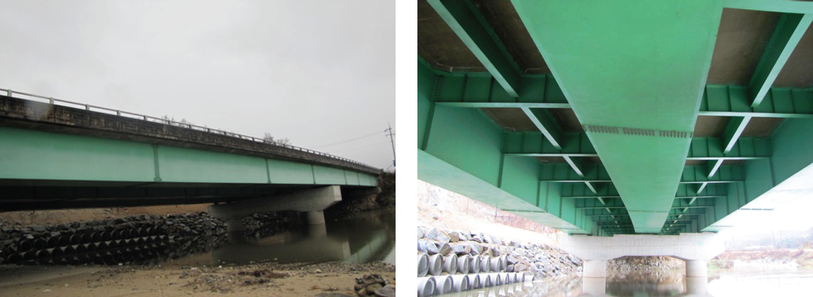
The tested bridge: three-span steel box girder bridge.
Eighteen sensors connected to SOSNs were prepared at the outside of the bridge. Then, the sensors were distributed to measurement locations inside the box girders as shown in Figures 20 and 21.

Sensor layout.

Installation of SOSNs.
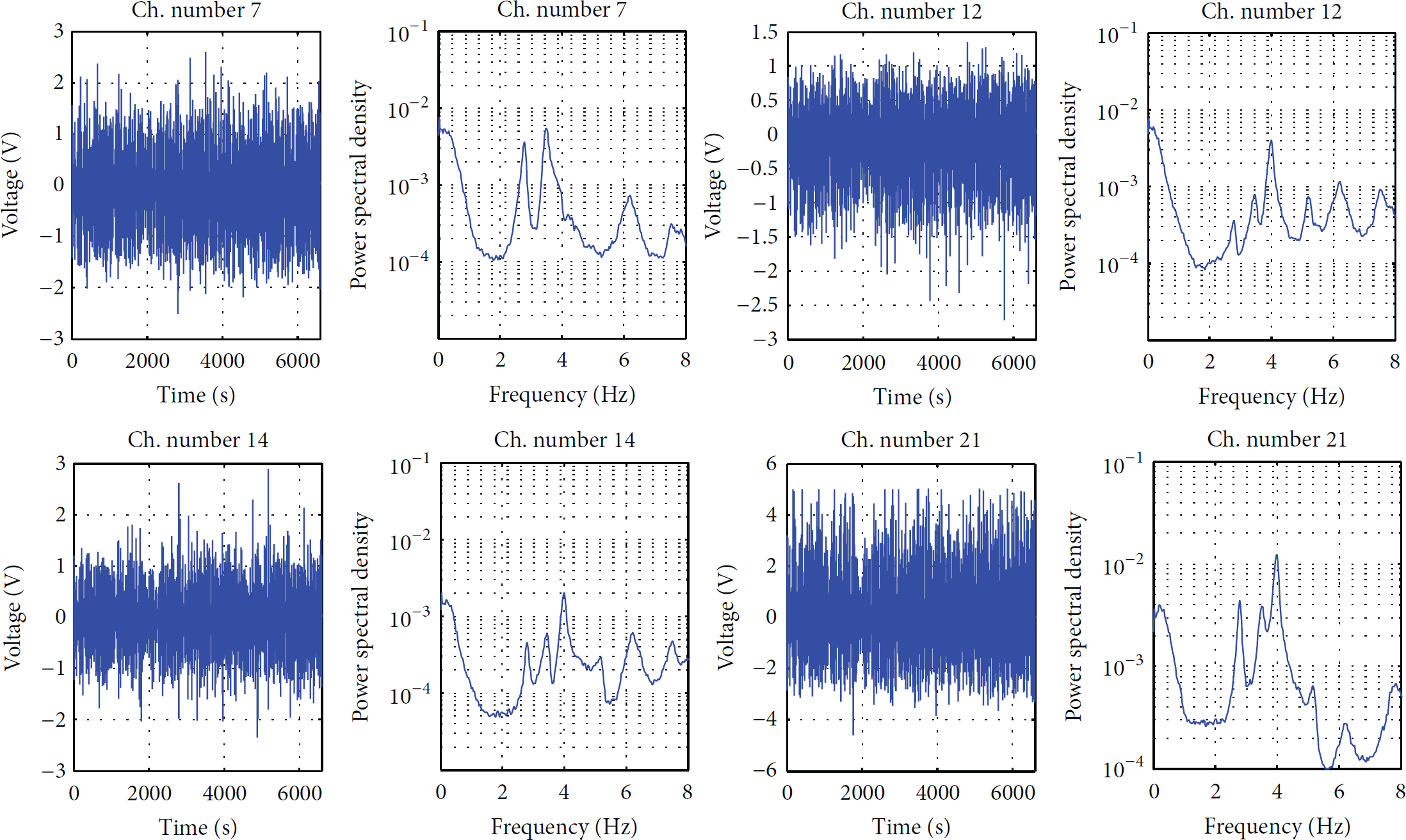
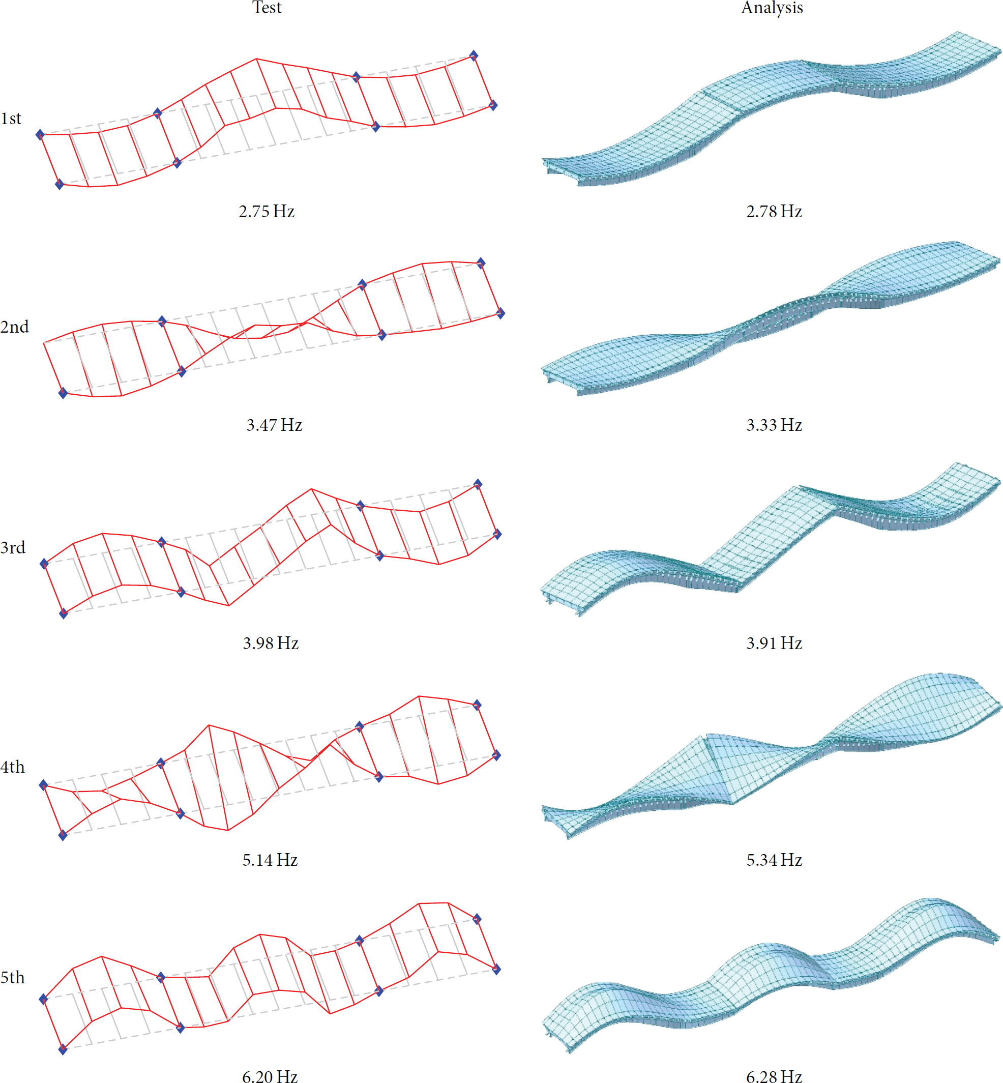
The ambient vibration due to normal traffic load was measured for 60 minutes with a sampling frequency of 256 Hz. Figure 22 shows several examples of measured acceleration signals and their corresponding power spectral density functions. Figure 23 plots the 1st singular value and stabilization chart. The first three modes of the bridge were identified as shown in Figure 24, and the results of numerical analysis were also provided for the purpose of comparison. Although there are about 10% errors in the natural frequencies, general trends showed a close match, for example, the sequence of modes and mode shapes. The error was mainly due to the modeling error, since the tested bridge was severely deteriorated. From these results, it has been shown that the SOSNs can be successfully utilized for short-term monitoring of a bridge in a harsh measurement condition.

Measured acceleration data and corresponding Power Spectrum Density (PSD).

1st singular value and stabilization chart obtained by FDD and SSI.

Test results: natural frequencies and mode shapes.
5. Conclusions
In this study, Smart One-Channel Sensor Node (SOSN) was developed to measure the acceleration data of large civil structures for short-term structural health monitoring. The developed SOSN solves the problems of wireless systems related to time synchronization and data loss by using high precision RTC clock and SD card storage, respectively. The SOSN is developed to have combined advantages of both wired and wireless sensor systems such as reliable data acquisition, cost-effectiveness, and installation convenience.
Laboratory tests were performed to verify the performance of the developed SOSN through shaking table tests. The key features of SOSN are reliable data acquisition and time synchronization that performs in a manner very similar to wired sensor systems. The time synchronization of SOSN was found to be acceptable within the level of maximum allowable RTC deviation. The measured data from SOSN showed a very good agreement with the data from the conventional wired system.
The performance of SOSN was successfully demonstrated by several full-scale tests on large civil infrastructures. The dynamic characteristics of structures were identified based on the ambient vibration data and compared with the analysis results. For the steel-girder highway bridge, where traffic control is very limited due to heavy daily traffic volume, the SOSNs required less installation time and minimized traffic control. As to the second case, the physical size of a dam resulted in bad workability in cabling and poor wireless data communication. 24 SOSNs were easily installed along the dam crest and measured ambient vibration for three hours. While measuring data, the signal from each SOSN was checked by a field engineer. The last case is a steel box girder bridge, where the cabling along the inside of box girders is extremely labor-intensive. All sensors were prepared at the outside of the bridge and disposed inside the box girders. Disposal of all sensors took very short time and the ambient vibration data were successfully obtained by using 18 SOSNs.
From these results, it can be concluded that the developed SOSN can be a useful tool for dynamic testing of large civil infrastructures with low frequency contents, since it can always guarantee the data to be saved with acceptable time synchronization error, even under harsh measurement conditions.
Footnotes
Conflict of Interests
The authors declare that there is no conflict of interests regarding the publication of this paper.
Acknowledgments
This research was supported by a grant (13SCIPA01) from Smart Civil Infrastructure Research Program funded by Ministry of Land, Infrastructure and Transport (MOLIT) of Korea government and Korea Agency for Infrastructure Technology Advancement (KAIA).