
Abstract
The On-Demand Multicast Routing Protocol (ODMRP) is a multicast routing protocol for mobile ad hoc networks (MANETs). Its efficiency, simplicity, and robustness against mobility render it one of the most widely used MANET multicast protocols. In this paper, we present an Adaptive On-Demand Multicast Routing Protocol (A-ODMRP), an improved version of ODMRP. ODMRP lacks a control mechanism for the physical layer. Nodes in ODMRP transmit multicast data at a fixed transmission rate and power level for the physical layer. Also, as the number of nodes belonging to the forwarding group increases, there is significant packet drop or retransmission due to interference between the nodes that send multicast data. However, A-ODMRP implements an adaptive control mechanism with a cross-layer algorithm for the physical layer. When a node transmits multicast data, A-ODMRP can adjust the transmission rate and power level of the physical layer to minimize packet drop or retransmission due to interference between nodes belonging to the forwarding group. Simulation results confirmed that A-ODMRP provides an improved goodput of up to 42% compared to ODMRP.
1. Introduction
Access to remote data has been a fundamental application in both fixed and mobile networks. However, distributed data access in MANETs has proved to be a much more difficult problem than in fixed networks due to node mobility and impairment of wireless transmission. Furthermore, it is very difficult to access data in MANETs by multicast over a wireless network. An ad hoc node will elect to interact at different times with different sets of neighboring nodes that are appropriate for the task at hand. It is apparent that this situation can lead to many-to-many opportunistic multicast groups that dynamically form, grow, and dissolve once a goal is achieved.
Multicast routing protocols developed for ad hoc networks operate in an on-demand fashion. The On-Demand Multicast Routing Protocol (ODMRP) [1–3] is a popular implementation. ODMRP relies on periodic floods for route discovery and maintenance. This design is intended to ensure robustness against mobility and unreliable wireless link propagation. ODMRP periodically reconstructs the forwarding group, the set of nodes responsible for forwarding multicast data. However, when a node transmits multicast data, ODMRP does not have a control mechanism for the physical layer. The nodes transmit multicast data at a fixed transmission rate and power level. As the number of nodes belonging to the forwarding group increases, there is serious interference between the nodes that wastes valuable resources, such as channel bandwidth.
In this paper, we propose an Adaptive On-Demand Multicast Routing Protocol (A-ODMRP), an improved version of ODMRP that can solve the above problems. Unlike ODMRP, A-ODMRP has an adaptive control mechanism with a cross-layer algorithm for the physical layer. When a node transmits multicast data, A-ODMRP can adjust the transmission rate and power level of the physical layer to minimize interference between nodes belonging to the forwarding group.
The remainder of this paper is organized as follows. In Section 2, we review the relevant literature in the field. In Section 3, we describe A-ODMRP in detail. Simulation results provided in Section 4 confirm the properties derived in Section 3. We also assess the performance of A-ODMRP here. Finally, in Section 5, we offer some concluding remarks and directions for future research.
2. Related Work
Several multicast routing protocols for ad hoc networks have been proposed in the literature [4].
The Ad Hoc Multicast Routing Protocol (AMRoute) [5] is a tree-based multicast routing protocol for mobile ad hoc networks [6]. Using AMRoute, bidirectional unicast tunnels are continuously created between pairs of group members located nearby. Unlike multicast group members, some nodes constituting the unicast tunnel do not support AMRoute. When a packet is directed to a logically adjacent member, it will be sent through a unicast tunnel, and may pass through many routers. The group members forward and replicate multicast traffic along the branches of a virtual tree. Each group has at least one logical core responsible for member management and tree maintenance. The robustness derives from the virtual mesh links used to establish the multicast tree in AMRoute. A core failure does not prevent data flow. AMRoute is efficient because it constructs a shared tree for each group. However, AMRoute relies on the existence of an underlying unicast routing protocol. This protocol can only be used in networks where the set of nodes supports the AMRoute routing function. The major disadvantage of the protocol is that it suffers from temporary loops and creates suboptimal trees in the presence of mobility.
Geographic multicast protocols [7, 8] support a two-tier membership management and forwarding structure. The first tier is based on position information, where a zone structure is built. When a zone has members, a leader is elected on-demand. The leader manages group membership and collects the positions of the members in its zone. In the second tier, the leader has a direct relationship with the source. If the source wishes to send a message, it sends it to the leader. It is then the responsibility of the leader to transfer the message to its members in the group. In this two-tier approach, because message transmission is executed in two phases, there exists the possibility of additional transmissions. Electing a leader on-demand, zone management, and managing empty zones are issues afflicting this approach. Nodes must inform the zone leader of the multicast sessions in which they are involved, resulting in further overhead.
A cluster-based quality of service (QoS) multicast routing protocol has been proposed in [9]. This protocol partitions the network into square clusters, and the node nearest to the center of the cluster is elected the cluster head. A gateway node is selected between adjacent clusters to relay packets when adjacent clusters are beyond the effective transmission range. The gateway forwards a probe packet to the appropriate neighbor cluster until the destination, or an intermediate node with a valid route to the destination, is reached. The destination or the intermediate node selects the optimal route using the best predecessor replacement strategy [10], where the node chooses the next-best predecessor satisfying QoS constraints (delay, cost). In this protocol, only the gateway is responsible for packet forwarding. Thus, the selection of the gateway becomes the key point of this protocol. A drawback of this protocol appears when the network is sparse. In this case, gateway nodes may fail to reach a neighbor cluster head, and the route may not be established.
The core-assisted mesh protocol (CAMP) [11] is a mesh-based multicast routing protocol for mobile ad hoc networks [12]. CAMP is a proactive multicast routing protocol based on shared meshes. The mesh structure provides at least one path from each source to each receiver in the multicast group. CAMP relies on an underlying unicast protocol. Every node maintains a routing table (RT) created by the underlying unicast routing protocol. A multicast routing table (MRT) is based on the RT that contains a set of known groups. CAMP modifies this table when a multicast group joins or leaves the network. Unlike Core-Based Tree (CBT) [13], where all traffic flows through core nodes, the core nodes in CAMP are used to limit the control traffic when receivers are joining multicast groups.
ODMRP is a representative mesh-based multicast protocol that provides richer connectivity among multicast members. By building a mesh and supplying multiple routes, multicast packets can be delivered to destinations in the presence of node movements and topology changes. Moreover, the drawbacks of multicast trees in mobile wireless networks, such as intermittent connectivity, traffic concentration, frequent tree reconfiguration, and nonshortest path in a shared tree, are avoided. To establish a mesh for each multicast group, ODMRP uses the concept of the forwarding group [14]. ODMRP also applies on-demand [15, 16] routing techniques to avoid channel overhead and improve scalability. ODMRP uses a soft-state approach to maintain multicast group members, can reduce overhead due to group maintenance, channel, and storage, and has superior connectivity in mobile wireless networks. Two other proposals related to ODMRP. These are R-ODMRP [2] and MR2-ODMRP [3]. R-ODMRP was proposed to quickly recover a disconnected path, whereas MR2-ODMRP was proposed to improve performance using multiple wireless interfaces.
Excluding ODMRP, these options require an underlying unicast routing scheme. They incur heavy protocol overhead and must be aware of their own position information. They do provide effective performance in static environments, however. Conversely, ODMRP has a simple design and can reduce maintenance overhead as it does not require an underlying unicast routing scheme. It appears to be well-suited to dynamic situations. However, ODMRP does not have a control mechanism for the physical layer. The nodes within ODMRP transmit multicast data at a fixed transmission rate and power level for the physical layer. As the number of nodes belonging to the forwarding group increases, there is significant packet drop or retransmission due to interference between the nodes that send the multicast data. Therefore, in this paper, we propose an improved version of ODMRP.
3. Improving ODMRP
In this section, we extend ODMRP with an adaptive control mechanism for the physical layer. To begin, we review the original ODMRP and then detail the proposed enhancements.
3.1. Overview of ODMRP
Similar to on-demand unicast routing protocols, the ODMRP protocol consists of Query and Reply phases.
Figure 1 shows the on-demand procedure for membership setup and maintenance in ODMRP. When a source has packets to send, it periodically broadcasts a member-soliciting packet, called a Join Query. Upon receiving a nonduplicate Join Query packet, every node in the network stores the upstream node address (i.e., backward learning) in a route table, called Up_NodeID_Table, stores the Join Query in a Message Cache, and rebroadcasts the packet to neighboring nodes. When the Join Query packet arrives at a multicast receiver, the receiver creates a Join Table and broadcasts a Join Table packet to its neighbors. This Join Table packet is relayed back to the source following the learned backward path. The nodes on the reverse path become the forwarding group and set their own forwarding group flag (FG_Flag).

On-demand procedure for membership setup and maintenance.
Figure 2 shows the forwarding group concept underlying ODMRP. The forwarding group nodes deliver data. They rebroadcast the nonduplicate packets destined for the associated multicast group, hence allowing them to be propagated toward the receivers. The forwarding group is the set of nodes responsible for forwarding multicast data, essentially forming a mesh structure between all senders and receivers. Multicast groups A and B share the forwarding group. In ODMRP, a soft-state approach maintains multicast group members; no explicit management message is required to join or leave the group.

Concept underlying the forwarding group.
However, the procedure in ODMRP for membership setup and maintenance has the following problems:
It does not allow a duplicated Join Query in the backward learning procedure. It is thus difficult to find the optimal path. It does not have a control mechanism for the physical layer. The nodes hence transmit multicast data at a fixed transmission rate and power level. As the number of nodes belonging to the forwarding group increases, there is serious interference between the nodes, wasting valuable resources, such as channel bandwidth.
3.2. A-ODMRP
In this paper, we propose A-ODMRP, which resolves the problems in ODMRP described in the previous subsection. A-ODMRP improves both data transfer and path forming processes of ODMRP.
Figure 3 shows the difference in the Join Query process between A-ODMRP and ODMRP. As indicated in Figure 3, when the node in ODMRP receives a Join Query, the node verifies that the packet has been duplicated, updates the routing metric (hop-count), verifies whether to update its routing table or stay, calculates the routing metric of the packet, and rebroadcasts the packet.

Flowchart for handling Join Query (a) of ODMRP and (b) of A-ODMRP.
A-ODMRP uses the new routing metric proposed in this paper, which includes a new feature to address a duplicated Join Query. When a node with A-ODMRP receives a duplicated Join Query, the node compares the old metrics with the new metrics. If the metric of the new Join Query is less than the old metric, the node can rebroadcast it even though it is a duplicate Join Query. Unlike ODMRP, which cannot rebroadcast a duplicated Join Query, A-ODMRP can establish the path that has the best metric and prevent overhead due to Join Query flooding. Additional information regarding the new routing metric proposed in this paper is provided at the end of this section.
Algorithm 1 allows a node to process a received Join Query. The node using A-ODMRP compares old Join Queries with the new metrics, calculates a new metric, updates Up_Node_ID_Table as well as the metric field of the Join Query, and rebroadcasts the Join Query. The sum of the transmission power level (P) and the minimum transmission rate (R) of the physical layer of the path are stored in a metric field of the Join Query.
(1) (2) (3) (4) (5) (6) (7) drop Join Query (8) (9) (10) (11) (12) (13) (14) (15) update(Up_Node_ID_Table) (16) (17) (18) (19) (20) (21) update(Up_Node_ID_Table) (22) (23) (24) update_Join_Query(
Algorithm 1
To calculate a suitable transmission power level and transmission rate for the physical layer, A-ODMRP uses a measurement of the signal-to-noise ratio (SNR) between nodes. When a node receives a beacon from a neighboring node, each node measures the SNR between a neighboring node and the sender of the beacon and stores the SNR and the sender ID of the beacon in Neighbor_Table. A-ODMRP uses the information of the Neighbor_Table to form the metric of path. The detailed explanation is at the end of this section.
Figure 4 shows the differences in the Join Table handling process between A-ODMRP and ODMRP. As shown in Figure 4, when a node using ODMRP receives a Join Table, it determines whether it is the destination node of the packet. If it is, it sets FG_Flag and broadcasts its own Join Table.

Flowchart for handling Join Table (a) of ODMRP and (b) of A-ODMRP.
When a node using A-ODMRP creates its own Join Table, information regarding the Up_Node received from Neighbor_Table is included in the Join Table. Without the transmission of additional packets, a node can acquire information regarding itself. Its neighbor node uses beacons sent by the node itself to estimate this information. Moreover, unlike ODMRP, a node with A-ODMRP can adjust the transmission rate and power level of the physical layer depending on the SNR between itself and the sender. It updates its Tx_Infor_Table. A node with A-ODMRP has an information table that includes the suitable transmission power level and rate of the physical layer based on the SNR between the nodes. We use a heuristic to create this information table. Additional information regarding this information table is provided at the end of this section.
Algorithm 2 allows a node to process a received Join Table. The node using A-ODMRP checks the destination of the Join Table, sets the FG_Flag of the node, and updates Tx_Infor_Table. It then creates and broadcasts its own Join Table.
(1) (2) set(FG_Flag) (3) (4) (5) (6) (7) update_Tx_Infor_Table( (8) (9) (10) (11) update_Tx_Infor_Table( (12) (13)
Algorithm 2
A-ODMRP improves the data transfer process of ODMRP. When a node with A-ODMRP transmits multicast data, each node uses the transmission rate and power level of the physical layer stored in Tx_Infor_Table. The main features of the A-ODMRP are as follows:
When a node transmits multicast data, the node using A-ODMRP uses a suitable transmission power level and rate for the physical layer based on the SNR between the nodes. It reduces energy consumption during transmission. It minimizes interference between nodes belonging to the forwarding group. A node with A-ODMRP efficiently uses valuable resources, such as channel bandwidth, and improves performance through multicast data transfer.
In this paper, we use a heuristic procedure to calculate a suitable transmission power level and rate for the physical layer based on the SNR of the nodes. In our simulation, we used sender and receiver nodes that communicated with each other using multicast. The sender transmitted the beacon periodically and the receiver estimated the SNR of the beacon. In this situation, we changed the distance between sender and receiver and recorded the SNR of the beacon for the different distances. Based on this recorded data, we obtained a suitable transmission power level and rate for the sender for each SNR value to communicate with the receiver at the maximum bandwidth. The details are as follows.
The sender sets the transmission power level for its physical layer to maximum. In this situation, we can obtain the maximum transmission rate of the physical layer of the sender for each distance. For each distance, we set the transmission rate to appropriate for each SNR. Following this, while reducing the transmission power level, we estimate the transmission power level for the sender to successfully communicate with the receiver at the maximum transmission rate for each SNR.
The transmission power level and rate for each SNR are listed in Table 1. When a node is in path forming processes, the node can select the suitable transmission power level and rate for the SNR between it and neighbor node from its own Neighbor_Table using Table 1, and then the information is stored in Tx_Infor_Table. For example, When SNR is 30, the suitable transmission power level is 14 dBm and the suitable transmission rate is 11 Mbps.
Transmission power level and rate table for SNR.

In this simulation, we obtained a suitable transmission power level and rate for the physical layer based on the SNR between the nodes. The information was stored in the tables of all nodes. When a node established a path to another, it acquired the transmission power level and rate from the table for the SNR between the node and its neighbor.
The metric (M) in Algorithm 1 was calculated using (1) from the sum of the transmission power level (P) and the minimum transmission rate (R) of the physical layer of the path. R is the minimum of the rates of all hops in the routing path. Equation (1) consists of a transmission rate part and a transmission power level part. Each part is computed using normalized values of R and P.
The transmission rate part of M is the minimum of the rates of all hops in the routing path. When multicast data is delivered through the route, this part indicates the maximum rate of the route. The multicast routing protocol using rate R of metric M can choose the route with the highest transmission rate among the candidates. The transmission power level part of metric M is the sum of the transmission power levels of the physical layer in the route. When multicast data is delivered through the route, this part indicates the energy consumption of the data transmission in the route. Furthermore, the sum of the transmission power levels is proportional to the hop-count and thus indirectly indicates hop-count.
As indicated in (1), the proportion of each part depends on the value of β, which is in the range of 0-1. If β is closer to the maximum, when multicast data is delivered through the route, the transmission rate part becomes the dominant factor of the routing metric. If β is closer to the minimum, the transmission power level part becomes the dominant factor in the selection of a route. The weighted average according to β is an attempt to strike a balance between the two parts:

The tradeoff between the parts is shown in Figure 5. There are four possible paths between source S and destination D. The rate values and the power values on the hops in these paths are shown in the figure. The metric values for
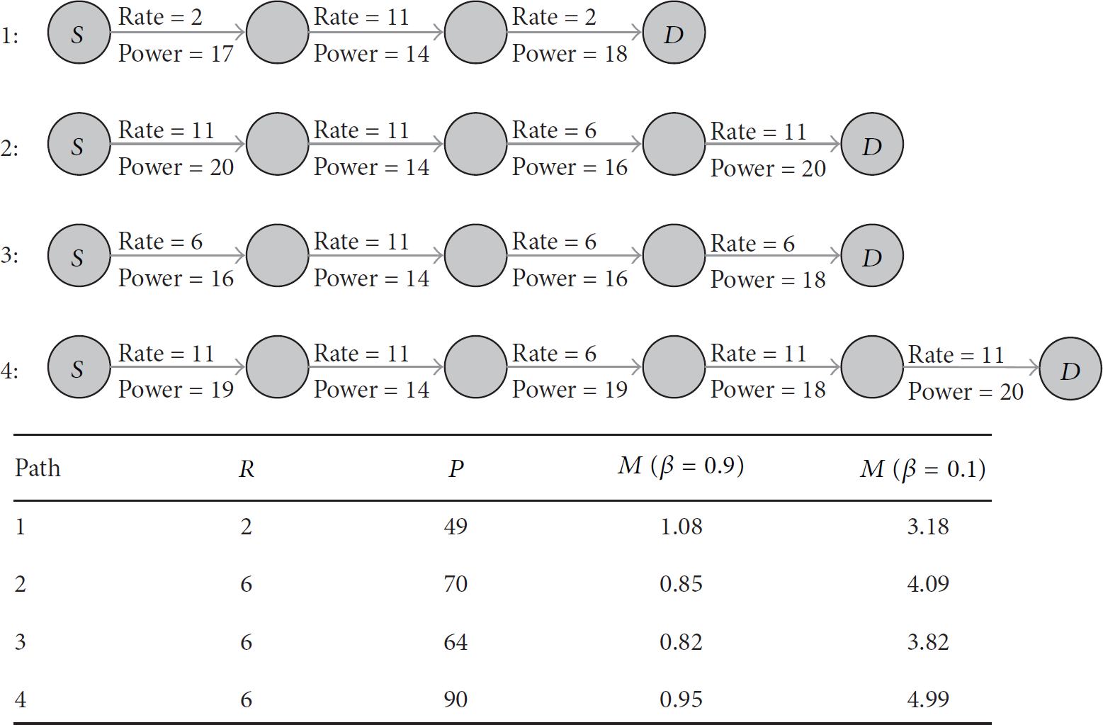
A-ODMRP examples.
The first path has the smallest P value. However, the first path has the smallest R value. The other paths have identical R values, but paths 2, 3, and 4 have different P values. Now consider path 4. This path has the largest P value because it has an extra hop. Thus, in this paper, the proposed metric that uses the sum of the transmission power levels considers energy consumption and indirectly reflects the hop-counts of the path.
Path 1 can facilitate communication between S and D with the lowest hop-count. However, the path has the smallest R value. Path 4 has the same R value as paths 2 and 3 but the largest P value as well as an extra hop. Paths 2 and 3 have identical R values, but path 2 requires greater power because it has more hops with rate = 11 in than path 3.
As shown in Figure 5, when β is 0.1, the transmission power level part has greater weight, and path 1 has the smallest metric. However, when β is 0.9, path 3 has the smallest metric. This is reflected in the fact that, for different values of β, either path can appear better.
4. Simulation
In this section, we study the performance of A-ODMRP and compare it to ODMRP. We implemented the details of A-ODMRP in Qualnet [17] and conducted a set of simulations.
4.1. Simulation Settings
The simulation settings are listed in Table 2. All numbers represent average values over 10 runs. The simulation of ODMRP used a fixed transmission power level (20 dBm) and a fixed transmission rate (11 Mbps) for the physical layer. In simulations of A-ODMRP, the transmission power level of the physical layer ranged from 10 dBm to 20 dBm and the transmission rate of the physical layer varied from 2 Mbps to 11 Mbps. The random waypoint mobility model was used in the simulations. The maximum mobility of the nodes was 2 m/s. In lower mobility environments, the maximum mobility of the nodes with multicast routing protocols was typically 2 m/s for simulations.
Simulation parameters.

4.2. The Impact of Beta
As explained in previous section, A-ODMRP consists of two parts: the minimum of the rates (R) of each hop in the routing path and the sum of the transmission power levels (P) of the physical layer in the route. Hence, P can indirectly reflect the hop counts of the route. The weight assigned to the first factor is denoted by β, whereas the weight assigned to the second factor is
To measure the impact of β on the performance of A-ODMRP, we simulated the experiment described in the previous section with
The results for
Average goodput and path length for beta.

To measure the impact of β on the performance of A-ODMRP, we simulated another experiment with

Comparison of average goodput of connections grouped by path length.
In Figure 6, when
4.3. Performance of A-ODMRP
Figures 7–13 show the performances of A-ODMRP in various scenarios for different numbers of multicast receivers and compare it to that of ODMRP. The number of multicast receivers varied from three to 18 in the simulation scenarios. To share a sufficient number of nodes belonging to the forwarding group, multicast group members were selected in the network.
Number of transmitted data packets per delivered data packet.

Size of the forwarding group.
Total goodput of the network.

Number of route management packets per delivered data packet.
Delay in discovering the route.

Constant versus variable number of multicast groups.

Energy consumption during transmission.
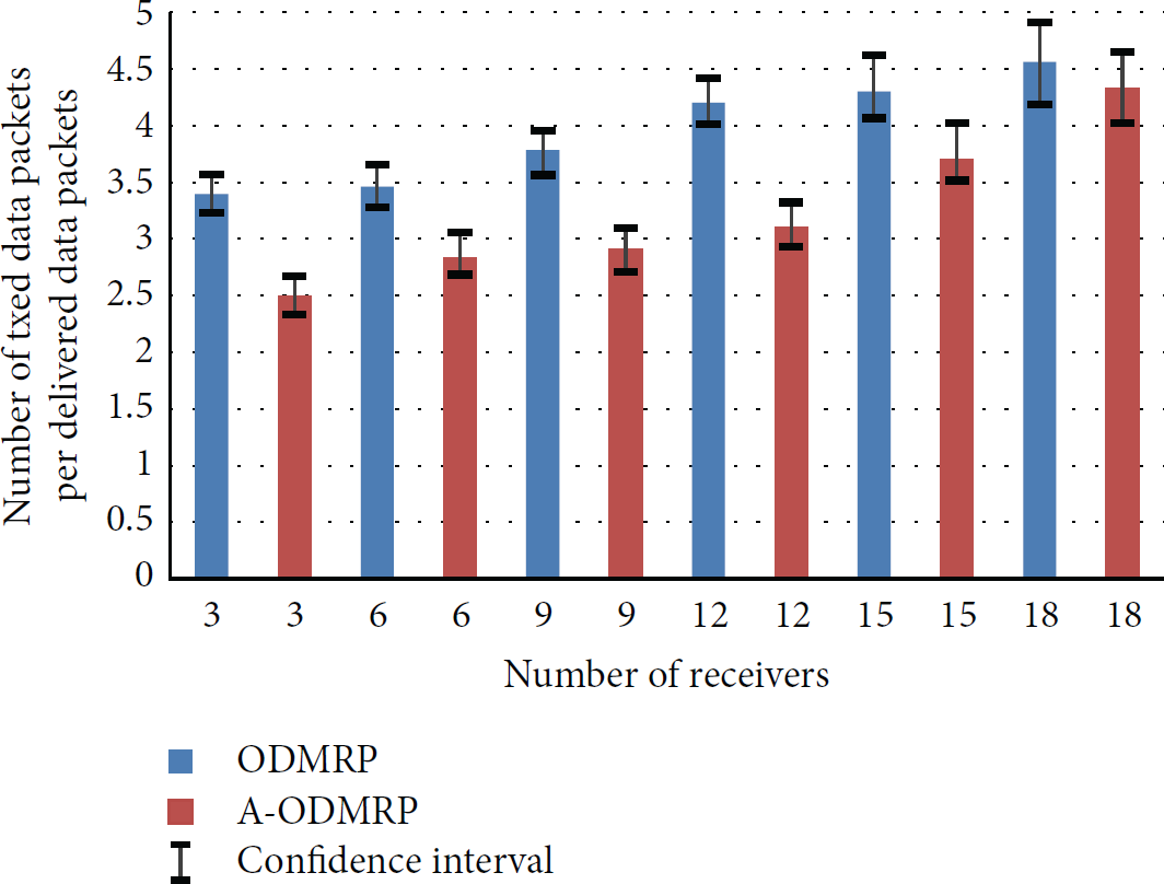
Figure 7 shows the number of transmitted data packets per delivered data packet as the number of multicast receivers increased. The number of delivered data packets was the sum of the delivered data packets for each receiver. The number of transmitted data packets was the sum of the transmitted data packets transmitted by each node in the network. The transmitted data packets included packets that were dropped or retransmitted by intermediate nodes. If the number of transmitted data packets per delivered data packet was closer to the maximum, there were many packets dropped or retransmitted by intermediate nodes.
As shown in Figure 7, the confidence intervals of A-ODMRP are a little smaller than ODMRP's. When the number of receivers was 15 or 18, the confidence intervals of both protocols are bigger than others. As the number of multicast receivers increased, the interference between the nodes increased and the gap between maximum and minimum increased in both protocols.
As indicated in Figure 7, A-ODMRP generally yielded smaller values than ODMRP. That is, A-ODMRP had a fewer number of dropped and retransmitted packets due to interference between the nodes belonging to the forwarding group. When the number of receivers was 9 or 12, A-ODMRP indicated a well-marked interval compared to ODMRP. When the number of receivers was 15 or 18, the difference between the two multicast routing protocols decreased. In Figure 8, as the number of multicast receivers and the size of the forwarding group increased, there was excessive interference between the nodes, and the number of dropped and retransmitted packets increased in both protocols.
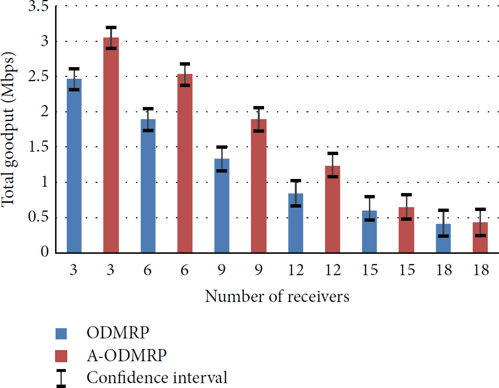
Figure 9 shows the goodput of both protocols as the number of multicast receivers increased. As shown in Figure 9, A-ODMRP generally recorded higher goodput than ODMRP. When the number of receivers was 9, A-ODMRP provided an improved goodput of up to 42%. However, when the number of receivers was 15 or 18, the gap of goodput between A-ODMRP and ODMRP decreased. As shown in Figure 7, as the number of multicast receivers increased, the interference between the nodes and the number of dropped and retransmitted packets increased in both protocols. As shown in Figure 9, the confidence intervals of goodput of A-ODMRP are a little smaller than ODMRP's. However, there is no big difference between A-ODMRP and ODMRP.
Figure 10 shows the number of route management packets per delivered data packet as the number of multicast receivers increased. The number of route management packets per delivered data packet was the routing overhead of the multicast routing protocols. As shown in Figure 10, A-ODMRP generally had lower routing overhead than ODMRP. When the number of receivers was 9 or 12, A-ODMRP indicated a well-marked interval compared to ODMRP.
A-ODMRP generated more route management packets and had a smaller routing overhead than ODMRP. This was because the number of delivered data packets in ODMRP was significantly smaller when the number of receivers was 9 or 12, as shown in Figure 9. However, when the number of receivers was 15 or 18, the gap in routing overhead between A-ODMRP and ODMRP decreased markedly. This was because, as shown in Figure 9, the gap in goodput between A-ODMRP and ODMRP was small.
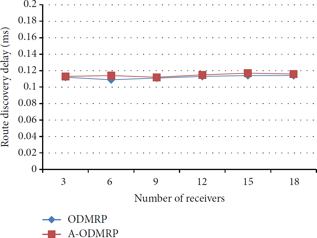
Figure 11 shows the delay in discovering the route between sources and receivers as the number of multicast receivers increased. As shown in Figure 10, the gap in the delay between the two protocols was very small. A-ODMRP and ODMRP have same route discovery procedure. A-ODMRP has just more data processing procedure such as comparing metric and updating Tx_Infor_Table compared to ODMRP. Data processing time is very small. Therefore, in A-ODMRP, the complexity of data processing procedure did not influence the route discovery delay.
As mentioned above, when the number of receivers was from three to 12, A-ODMRP provided an improved goodput of up to 42% compared to ODMRP. Moreover, A-ODMRP had a smaller routing overhead, despite the fact that A-ODMRP generated additional route management packets. However, when the number of receivers was 15 or 18, the gap in performance between the two protocols was significantly reduced. When the number of receivers was 12, the sum of the average number of forwarding group members and the average number of multicast group members was 28 for A-ODMRP and 35 for ODMRP. When the number of receivers was 15, the sum of the values was 36 for A-ODMRP and 39 for ODMRP. When the number of receivers was 18, the sum of the values was 41 for A-ODMRP and 43 for ODMRP. Therefore, when the sum of the average number of forwarding group members and the average number of multicast group members was 30 or less, the proposed multicast routing protocol exhibited its best performance. This was in a network environment consisting of 50 nodes that were uniformly placed in a 1200 m × 1200 m area.
Figure 12 shows a comparison between maintaining a constant number of multicast groups and a variable number of multicast groups as the number of multicast receivers increased from three to 18. In the simulation with a constant number of multicast groups, there was one group that had only one source and several receivers. In the simulation with a variable number of multicast groups, there were several groups that had multiple sources and receivers. As shown in Figure 12, there was no correlation between increasing the number of multicast groups and the goodput of A-ODMRP.
Figure 13 shows the energy consumption of each node. The distribution of active nodes in A-ODMRP was more concentrated than in ODMRP. Unlike ODMRP, which was not allowed to duplicate route management packets, when a node received a duplicated route management packet, a node under A-ODMRP compared the old packet against the new one. If the metric of the new packet was less than that of the old one, the node rebroadcasted the route management packet.
As shown in Figure 13, the energy consumption of A-ODMRP and ODMRP was 445.42 mJ and 479.25 mJ, respectively. A-ODMRP reduced energy consumption by 7% in the entire network compared to ODMRP. A-ODMRP has a control mechanism with a cross-layer algorithm for the physical layer. When a node transmits multicast data, A-ODMRP has an adaptive control mechanism for the physical layer and can adjust the transmission rate and power level of the physical layer. A-ODMRP can reduce unnecessary multicast data transmission and the energy consumption of the nodes belonging to the forwarding group.
5. Conclusions and Future Works
In this paper, we proposed A-ODMRP, an improved version of ODMRP. ODMRP does not allow a duplicated Join Query in the backward learning procedure, because of which finding the optimal path is rendered difficult. The nodes using ODMRP transmit multicast data at a fixed transmission rate and power level for the physical layer. As the number of nodes belonging to the forwarding group increases, there is serious interference between the nodes, wasting valuable resources, such as channel bandwidth.
However, A-ODMRP has an adaptive control mechanism with a cross-layer algorithm for the physical layer. When a node transmits multicast data, the node using A-ODMRP can adjust the transmission rate and the power level of the physical layer based on the SNR between the nodes. A-ODMRP prevents the use of excessive transmission power, reduces energy consumption during transmission, and minimizes packet drop or retransmission due to interference between nodes belonging to the forwarding group. When the percentage of active nodes forwarding group members and multicast group members was 60% or less in the network, simulation results confirmed that A-ODMRP provided an improved goodput of up to 42% and reduced energy consumption by 7% in the entire network compared to ODMRP.
Our proposed A-ODMRP is able to consider intraflow interference. However, A-OMDRP does not sufficiently consider interflow interference. In future work, we plan to study an algorithm to adjust a route dynamically to optimize the transmission rate and reduce interflow interference in mobile ad hoc networks.
Footnotes
Conflict of Interests
The authors declare that there is no conflict of interests regarding the publication of this paper.
Acknowledgment
This work was supported by the National Research Foundation of Korea (NRF) grant funded by the Korea government (MSIP) (NRF-2014R1A2A1A11053047).