
Abstract
In a wireless sensor network, sensor nodes are deployed in an ad hoc fashion and they deliver data packets using multihop transmission. However, transmission failures occur frequently in the multihop transmission over wireless media. Thus, a loss recovery mechanism is required to provide end-to-end reliability. In addition, because the sensor nodes are very small devices and have insufficient resources, energy-efficient data transmission is crucial for prolonging the lifetime of a wireless sensor network. This paper proposes a transmission power control mechanism for reliable data transmission, which satisfies communication reliability through recovery of lost packets. The proposed method calculates packet reception rate (PRR) of each hop to maintain end-to-end packet delivery rate (PDR), which is determined based on the desired communication reliability. Then, the transmission power is adjusted based on the PRR to reduce energy consumption. The proposed method was evaluated through extensive simulations, and the results show that it leads to more energy-efficient data transmission compared to existing methods.
1. Introduction
A wireless sensor network (WSN) consists of tiny nodes with sensing, computation, and wireless communication capabilities. WSNs can be used in a variety of applications, such as industrial, civilian, environment, home, health, and military, to collect and deliver information to a central location, called the sink node [1, 2]. In order to transmit data to the sink node, sensor nodes utilize multihop transmission over the wireless medium. Since the transmission condition for sensor nodes can change, the end-to-end communication reliability needs to be considered. In addition, energy-efficient data transmission needs to be taken into account since sensor nodes have limited battery capacity [3].
Several loss recovery mechanisms have been proposed to provide end-to-end reliability for multihop transmission in WSNs, such as Hop-By-Hop (HBH) and End-to-End (E2E) loss recovery schemes. These schemes basically differ in how retransmission of lost packets is performed. In HBH, a node requests for retransmissions of lost packets from its previous node on a route from the source to the sink node. In contrast, in E2E, nodes send requests to the source node for retransmissions of lost packets. These loss recovery mechanisms have benefits and drawbacks in terms of end-to-end delay and memory requirements. In E2E, the end-to-end delay increases as the number of hops increases. However, the intermediate nodes do not have to cache data packets requiring less memory in the network. In contrast, HBH reduces the end-to-end delay by caching data in every node over a routing path but requires more memory in the network. In order to overcome the limitations of the existing loss recovery mechanisms, the Active Caching (AC) scheme was proposed in our previous work [4]. The AC scheme results in different retransmission request points (i.e., caching nodes) based on the required communication reliability. However, bad channel conditions can lead to many retransmission points and thus increase the number of retransmissions. Furthermore, all three aforementioned loss recovery mechanisms do not consider energy consumption during data transmission. Energy-efficient communication is crucial for battery-driven sensor nodes. Therefore, an energy-efficient transmission power control that considers the end-to-end communication reliability is needed.
This paper proposes an energy-efficient transmission power control scheme that considers end-to-end communication reliability by analyzing the required transmission power between a sender and a receiver along a route from source to destination. The proposed method is applied to the AC scheme to dynamically adjust caching points based on the required communication reliability. In the proposed method, the communication reliability (CR) metric is defined in terms of the Packet Delivery Ratio (PDR) from a source to a destination. (The PDR is the ratio in which the number of packets that are successfully delivered to a destination is molecule and the number of packets that have been sent by the sender is denominator.) Thus, when a traffic requires a certain level of end-to-end reliability, its PDR for each hop should be greater than CR. Otherwise, the QoS for the traffic cannot be guaranteed. If PDR does not satisfy a given CR, the caching position for retransmitting lost packets is adjusted to guarantee the required PDR and thus CR. Then, the required transmission power level of the sender node is determined from the target Signal-to-Noise Ratio (SNR) between a sender and a receiver. The target SNR can be obtained from receiver sensitivity, which represents the minimum received power required at the receiver to satisfy a given target Bit Error Rate (BER). The target BER in turn can be obtained based on Packet Error Rate (PER) for each hop, and PER is determined based on the required PDR for each hop.
The required PDR for each hop determines its Packet Error Rate (PER), which in turn dictates BER. Then, the required BER leads to the target Signal-to-Noise Ratio (SNR). Finally, the target SNR determines the required transmission power level of the sender node.
The proposed transmission power control scheme leads to low energy consumption and at the same time maintains the required end-to-end CR. Our performance evaluation shows that adjusting transmission power based on PER improves energy efficiency.
The remainder of the paper is organized as follows. Section 2 discusses the related work on transmission power control methods for WSNs. The proposed transmission power control method is presented in Section 3. Section 4 presents the performance evaluation and Section 5 concludes the paper.
2. Related Work
The transmission power control can be distinguished as either a network-based approach or a per-node-based approach. The network-based approach determines a single transmission power for all neighboring links, whereas the per-node-based approach uses a different transmission power for each individual link [5]. Kubisch et al. and Panichpapiboon et al. proposed network-based approaches for maintaining network connectivity [6, 7]. However, the network-based approach cannot achieve low-power consumption during data transmission because transmission power requirements of individual neighboring links are not considered.
There are several schemes that utilize the per-node-based approach. Lin et al. proposed a transmission power control technique where every node broadcasts a group of beacons at different transmission power levels and constructs a linear function based on the Received Signal Strength Indication (RSSI) readings [5]. The sender then determines the transmission power level for a receiver based on the linear function. However, this method requires a lot of memory to determine the linear function. Correia et al. proposed two types of transmission power control schemes [8]. The first scheme adjusts transmission power level based on different control thresholds that are determined based on the number of acknowledged messages during transmission. However, determining the proper thresholds for real applications is difficult. The second scheme considers signal attenuation and background noise. The signal attenuation is the ratio of transmitted power at a sender and received power at a receiver. The predictive model for the background noise and the threshold of received power were obtained empirically using experiments. Then, the transmission power control is performed based on the predictive model. However, since the predictive model is based on empirical results, it cannot accurately predict the proper transmission power if the actual network condition is different from the experiment environment.
Zhao et al. calculated the minimum desired transmission power through a proportional expression [9], where the ratio of the maximum transmission power and the received power was the same as the ratio of the minimum transmission power and the received power threshold. The received power threshold depends on environmental conditions, but the authors did not provide any method to determine the threshold value. Sheu et al. proposed a two-step process to determine transmission power [10]. In the initial step, each sensor node broadcasts 100 probe packets per transmission power level. The sensor nodes then determine initial transmission powers based on acknowledgements for the probe packets. In the maintaining step, the transmission power is controlled using the average RSSI and the Link Quality Indication (LQI). The transmission power is then adjusted by comparing the upper and lower bounds of RSSI and the LQI threshold. The bound values and the threshold were obtained using experiments. Xiao et al. proposed a transmission power control scheme for Body Area Networks (BANs) [11]. Their method handles the transmission power control between a base station and sensor devices in a star topology. This is done by doubling the transmission power if the average RSSI is lower than the lower-bound threshold. In addition, if the average RSSI is higher than the upper-bound threshold, the transmission power is reduced by a constant amount. Both the upper- and lower-bound thresholds were obtained using experiments.
Existing transmission power control techniques either require many probe packets to find the proper transmission power or utilize threshold values based on empirical results. However, these probe packets lead to higher energy consumption and experimental results can vary according to environmental conditions. In addition, existing methods do not consider end-to-end communication reliability. For example, in the studies of Ferrari et al. [12, 13], the optimal transmission power was determined by the route BER at the end of a multihop route. The route BER was derived based on the link BER, and transmission power and route were selected for minimizing it. However, they ignored the end-to-end PDR which is important to guarantee end-to-end communication reliability. If transmission power is decreased without considering the end-to-end PDR, more retransmissions and larger memory will be required to guarantee communication reliability. In contrast, our proposed method considers end-to-end communication reliability by developing a wireless channel model and analyzing the required transmission power between a sender and a receiver.
3. The Proposed Transmission Power Control Mechanism
3.1. System Model
The proposed method adjusts transmission power to satisfy the required PERs of wireless links based on the end-to-end reliability of a multihop transmission. Figure 1 shows the system model of the proposed transmission power control mechanism. As mentioned in Section 1, CR means the expected PDR value from a source node to a sink node. When data packets are delivered, PDR value between the source node and the current node is (re)calculated and it is compared to the given CR at each node.

System model of the proposed method (CR is 90%).
In the system model, at first, the loss recovery schemes are applied to the proposed method for the purpose of retransmission for the lost packet. Although the proposed method is based on Active Caching, other schemes such as HBH or E2E also can be applied to the proposed method. Then, a sender estimates PDR from the next node to the sink node. If the estimated PDR at the maximum power does not guarantee CR, a sender reduces hops of end-to-end and reestimates PDR. From the estimated PDR, a sender determines transmission power. The estimation is performed through the information of the query message from the sink node. These procedures are repeated at every node over a routing path. When data caching occurs at the intermediate node, PDR value until the previous hop is compensated to 1 and PDR value of the current hop multiplies to the compensated value. Thus, the PDR value of the 3rd hop in Figure 1 becomes 0.95 when the packet loss rate is 0.05. If data packets are lost during transmission, retransmissions are requested to the data caching nodes. For data transmission, the routing paths can be selected with the shortest path and CSMA/CA as a medium access control can be used.
3.2. Transmission Power Control
Algorithm 1 represents the pseudocode of the proposed transmission power control algorithm. The first part of the algorithm (lines 4–7) calculates PDR of the current (i.e., hth) hop by taking the product of packet reception rates (PRRs) of all the hops from the source node to the current node h based on the following equation:

I: Piggybacked information in a query message (1) (2) (3) (4) (5) Apply Active Caching (6) Set the node h to a caching position (7) (8) Obtain (9) (10) (11) (12) (13) (14) (15) (16) Calculate transmission power using (17) Transmit data (18) (19) (20) (21) Recalculate (22) (23) Transmit data with maximum power (24) (25)
The second part of the algorithm (lines 8–25) determines the required transmission power using information contained in query messages from the sink node. The sink node periodically broadcasts query messages to (re)establish routing paths and deliver commands. In each sensor node, the hop-count from the sink node to this node and PDR for each hop are piggyback on the query message. Based on this information, the estimated PDR from the next node (i.e., node


The packet loss rate


Since the receiver sensitivity for PDR is determined based on
3.3. Active Caching
The proposed transmission power control method to improve energy consumption is based on the AC scheme, which supports various levels of CR for applications [4]. Therefore, this subsection briefly discusses the AC scheme for the sake of completeness. The interested reader is referred to [4] for a detailed discussion of the AC scheme.
Algorithm 2 shows the algorithm for the AC scheme, where
(1) (2) (3) (4) (5) (6) (7) cache data packets at node (8)
3.4. Determination of Transmission Power
In a wireless system, the received power (


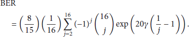
PRR depends on PER, which is a function of BER and frame size, and is defined by

Target BER and required SNR according to PRR.


BER result for IEEE 802.15.4 in the 2.4 GHz frequency band.
The path loss as a function of distance, 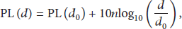
The path loss model in IEEE Std. 802.15.4 specifies a two-segment function and is given by the following equation:


The noise power, 

After substituting the calculated γ and 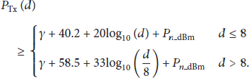
4. Evaluation
This section discusses the performance evaluation of the proposed transmission power control method. This is done by first analyzing the transmission power and then the proposed method is compared with the existing methods Hop-By-Hop (HBH) loss recovery, End-to-End (E2E) loss recovery, and Active Caching (AC) by simulation. The simulation environment is based on the IEEE 802.15.4 standard with data rate of 250 kbps operating at 2.4 GHz frequency with 2 MHz bandwidth. A frame size is 50 bytes. In addition, the CC2420 chip for WSN is used as the RF transceiver.
4.1. Analytical Analysis of Transmission Power
This subsection analyzes the transmission power at the sender and the reception power at the receiver in a single hop based on the path loss model of the IEEE 802.15.4 standard and interference is not considered. Adjusting transmission power according to PRR is compared with using maximum transmission power. For the analysis, PRR values are 99.9%, 99%, and 95%, and the distance between the sender and the receiver varies from 1 m to 60 m.
Figure 3 shows the minimum transmission power required to guarantee a given PRR as a function of distance. When the distance between the sender and the receiver is less than 45 m, energy can be saved using transmission power control. In addition, since the maximum transmission power is 0 dBm for the RF transceiver, a given PRR cannot be satisfied when the required transmission power is over 0 dBm.

Minimum transmission power of a sender.
Figure 4 shows the received power as a function of distance. When the sender uses the maximum transmission power, the reception power at the receiver decreases due to path loss as was discussed in Section 3.4. The proposed method maintains the receiver sensitivity by considering the required PRR. When the maximum transmission power is used, the energy difference between the reception power and the receiver sensitivity will be wasted. On the other hand, successful transmission for a given PRR cannot be guaranteed if the reception power is lower than the receiver sensitivity.
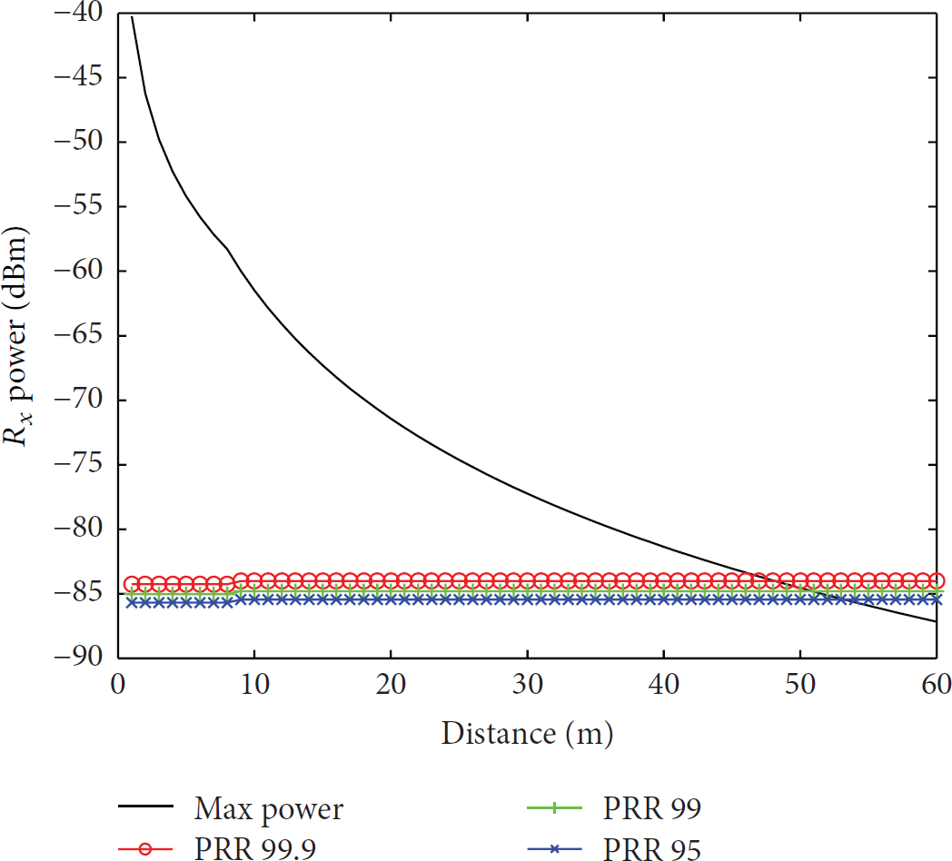
Received power at a receiver.
Figure 5 shows the transmission power as a function of distance of a sensor node using the proposed transmission power control mechanism. When the distance between the sender and the receiver increases, the transmission power has to also increase in order to maintain the receiver sensitivity required to satisfy a given PRR. As can be seen from the figure, the transmission power is different for different PRR values. When PRR is high, higher transmission power is needed to increase the probability of successful data transmission.

Minimum transmission power at a CC2420 RF module of a sender.
Figure 6 shows the reception power as a function of distance when the proposed transmission power control is employed. When the reception power is lower than the receiver sensitivity, the transmission power is increased. The receiver sensitivity varies according to the given PRR, and thus the reception power will also be different for different PRR values. In addition, because the maximum transmission power is 0 dBm, the received power can be lower than the receiver sensitivity if the distance between two communicating nodes is longer than the transmission range. In this case, the target BER and PRR cannot be guaranteed.

Received power at a CC2420 RF module of a receiver.
4.2. Simulation Study
The simulator was implemented using the SMPL library [23], which is an event-driven simulation library using C-language. In our simulation, a varying number of nodes (70–200) are randomly deployed in a 200 m × 200 m field. Each node has 10 Joules as the initial energy. The communication reliability (CR) is 0.95. When a transmission fails, there are two additional opportunities to retransmit the lost packet. The path loss model
The CC2420 chip provides eight transmission power levels [14] as shown in Table 2. Therefore, the transmission power of the sensor nodes is chosen from these transmission power levels. This is done by applying supremum (the supremum (sup) of a subset S of a totally or partially ordered set T is the least element of T, i.e., greater than or equal to all elements of S) of the estimated transmission power in (15) to the available transmission power levels of the RF transceiver as defined in the following:
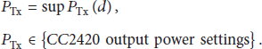
Output power levels in CC2420 [14].

The proposed transmission power control scheme, referred to as AC_TPC, is compared with the typical transmission power control and existing loss recovery methods. The typical transmission power control method, referred to as AC_Typical, adjusts transmission power by considering only the next hop and applied to the AC loss recovery scheme. It calculates transmission power using receiver sensitivity of the next node without considering multihop transmission. The existing loss recovery methods consist of HBH and E2E, and they do not employ transmission power control.
Figure 7 shows the number of times data is cached for all the methods. The E2E scheme does not cache data packets at intermediate nodes of a routing path, but all other methods require caching to recover lost packets. The HBH scheme has the highest memory requirement because it stores data packets at every node, while the AC scheme requires less number of caching nodes because data packets are cached based on CR. Since both AC_TPC and AC_Typical rely on the AC loss recovery mechanism, they have less memory requirements than HBH. However, because both AC_TPC and AC_Typical apply transmission power control, their PDR may be different from AC. The reason why there is a difference among AC, AC_TPC, and AC_Typical is that they have different PDR values during data transmission. In general, AC_Typical requires more caching nodes.

Number of times data is cached.
Figure 8 shows the total number of retransmissions. The HBH scheme has the lowest number of retransmissions because retransmission requests are made only to the previous node in a routing path. In contrast, the E2E scheme has the highest number of retransmissions because retransmission requests are made to the source node. The retransmission count of AC is somewhere between HBH and E2E. Among AC, AC_TPC, and AC_Typical, AC_Typical generates the largest number of retransmissions. AC_TPC adjusts transmission power by taking into account the end-to-end reliability, while AC_Typical adjusts transmission power only for the next hop. Thus, the PDR value for AC_Typical is lower than that of AC_TPC. For this reason, its retransmission count as well as the number of times data is cached is greater than AC_TPC as shown in Figures 8 and 7, respectively.

Number of retransmissions.
Table 3 shows the number of received packets at the sink node. When the number of received packets is compared to the number of generated packets, all methods guarantee the given CR of 95%. To accomplish this, HBH requires more caching points and E2E causes more retransmissions. AC requires less caching points than HBH and less retransmissions than E2E. Even though the transmission power control methods AC_Typical and AC_TPC cause more data caching points and retransmissions than AC, they satisfy the required CR and reduce energy consumption during data transmission.
Total number of received packets received at the sink node.

Figure 9 shows the total energy consumed. The HBH scheme, which does not use transmission power control, shows the least amount of energy consumption because it has the lowest retransmission count among the five methods. When the transmission power control is applied, the amount of energy consumption can be reduced as HBH. Even though transmission power control causes more retransmissions, it results in less energy consumption. These results clearly show that the proposed transmission power control achieves energy efficiency in WSNs. A typical transmission power control scheme, such as AC_Typical, does not satisfy efficient reliable data transmission in terms of memory requirements and retransmissions even though it provides energy savings. However, the proposed method, AC_TPC, transmits data packets to the sink node with less retransmissions even though it has similar energy requirement as AC_Typical. Furthermore, it requires less memory than AC_Typical. Therefore, the proposed method improves energy efficiency during reliable data transmission with guaranteed CR.

Total energy consumption (mJ).
5. Conclusion
This paper proposed a transmission power control mechanism for reliable data transmission, which satisfies given communication reliability through recovery of lost packets. The proposed transmission power control method adjusts the transmission power by considering the end-to-end PDR determined based on the desired communication reliability. Although the proposed method consumes slightly more energy than the typical transmission power control method, it saves more energy than other loss recovery techniques without transmission power control. Moreover, the proposed method shows superior performance over the existing methods in terms of memory requirements and number of retransmissions.
Footnotes
Conflict of Interests
The authors declare that there is no conflict of interests regarding the publication of this paper.
Acknowledgment
This research was supported by Basic Science Research Program through National Research Foundation of Korea (NRF) funded by the Ministry of Education (NRF-2013R1A1A2059741).