We design a scheme of precoding matrices for two-way multiuser relay systems, where a multiantenna relay station (RS) operating in an amplify-and-forward model simultaneously receives information from all multiple-antenna users. Considering the feasibility in mathematical analysis, users are distributed in two symmetrical groups. To reduce the complexity of proposed precoding scheme, we employ the QR decomposition and complex lattice reduction (CLR) transform to replace the two times singular value decomposition (SVD) of conventional BD-based precoding algorithm by introducing a combined channel inversion to eliminate the multiple users interference (MUI). Simulation and performance analysis demonstrate that the proposed LR-MMSE algorithm has not only a better bit error rate (BER) performance, a higher sum-rate, and simple architecture, but also 89.8% and 35.5% less complexity compared to BD- and MMSE-based scheme.
1. Introduction
Two-way relaying (TWR) cooperation has attracted considerable attention due to the high spectral efficiency. A typical model of the TWR protocol with multiple access channel (MAC) phase and broadcast channel (BC) phase has been investigated in [1]. In the MAC phase, two source nodes transmit their message to the relay node simultaneously. After processing the mixed received signal at the relay, a combined version of the received signal is broadcast to each source node in the BC phase.
Among the numerous two-way relaying protocols, such as amplify-and-forward (AF) and decode-and forward [2], AF protocol gets favored as one or more low-complexity relay nodes are adopted to assist the communication between sources and destinations without decoding the signals.
In wireless sensor networks (WSNs), a large number of static or mobile sensors cooperate to perceive, compute, and transmit message assistant by the relay [3]. Since sensor nodes are usually operated by lightweight batteries that are difficult to replace or recharge, energy becomes one of the most crucial resources in WSNs. Moreover, experimental measurements have shown that the energy consumption of a sensor node is dominated by communications [4]. Thus, a simple and low-complexity transceiver model for sensors is a powerful solution to solve this problem. Recently, a prominent research in [5] has proposed a multilevel physical layer network coding to rule the rate of sensors, which saves the power of networks potentially.
As we known, multiple-input multiple-output (MIMO) relays potentially obtain both spectral efficiency and link reliability by exploiting the multiple antennas, and, jointing the TWR technology, it can improve the system performance dramatically. Recently, the precoding design for TWR MIMO systems is extended to multiuser cases, which can be roughly divided into two categories: symmetric systems and asymmetric systems [6–11]. In symmetric system, all users are supposed to be distributed in two groups in the form of pairings [6–8]. In asymmetric systems, a based station exchanges messages with multiple users [9–11], which is a typical scenario of cellular networks.
Unlike the received signals in single-user MIMO (SU-MIMO) systems, the received signals of different users in multiuser MIMO (MU-MIMO) systems not only suffer from the noise and intra-antenna interference but are also disturbed by the multiuser interference (MUI). However, when we consider two-way relaying multiuser MIMO (TWR MU-MIMO) systems, the MUI becomes more complicated, since there are two groups of users mixing in the received signals.
Channel inversion strategies based on zero forcing (ZF) and minimum mean squared error (MMSE) can be used to cancel the MUI but result in amplifying the noise [12, 13]. Block diagonalization (BD) has been proposed in [14, 15] to improve the system throughput and provide convenience for the power control. Literature [16] studies the precoding scheme of the singular value decomposition (SVD) and employs a technology of channels aligning referring to [17]. However, the complexity of SVD is very high when the number of users and the specification of the antenna are large. In order to reduce the complexity, generalized singular value decomposition (GSVD) has been applied in [18] to design the downlink of MIMO systems. Unfortunately, there is also a great performance loss at low signal to noise ratios (SNRs) when the noise is the dominant factor. In recent research, a systematic scheme is proposed in [7], which imposes a power constraint at the relay node and obtains an approximate result by fixing the transmitting and receiving matrices at the user nodes firstly. In [19], a low complexity precoding algorithm is proposed to reduce the condition number of the effective number by introducing a complex lattice reduction (CLR) transform in one-way relay MU-MIMO systems.
In this paper, we focus on AF TWR MU-MIMO systems and strive to find a lower complexity and better performance precoding scheme. By employing a combined channel inversion and replacing the SVD with QR decomposition, we can cancel the MUI remarkably. Then, the CLR transform is used to design the precoding matrices of users which locate in another group and is in pairs of receiving users.
The rest of the paper is organized as follows. Section 2 describes the conventional system model. Section 3 introduces the BD-based precoding algorithm. The scheme LR-MMSE is proposed in Section 4. Performance analysis and simulation are given in Sections 5 and 6. Finally, we conclude this work in Section 7.
Notation. Throughout this paper, for a matrix A, , , , , and denote the trace, transpose, complex conjugate transpose, inverse, and pseudoinverse, respectively. “E” stands for the expectation of a random variable; the terms represent the -dimensional space with complex-valued elements. The notations and denote Frobenius-norm and 2-norm of matrix A. is a m-by-n identity matrix; is a m-dimensional zero matrix.
2. General System Model
Investigate an uncoded TWR MU-MIMO system, with K pairs of user equipment (UE) and one two-way relay station (RS) which operates in AF protocol. For simplicity, we consider a symmetric model in which users are divided into two groups: . The kth user in group l and the relay has equipped and antennas, respectively. A block diagram of such a system is shown in Figure 1.
System model.
Ruled that there is no direct link between two users and all the channels experience independent and flat MIMO fading. Let denote the data symbol at time t for the kth user in group l (). The performs transmit precoding beamforming with vector and transmits the signal in the following form of matrix:
where and satisfies . We assume the average power of the transmit signal is 1.
Then, users and exchange their signals by the assisted relay node RS in two phases. Firstly, in the multiple access channel (MAC) phase, and transmit their signals simultaneously to relay and the received signals at RS are given by
where is the channel coefficient coming from to RS and is a zero-mean addictive white Gaussian noise (AWGN) at the relay and .
In the broadcast (the broadcast channel) phase, the RS forwards and broadcasts the mixed signals to all user by multiplying a forward matrix , where
It is worth noting that the f is an assistant precoding matrix for decoding the signals at receiver sites. Since it is supposed that channel reciprocity (This assumption is reasonable when we consider time division duplex (TDD) systems. Channels in uplink and downlink are static and identical in the frequency domain.) is met within two phases, the received signals at the user side are
where is also a zero-mean AWGN at the and . The combines its own received signal (4) by using a received decoding vector to get the estimate
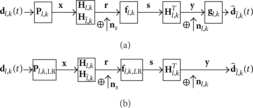
where denotes the information coming from , the subscripts l and , and represents the user pairings. For notational convenience, the time index t is henceforth wiped off. Refer to Figure 2(a), which shows the overall procedure for transmit- and receive-beamforming and relaying of multiuser two-way systems. Next, designs of the scheme of precoding matrices are given with the criteria of BD, ZF, and MMSE. Further, the lattice reduction is applied to suppress the bit error rate (BER) of the system. As a result, we can omit the decoding matrix to obtain a simple structure.
(a) The transfer model for conventional precoding algorithms. (b) The transfer model for the proposed LR-MMSE algorithm.
3. Generalized Design of BD-Based Precoding Algorithm
The BD- and SVD-based precoding algorithms are proposed in [10] and [12], respectively. Combining the two ideas, the BD-based scheme can be given as follows.
The received signals at the users and sides can be written as
The detail components of are
The 1st item can be dismissed by the perfect self-interference suppression, and the key in the rest of processing is to eliminate MUI and obtain a good performance of the signal estimation.
Based on the system model, the combined channel matrix is given by , where N denotes the sum of users’ antennas. We define so that , where . In order to eliminate the MUI in (7), we impose the BD constraint in which
Firstly, by employing the SVD to ,
where and are unitary matrices. The diagonal matrix is composed of the singular values of . Factorizing into two parts, consists of the first none-zero singular column vectors and holds the last zero singular column vectors, where is . Thus, lies in the null space of . The relay forward matrix can be obtained as
Substituting (10) into (7), we have the effective channel
Then, the second SVD operation is used to obtain the precoding and decoding matrix. We have
Finally, the user 's precoding matrix and the decoding matrix is obtained as , where is a diagonal matrix and its elements stand for the transmit power allocation. To guarantee that the is not a null matrix, we must have . Note that we omit the dimension matching matrices in (11) which will be mentioned in the next section.
4. The Proposed LR-MMSE Precoding Algorithms
In this section, we describe the proposed precoding algorithms based on a strategy that employs a combined channel inversion method, QR decompositions, and lattice reductions in detail. We can solve the questions with ZF and MMSE criteria. For a better BER performance, the complex lattice reduction is proposed to improve the MMSE performance.
4.1. ZF-Based Design
The ZF-based design of precoding matrix termed as ZF can be performed in two steps.
Step 1.
It is to obtain the relay forward matrix which eliminates the MUI completely by a QR decomposition of .
Firstly, by using the ZF inversion to the combined channel matrix H, we have
where is the pseudoinverse of matrix and is the submatrix of . Note that [12]. Thus, the off-diagonal block matrices of are zero and is in the null space of ; that is,
Imposing the QR decomposition on , we have
where is an orthogonal matrix. Then, substituting into (7), the 2nd and 3rd items will be equal to zeros.
Step 2.
It is to obtain the user precoding and receive decoding matrices and by a SVD of the effective channel.
Note that the degree of freedom between and is , we match the dimensions with the help of , and . Then, substituting and into the 4th item of , we have the effective channel
where . The ZF algorithm can be completed by applying the SVD operation to the matrix . Then, the user precoding and receive decoding matrices and are designed by and , respectively. ( denotes the precoding processing at the site of and denotes the receiving processing at the site of . This type of subscript contributes to distinguishing the two matrices.) Finally, we get the systematic ZF precoding scheme for users.
4.2. MMSE-Based Design
Similar to Section 4.1, the MMSE-based design of precoding matrix termed as MMSE is performed by introducing the MMSE inversion to the combined channel matrix; we have
where is the submatrix of pseudoinverse matrix and . Note that the regularization factor α approaches zero when the SNR is high, and thus we have [12]. This means that those off-diagonal block matrices of converge to zeros with the increase in SNR. Hence, the matrix is approximately in the null space of ; that is,
Through the QR decomposition of , where is also an orthogonal matrix and is an upper triangular matrix, we have
Since is invertible, we have
So the relay forward matrix for is designed as
By the above process and matching matrix , the received signals can be rewritten as
Then, the MMSE-BD algorithm also can be completed by applying the SVD operation to the effective channel matrix
The user precoding and receive decoding beamforming matrices of MMSE are obtained as
Finally, the systematic MMSE precoding schemes for all users are followed as
Operate similar circulation to obtain andthen Compute overall precoding scheme
,
)
4.3. LR-MMSE-Based Design
In this subsection, LR is applied to reduce the dimension of the effective channel which replaces SVD in MMSE algorithm. For convenience, we term it as LR-MMSE (see Figure 2(b)). A powerful and famous reduction criterion for arbitrary lattice dimensions was introduced by Lenstra et al. in [20], and the algorithm they proposed is known as the LLL (or ) algorithm [21, 22]. In order to reduce the complexity, a complex LLL (CLLL) algorithm was in [23], which reduces the overall complexity of the LLL algorithm by nearly half without sacrificing any performance. Through reducing the size of channels, CLLL can obtain better BER performance. In this paper, we employ the CLLL algorithm to implement the LR transform.
After the first MMSE precoding, we transform the MU-MIMO channel into parallel or approximately parallel SU-MIMO channels and the effective channel matrix for the is
We perform the LR transformation on in the precoding scenario [24]; that is,
where is a unimodular matrix with and all elements of are complex integers. The unimodular feature of guarantees that the energy will not change through the LR transform.
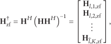
The MMSE precoding is actually equivalent to the ZF precoding with respect to an extended system model [25]. The extended channel matrix for the MMSE precoding scheme is defined as
By introducing the MMSE method, a trade-off between the level of MUI and the noise is introduced (see also [12]). Then, the LR-M-D precoding filter is designed as
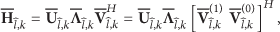
where and the multiplication by η will not result in transmit power amplifying since . From the mathematical expression in (15), the rows of H determine the effective transmit power amplification of the MMSE precoding. Correspondingly, the LR transformation for the MMSE precoding can be applied to the transpose of the extended channel matrix , and the LR transformed channel matrix is obtained as
where is the unimodular matrix for . Then, the LR-MMSE relay forwarding filter is given by
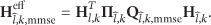
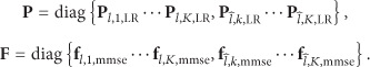
where the matrix and is the dimension of . Since LR transformation can reduce the matrix dimension, there should be . Finally, the systematic MMSE precoding scheme for all users is followed as
Since the lattice reduced precoding matrix P has near orthogonal columns, the required transmit power will be reduced compared to the MMSE precoding algorithms. Thus, a better BER performance than that of the BD precoding algorithms can be achieved by the proposed LR-MMSE precoding algorithm. The left work for receiver is to quantize the signals to the nearest vectors. The LR-MMSE algorithm is summarized in Algorithm 2.
Algorithm 2: The LR-MMSE precoding algorithm.
Steps and their operations
Applying the MMSE Channel Inversion
for k = 1 : K
end
Operate similar circulation to obtain and then Compute overall precoding scheme
5. Simulation and Performance Analysis
In this section, we analyze the proposed LR-MMSE algorithm in terms of computational complexity, architecture, BER, and achievable rates.
5.1. Computational Complexity Analysis
In this section, we measure the computational complexity of the precoding algorithms we have introduced by the total number of floating point operations Per Second (FLOPS). Note that the LR algorithm has complex variable, and the average complexity of CLLL algorithm has been given in [26] by FLOPS. The number of FLOPS for the complex QR decomposition and the real SVD operation are given in [27]. Moreover, the FLOPS number in a complex SVD operation is equivalent to its extended real matrix. The total FLOPS number required by the matrix operations is summarized below:
multiplication of and complex matrices: ;
QR decomposition of a complex matrix: ;
SVD of a complex matrix by only obtaining Λ and V: ;
SVD of a complex matrix by obtaining U and Λ and V: ;
inversion of a real matrix by Gauss-Jordan elimination: ;
inversion of a complex matrix by Gauss-Jordan elimination: .
The FLOPS of three types of precoding schemes are shown in Tables 1, 2, and 3, respectively. We assume the system is composed of 6 users () equipped 2 antennas and one relay station equipped 12 antennas. From Table 1, apparently, we know that the complexity of SVD is very large, resulting in the BD's complexity reaching a level of million. On the contrary, the combined channel inversion needs only 22805.4 FLOPS which operates in merely one time. Meanwhile, the LR-MMSE can save 35% of FLOPS of MMSE, while MMSE has saved 89.8% of FLOPS of BD.
Computational complexity of BD in case (6, 2, 12).
Steps
Operations
FLOPS
Number
1880064
Obtain
22560
SVD on
114432 Total 2017056
Computational complexity of MMSE in case (6, 2, 12).
Steps
Operations
FLOPS
Number
22805.4
46592.64
Obtain
22560
SVD on
114432 Total 206389
Computational complexity of LR-MMSE in case (6, 2, 12).
Steps
Operations
FLOPS
Number
22805.4
46592.64
Obtain
22560
CLLL transform
38387.97
544 Total 133169.5
Next, we fix the antennas of users and reveal the low complexity of LR-MMSE's property by enlarging the number of users. Ruling , we can obtain the performance comparison in Figure 3.
Computational complexity versus K by fixing each user's antennas.
Figure 3 shows that the complexity of BD-type precoding scheme grows rapidly with the increase in k, while it grows gently with respect to MMSE and LR-MMSE. This phenomenon is due to the significant influence of dimensions with regards to SVD. Note that the QR decomposition also needs to be implemented in K times, though there is only one time of the combined channel inversion. But, the QR decomposition is simpler than SVD.
5.2. Performance Analysis in Architecture
Compared to the BD and MMSE scheme, the LR-MMSE has a simple architecture. At the site of each user, the decoding matrix can be omitted, since the precoding processing in formula (31) has directly decoded the effective channel. This outperformance can contribute to saving a significant power of mobile users, even the relay stations. Moreover, it is worth noting that we need not employ the self-interference eliminating technology, due to the combined channel inversion having included the channel information of the receiver.
5.3. BER Performance Analysis
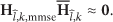
Recall that, with the increase in SNR, we have
in the LR-MMSE algorithm. Thus, the MU-MIMO channel is approximately decoupled into equivalent SU-MIMO channel. In most schemes of considering the channel noise, RBD is a common method. A result is shown in [28], which is like formula (33), which is not converged to zeros. Comparing the above two characters, LR-MMSE has more accurate receiving.
As we known, the condition number is a measurement of receiving error bits. In virtue of the defined condition number in [23],
the channel matrix can be detected with respect to orthogonality. Taking an example in a system of linear equations,
There are three cases for different kinds of matrices:
when the channel matrix is an orthogonal matrix, the condition number is 1; x will change a little with tiny changing b;
when it is a singular matrix, the condition number is ∞; x will change significantly with tiny changing b; even b has not changed;
when it is a nonsingular but not orthogonal matrix, the condition number will be large, and x changes between the above two cases.
As can be seen in Figure 4, the LR-MMSE has a smaller average of the effective channel compared to MMSE and BD. Thus, a significant power reduction and better BER performance are obtained.
The statistics of 1000 6∗6 channel matrices.
5.4. Achievable Sum-Rate Analysis
We have mentioned that LR-MMSE is similar to the LR-ZF. Thus, the received signal can be rewritten as
where is a detecting scalar and . Ordering , we have the normalization factor
For a unitary matrix, the norm satisfies
Thus, we have
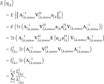
where is the transferring power of ith stream of and is the ith singular of . Naturally, the SNR with respect to the ith stream is given by
Thus, the 's achievable sum-rate is obtained as
Note that decreases with and converges to a maximum with .
6. Simulation Results
Considering a specification of antenna with , , and , six users are divided into two symmetrical groups. The perfect channel scenario is applied in which and all channels’ elements are fetched from the complex Gaussian process. For highlighting the performance of the proposed algorithm, we allocate the transmit power equally to each user.
Figure 5 shows that the LR-MMSE algorithm has the best sum-rate performance when MMSE and BD have a similar achievable sum-rate. In particular, when the SNR is 30 dB, the proposed algorithm has a 3.208 bit/s/Hz gain compared to the BD algorithm. Since the low SNR will affect the diagonality after the precoding processing in MMSE scheme, there is an inevitable performance loss. However, by virtue of the size reduction of CLLL transform, the LR-MMSE has obtained a performance compensation.
The achievable sum-rate versus SNR.
Additionally, in the process of simulating, we discover that choosing the optimal matching matrix Π can achieve nearly 1 bit/s/Hz gain. In this work, we did not study the optimization of power and matching matrices.
7. Conclusion
In this work, we have proposed a low complexity precoding scheme of two-way MU-MIMO relay systems with QR decomposition and complex LLL transform instead of two times SVD. For simplicity, users are distributed in two symmetrical groups. The performance analysis show that the LR-MMSE algorithm has not only a low complexity, but also a better BER, a simple structure at the site of the receiving user, and a theoretical maximum. Finally, a higher achievable sum-rate of the system is confirmed by simulation.
Footnotes
Conflict of Interests
The authors declare that there is no conflict of interests regarding the publication of this paper.
Acknowledgments
This work was partly supported by the National Natural Science Foundation of China (61340025, 61461029), the Natural Science Foundation of Jiangxi Province (20114ACE00200, 20142BAB217005, and 20142BBE50046), Technology Foundation of Department of Education in Jiangxi Province (no. GJJ13062), and China Postdoctoral Science Foundation Funded Project (nos. 2013MT541875, 2014MT561879).
References
1.
RankovB.WittnebenA.Spectral efficient protocols for half-duplex fading relay channelsIEEE Journal on Selected Areas in Communications200725237938910.1109/JSAC.2007.0702132-s2.0-33847736358
2.
ChenZ.LiuH.Spectrum-efficient coded modulation design for two-way relay channelsIEEE Journal on Selected Areas in Communications201432225126310.1109/JSAC.2014.1412062-s2.0-84895057582
3.
MisraS.ReissleinM.XueG.A survey of multimedia streaming in wireless sensor networksIEEE Communications Surveys and Tutorials2008104183910.1109/SURV.2008.0804042-s2.0-55849125003
4.
AnastasiG.ContiM.Di FrancescoM.PassarellaA.Energy conservation in wireless sensor networks: a surveyAd Hoc Networks20097353756810.1016/j.adhoc.2008.06.0032-s2.0-56449087483
5.
ChenZ.XiaB.HuZ.LiuH.Design and analysis of multi-level physical-layer network coding for Gaussian two-way relay channelsIEEE Transactions on Wireless Communications20146261803181710.1109/TCOMM.2014.2318052
6.
ChenM.YenerA.Multiuser two-way relaying: detection and interference management strategiesIEEE Transactions on Wireless Communications200988429643052-s2.0-7314908530610.1109/TWC.2009.081165
7.
JoungJ.SayedA. H.Multiuser two-way amplify-and-forward relay processing and power control methods for beamforming systemsIEEE Transactions on Signal Processing2010583, part 21833184610.1109/TSP.2009.2038668MR27580422-s2.0-77954724052
8.
ChenM.YenerA.Power allocation for F/TDMA multiuser two-way relay networksIEEE Transactions on Wireless Communications20109254655110.1109/TWC.2010.02.0903362-s2.0-76949097504
9.
EsliC.WittnebenA.Multiuser MIMO two-way relaying for cellular communicationsProceedings of the IEEE 19th International Symposium on Personal, Indoor and Mobile Radio Communications (PIMRC '08)September 2008Cannes, FranceIEEE1610.1109/PIMRC.2008.46997882-s2.0-69949151492
10.
YangH. J.JungB. C.ChunJ.Zero-forcing-based two-phase relaying with multiple mobile stationsProceedings of the 42nd Asilomar Conference on Signals, Systems and Computers (ASILOMAR '08)October 2008Pacific Grove, Calif, USA35135510.1109/ACSSC.2008.50744232-s2.0-70349662075
11.
DingZ.KrikidisI.ThompsonJ.LeungK. K.Physical layer network coding and precoding for the two-way relay channel in cellular systemsIEEE Transactions on Signal Processing201159269671210.1109/TSP.2010.2081985MR28154112-s2.0-78651354946
12.
JohamM.UtschickW.NossekJ. A.Linear transmit processing in MIMO communications systemsIEEE Transactions on Signal Processing20055382700271210.1109/TSP.2005.850331MR2170649
13.
CaiY.LamareR. C. D.FaR.Switched interleaving techniques with limited feedback for interference mitigationin DS-CDMA systemsIEEE Transactions on Communications20115971946195610.1109/TCOMM.2011.051711.090120A2-s2.0-79960556899
14.
SpencerQ. H.SwindlehurstA. L.HaardtM.Zero-forcing methods for downlink spatial multiplexing in multiuser MIMO channelsIEEE Transactions on Signal Processing20045224614712-s2.0-074232128010.1109/TSP.2003.821107MR2049894
15.
ChoiL.-U.MurchR. D.A transmit processing technique for multiuser MIMO systems using a decomposition approachIEEE Transactions on Wireless Communications20043120242-s2.0-234251026510.1109/TWC.2003.821148
16.
LeowC. Y.DingZ.LeungK. K.Joint beamforming and power management for nonregenerative MIMO two-way relaying channelsIEEE Transactions on Vehicular Technology20116094374438310.1109/TVT.2011.21720092-s2.0-83655191358
17.
StrangeG.Linear Algebra and Its Applications19983rdNew York, NY, USAThomson Learn
18.
SenaratneD.TellamburaC.GSVD beamforming for two-user MIMO downlink channelIEEE Transactions on Vehicular Technology20136262596260610.1109/TVT.2013.22410912-s2.0-84880523559
19.
ZuK.de LamareR. C.HaardtM.Generalized design of low-complexity block diagonalization type precoding algorithms for multiuser MIMO systemsIEEE Transactions on Communications201361104232424210.1109/TCOMM.2013.090513.1300382-s2.0-84890125035
20.
LenstraA. K.LenstraH. W.Jr.LovászL.Factoring polynomials with rational coefficientsMathematische Annalen1982261451553410.1007/BF01457454MR6826642-s2.0-34250244723
21.
CohenH.A Course in Computational Algebraic Number Theory19963rdBerlin, GermanySpringer10.1007/978-3-662-02945-9MR1228206
22.
NguyenP. Q.ValleeB.The LLL Algorithm: Survey and Application2010Berlin, GermanySpringer
23.
VetterH.PonnampalamV.SandellM.HoeherP. A.Fixed complexity LLL algorithmIEEE Transactions on Signal Processing20095741634163710.1109/TSP.2008.2011827MR25904712-s2.0-63449123509
24.
WindpassingerC.FischerR.Low-complexity near-maximum likelihood detection of MIMO systems using MMSE-based lattice-reductionProceedings of the IEEE Information Theory Workshop2003798802
25.
WubbenD.BohnkeR.KuhnV.KammeyerK.Near-maximum likelihood detection of MIMO systems using MMSE-based lattice reduction2Proceedings of the IEEE International Conference on CommunicationsJune 200479880210.1109/ICC.2004.1312611
26.
GanY. H.LingC.MowW. H.Complex lattice reduction algorithm for low-complexity full-diversity MIMO detectionIEEE Transactions on Signal Processing20095772701271010.1109/TSP.2009.2016267MR26501842-s2.0-67650165294
27.
GolubG.LoanC. V.Matrix Computations1996Baltimore, Md, USAThe Johns Hopkins University PressMR1417720
28.
StankovicV.HaardtM.Generalized design of multi-user MIMO precoding matricesIEEE Transactions on Wireless Communications20087395396110.1109/LCOMM.2008.0607092-s2.0-41149095890