
Abstract
A chirp spread spectrum (CSS) transceiver architecture for IEEE 802.15.4a is proposed and implemented. In the transmitter, the size of the read-only memory that stores CSS signal samples for the chirp modulator is reduced by removing duplicate samples among subchirps. In the receiver, a matched filter is utilized to remove the other band noise caused by the band hopping property of CSS. A robust time synchronizer and chirp demodulator based on the matched filter are proposed. Low complexity architectures of the matched filter and biorthogonal decoder are also proposed. All of the proposed architectures are implemented in the field-programmable gate array chip and verified.
1. Introduction
The IEEE 802.15.4a committee adopted chirp spread spectrum (CSS) based on the industrial, scientific, and medical band for a new standard whose objectives are to provide low data rate communications, a high-precision ranging/location capability, low power, and low cost, as in [1]. CSS utilizes chirp signals categorized as spread spectrum signals and can achieve high-precision ranging results because of the superior correlation property of the chirp signals.
Recently, the demand for localization systems has grown tremendously. Localization management and mobile management have become significant issues in providing a seamless and ubiquitous environment for mobile users. As a result, many studies have been conducted for the development of localization algorithms and systems using CSS as in [2–9]. In contrast, there are few studies on the transceiver architecture of CSS. Jeong et al. [10] proposed the rake receiver for CSS, and Kim et al. [11] introduced the autocorrelation-based receiver and a receiver that adopts the dual-band filtering method. Yaqoob and Chong [2] proposed a decision feedback receiver that can be applied to CSS.
For fast development of the localization system based on CSS, the modulation and demodulation technique of CSS should be developed first. In this paper, a novel transceiver architecture of CSS is proposed and implemented. In the transmitter, the low-complexity architecture of the chirp modulator is proposed. The size of the read-only memory (ROM) is reduced based on the relationships among CSS subchirps. In the receiver, matched filter-based architecture is proposed in order to remove the other band noise caused by the band hopping property of CSS. A robust time synchronizer and chirp modulator based on the matched filter are presented. Low-complexity architectures of the matched filter and the biorthogonal decoder are also proposed. The proposed architectures are designed and verified in the field-programmable gate array (FPGA) chip.
This paper is organized as follows. Section 2 describes the signal model and the properties of CSS. The proposed transmitter and receiver architectures are proposed in Sections 3 and 4, respectively. Simulation results are shown in Section 5 and an implementation summary and test results are described in Section 6. Finally, we conclude this paper in Section 7.
2. Signal Model and Properties of CSS
In this section, the signal model and the properties of CSS that are motivation for the proposed architecture are described. For convenience, we explain the signal model and the properties of CSS based on a simultaneously operating piconet (SOP) 1 in [1].
2.1. Signal Model
The frequency band of CSS can be divided into two subbands: high and low bands. In each band, there are two subchirps, which have different directions of sweeping frequency as described in Figure 1. Four subchirps compose a symbol of CSS.

Time-frequency and time domain waveforms of the four subchirps in SOP 1.
As in [1], the digitized four subchirps of CSS at the baseband are presented by

2.2. Band Hopping Property of CSS
As shown in Figure 1, the frequency band of CSS is divided into two subbands: high and low bands. The 0th and 3rd subchirps are in the low band whereas the 1st and 2nd subchirps are in the high band. Namely, the subchirps in CSS are transmitted by hopping different bands. Due to the band hopping property, CSS has two different spectrums which alternately appear in the time domain, as in Figure 2.

CSS spectrum.
The received signals are filtered by an analog filter that covers the two subbands in the analog part such as the radio frequency (RF) circuit. In the digital part, if the matched filter is not used for receiving the low band signal, the white noise corresponding to areas A, B, and C in Figure 2 degrades the demodulation performance. Then, the signal-to-noise ratio (SNR) is decreased by the other band white noise in area C in Figure 2 which would be removed. This means that the matched filter must be adopted in CSS to obtain the maximum SNR for demodulation. Therefore, the matched filter is utilized for demodulation in this paper. A time and frequency synchronizer based on the matched filter is also proposed.
2.3. Relationships among Subchirps
The relationships among subchirps are investigated. We examine the relationship between the 0th and 1st subchirps in SOP 1. The raised cosine window,

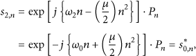

The hardware complexity of the chirp modulator and the matched filter in the transceiver is reduced by using these relationships among subchirps. The proposed architectures are described in Sections 3 and 4 in detail.
3. Architecture of the CSS Transmitter
The CSS transmitter is composed of three essential blocks: the biorthogonal coder, differential phase shift keying (DQPSK) mapper, and chirp modulator.
Biorthogonal codes are utilized to better withstand the effects of various channel impairments, such as noise, fading, and interference. Three bits are mapped to a four-chip biorthogonal codeword (
In this paper, the size of the ROM for the reference subchirp in the chirp modulator is reduced by using the relationships among subchirps mentioned in the previous section. Since the samples of the 1st, 2nd, and 3rd subchirps are generated by the reverse indexed and/or conjugate samples of the 0th subchirp as in Section 2, the samples of the reference subchirp for the chirp modulator are composed of only the samples of the 0th subchirp in the proposed transmitter; as a result, the ROM size is reduced by the amount of 75%.
Figure 3 explains the generation of the four subchirp samples in SOP 1. By only using the samples of the 0th subchirp stored in the ROM, the 1st, 2nd, and 3rd subchirp samples are generated by changing the reading address and sign. In Figure 3,
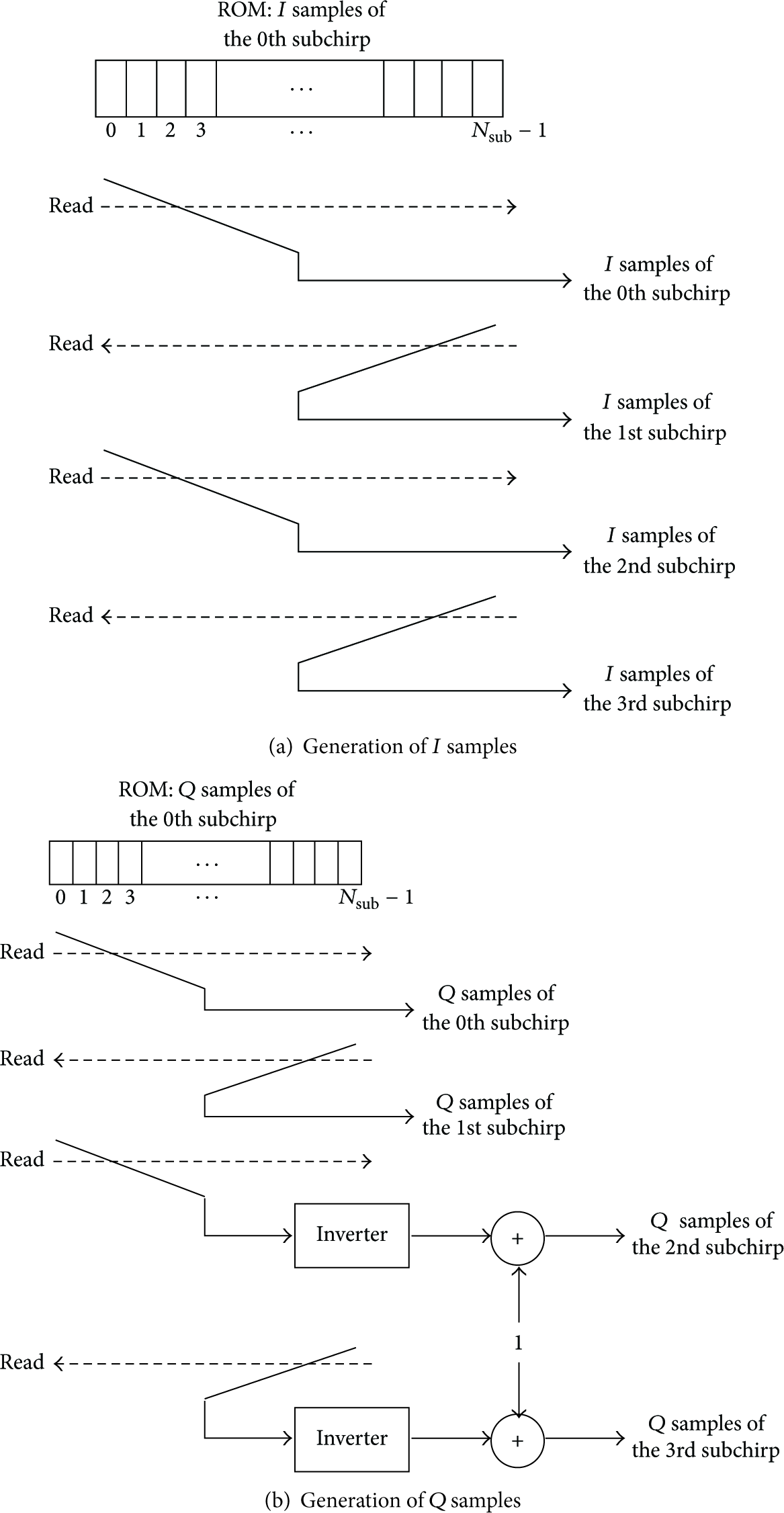
Generation of the four subchirp samples by only using the 0th subchirp samples.
Figure 4 shows the transmitter architecture of CSS. DEMUX denotes the demultiplexer,

CSS transmitter architecture.
4. Architecture of the CSS Receiver
The CSS receiver is divided into six blocks: the chirp demodulator, DQPSK symbol demapper, biorthogonal decoder, time synchronizer, frequency synchronizer, and automatic gain control (AGC).
4.1. Matched Filter for the Chirp Demodulator
Due to the band hopping property of CSS, as described in Section 2, the matched filter should be adopted in the chirp demodulator to remove the other band noise. Since low-complexity implementation is very important for CSS, we propose a new architecture for the matched filter. Using the relations among subchirps in Section 2, the duplicate coefficients of the filter are removed. The coefficients of the filter are composed of only the 0th subchirp samples.
In [12–14], the matched filter is generally implemented using a transposed form since the multiplication of the filter can be substituted by addition and shift. The proposed matched filter also adopts the transposed form.
A symbol of CSS is composed of the four subchirps. Therefore, four subfilters are required for CSS. Since the four subfilters are complex filters, the I and Q channels should be considered separately. The I and Q outputs of the 0th subfilter are expressed by
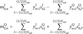
The coefficients of the 1st, 2nd, and 3rd subfilters are replaced by those of the 0th subfilter by using the relations among the subchirps described in Section 2. As a result, the four subfilters are designed by utilizing only the coefficients that are matched to the 0th subchirp. The output sequences of the 1st, 2nd, and 3rd subfilter are presented in the following:

The proposed matched filter is based on a transposed form, which is composed of two parts: a multiplier block (MB) and a register and adder block (RAB). In the transposed form, the hardware complexity of the MB is reduced as in [12–14] because all multiplications are products of a single input multiplicand.
Figure 5 shows the proposed architecture of the matched filter for CSS. The MBs, which are composed of the coefficients matched to the 0th subchirp, are shared by the four subfilters. For I and Q input sequences, there are two MBs that are composed of adders and a shifter as in [12]. The 0th and 2nd subfilters share RABs because of the conjugate relationship between the 0th and 2nd subchirps; eventually, the outputs of the 0th and 2nd subfilters are determined by the adders or subtractors that add or subtract the outputs of shared RABs. The 1st and 3rd subfilters also have the same relationships described above. In the 1st and 3rd subfilters, the reverse blocks change the order of input sequences in order to generate the reverse indexed coefficients. The RABs accumulate the output sequences of reverse blocks.

The proposed architecture of the matched filter.
4.2. DQPSK Decoder and QPSK Demapper
After chirp demodulation, the DQPSK symbol is differentially decoded by using differential multiplication. The QPSK symbol demapping is then performed by multiplying
4.3. Biorthogonal Decoder
Four chips that are generated from QPSK demapping of the four subchirps compose a biorthogonal codeword. The I and Q codewords are independently demapped according to a biorthogonal code table. To find the codeword that has the maximum probability, a code correlator is utilized. The codeword that has the maximum correlation value is selected.
In this paper, a low-complexity biorthogonal decoder is proposed. The code correlator is designed only using an adder/subtractor. The correlation results of the 0th codeword and the 4th codeword have the same absolute value but different signs because of the antipodal relation between the 0th and 4th codewords. Furthermore, the 1st and 5th, the 2nd and 6th, and the 3rd and 7th codewords have antipodal relations; thus, only four code correlators are used and the largest absolute value of the correlation results is found. Then, a final codeword is selected according to the sign of the correlation result.
Figure 6 shows the proposed biorthogonal decoder. The code correlator is designed using eight adders/subtractors. The correlation result that has the maximum absolute value is selected. Then, according to the sign of the correlation result, a final codeword is selected. After the biorthogonal demapping, the selected codeword is parsed.

The proposed biorthogonal decoder.
4.4. Time Synchronizer
In CSS, time synchronization is composed of packet detection and frame detection. The packet detection is performed in the preamble and, following this, the frame detection is performed in the start frame delimiter as in [1]. In packet detection, whether a packet exists or not is decided whereas, in frame detection, an accurate start point of the data in a packet is searched for.
As in [15–17], an autocorrelation-based packet detector is generally used because of its immunity to the channel effect. The packet detector, however, has a problem with the timing metric plateau. Some researchers developed algorithms to resolve the timing metric plateau by altering the normalization method in [18–20].
In this section, we propose a new packet detector using a cross-correlation in order to remove the other band noise caused by the band hopping property of CSS. The timing metric plateau problem is also resolved since the cross-correlation results of subchirps have sharp peaks. The channel effect is suppressed by using the autocorrelation followed by cross-correlation. The cross-correlation results are mathematically expressed in (7). Then, we perform the autocorrelation as in (8). Consider


Using


The start frame delimiter is composed of four symbols, as in [1]. The frame detector in the proposed receiver is designed using a correlator whose input is the output of the chirp demodulator of the start frame delimiter symbol. For low hardware complexity, the correlator is designed only using an adder/subtractor since the code of the start frame delimiter consists of 1 and −1 as in [1].
4.5. Frequency Synchronizer
The frequency offset in CSS should be corrected as in [22]. Due to the band hopping property of the CSS, Baik et al. [22] proposed the frequency synchronization algorithm based on the matched filter. In this paper, we apply Baik's frequency synchronization algorithm to the proposed CSS transceiver.
4.6. Automatic Gain Control (AGC)
The received power of the wireless signal varies due to the multipath fading, interference, and distance, among other factors. Such random variation of the received signal power leads to quantization noise during analog-to-digital conversion in the receiver. The main goal of AGC is to minimize the quantization noise by adapting the received signal power at an appropriate level [23–25]. In this paper, we apply Hui's algorithm that considers both the adaptation time and stability for CSS in [25] for the proposed CSS transceiver.
4.7. Architecture of the Proposed Receiver
Figure 7 shows the proposed receiver architecture of CSS.
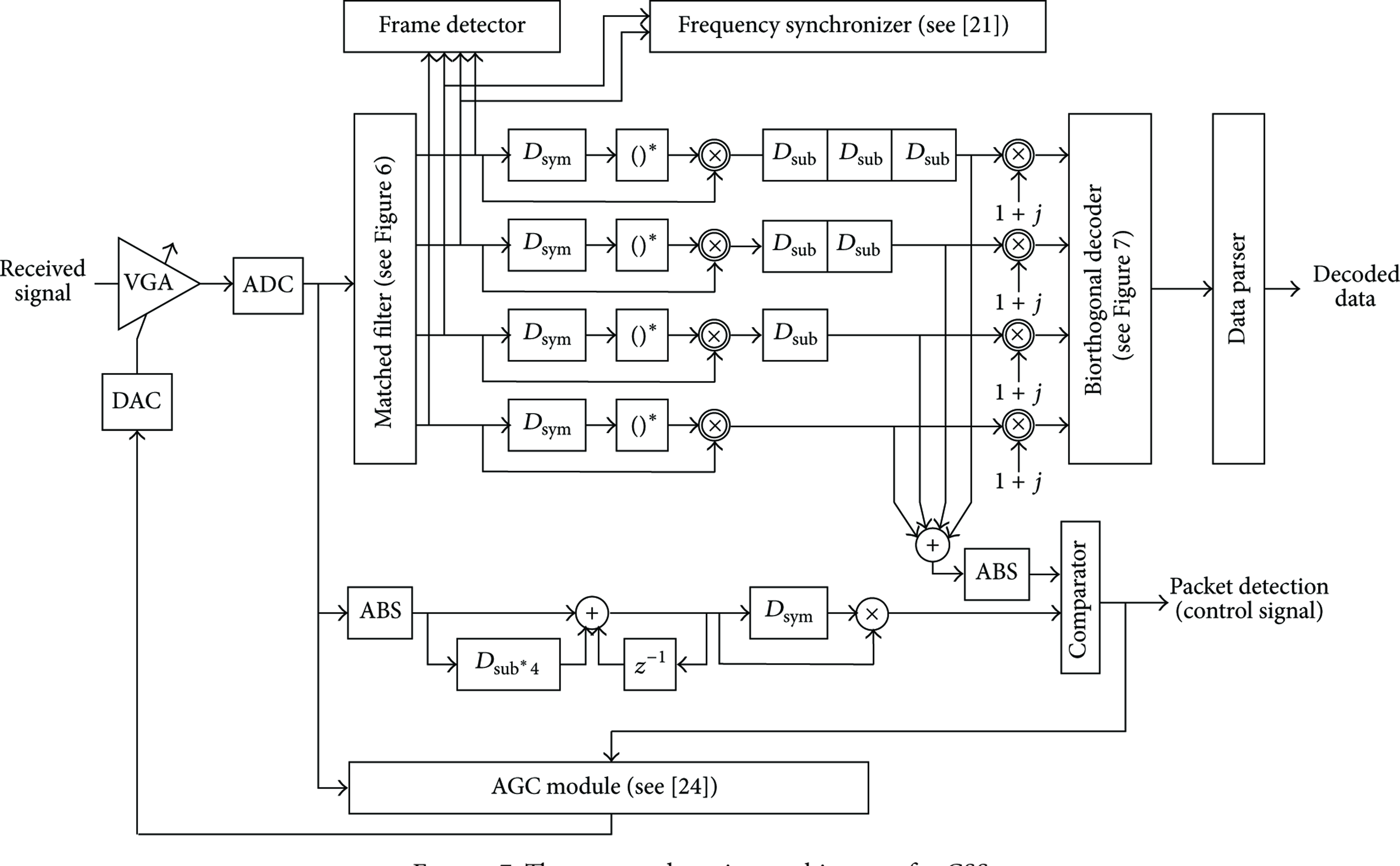
The proposed receiver architecture for CSS.
5. Simulations
In this section, we show the simulation result of the bit error rate (BER) performance of the proposed receiver architecture. The performance of the packet detector is also simulated. We assume that the sampling frequency is 32 MHz in all simulations.
5.1. BER Performance of the Proposed Receiver Architecture
We compare the BER performance of the proposed architecture with those of the conventional ones as described in [11]. In [11], the receiver architecture based on autocorrelation and the receiver architecture that adopts the dual-band filtering method are introduced. Figure 8 shows the BER performances of the proposed and conventional architectures. As in Figure 8, the BER performance of the proposed receiver architecture is better than that of the conventional ones, since the other band noise caused by the band hopping property of CSS is removed by the matched filter.
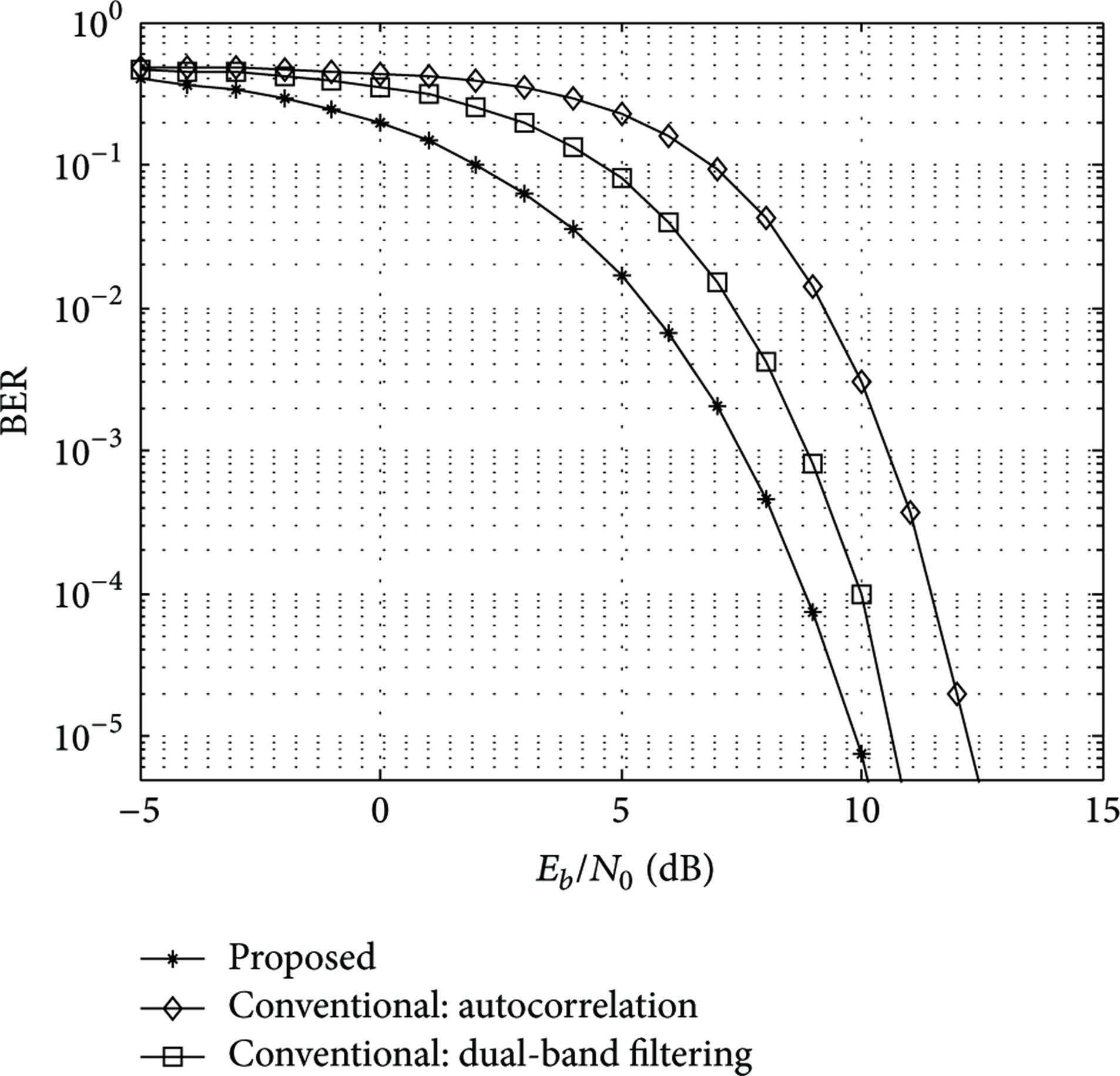
Comparison of BER performances.
5.2. Performance of the Packet Detector
To test the performance of the proposed packet detector, the timing metric and the decision variable are investigated. We compare the performance of the proposed packet detector with that of the detector [15] written by Schimdl and Cox. Two symbols in the preamble of CSS in [1] are used for the simulation. The results of the simulations are averaged over 1,000 realizations.
Figure 9 shows the decision variables of the proposed and Cox's algorithm.

Decision variables of the proposed algorithm and Cox's algorithm.
Timing metric is important factor as in [18–20]. The autocorrelation-based packet detector has a timing metric plateau problem. The timing metric plateau, however, is suppressed by the cross-correlation in the proposed detector. Figure 10 shows the timing metrics of the proposed and Cox's detector. The simulation is performed at 5 dB SNR. The timing metric plateau problem is resolved in the proposed algorithms as in Figure 10.

Timing metrics of the proposed and Cox's detector.
6. Implementation and Test Results
6.1. Implementation Summary
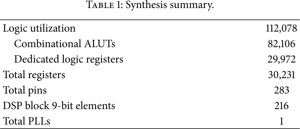
The proposed transceiver of CSS was modeled by Verilog hardware description language and synthesized. Synthesis summary of the proposed CSS transceiver is shown in Table 1.
Synthesis summary.
For test of the designed transceiver, evaluation kit for 2.4 GHz RF circuit and antenna was used. Its low-pass filter bandwidth and low noise amplifier were controlled through serial peripheral interface. All of setting parameters are shown in Table 2.
Experimental parameters for RF circuit.

Simple medium access control (MAC) is implemented in the target FPGA chip. Figures 11 and 12 show the block diagram and the photograph of the test system, respectively.

Block diagram of the test system.
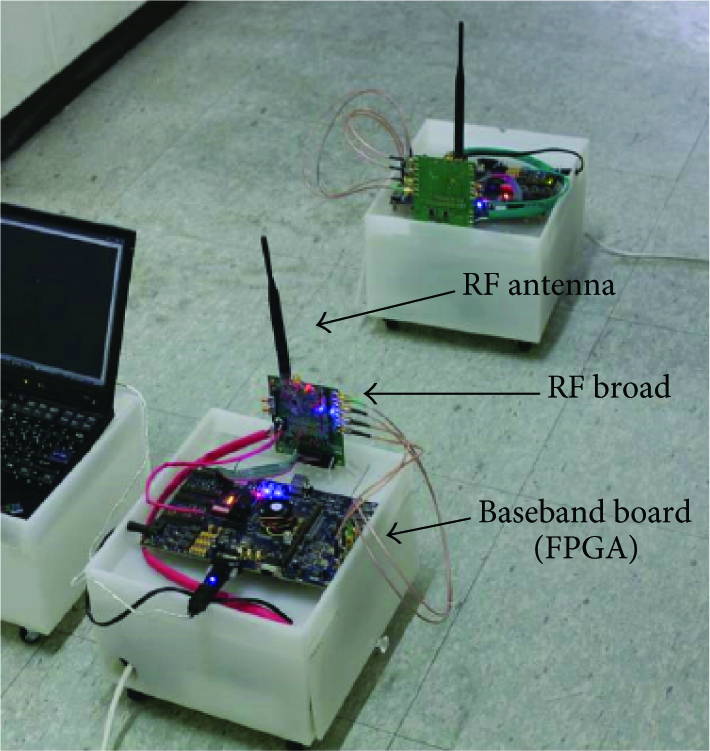
Photograph of the test system.
6.2. Test Results
The spectrum of the CSS signal is measured by a spectrum analyzer as depicted in Figure 13. The spectrum of the designed CSS signal is well-matched compared with that of the simulation in Figure 2.
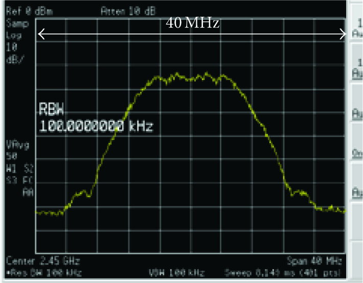
Measured spectrum of CSS.
The received signal passed through the indoor channel is measured by a logic analyzer, as in Figure 14. When the CSS signal is received in the receiver, the signal is first clipped since the variable gain amplifier is set to the noise power level. Then, the power of the signal is adjusted by the AGC module to the appropriate power level. The enlarged time domain waveform of the received CSS signal is also shown in Figure 14.

Measured received signal in the receiver.
The outputs of the 0th submatched filter in the preamble are shown in Figure 15. In the preamble, the transmitted phase is 0. However, the output phase of the matched filter is changed, such as

Test results of the 0th submatched filter.
Finally, the packet detector is tested.

Test result of the packet detector.
7. Conclusions
A CSS transceiver architecture for IEEE 802.15.4a was proposed. The matched filter-based receiver was proposed in order to remove the other band noise caused by the band hopping property of CSS. Low complexity architectures of the chirp modulator, the matched filter, and the biorthogonal decoder were also proposed. In addition, a robust time synchronizer based on the matched filter was presented.
Throughout the computer simulations, we showed the effectiveness of the proposed CSS transceiver architecture. In particular, the BER performance of the proposed receiver was enhanced since the other band noise due to the band hopping property of CSS was removed by the matched filter. Furthermore, the performance of the proposed packet detector was better than that of the conventional one.
We designed and verified the proposed transceiver architecture in the FPGA chip. We confirmed that the proposed transceiver of CSS operates well in wireless environments.
Footnotes
Conflict of Interests
The authors declare that there is no conflict of interests regarding the publication of this paper.