
Abstract
Accurate measurement of hand forces in motorbike riding is highly desirable for studies of safe riding. In this paper, we implement a force-sensing glove system for measuring real-time hand forces during motorbike riding with the aim of giving feedback to the riders. It consists of a pair of gloves with tactile sensors suitably mounted and configured for data acquisition via a wireless smartphone. A novel calibration method is developed for dynamic calibration considering force measurement in natural operation and environments. Consequently, a series of data classification algorithms ensure accurate hand performance feedbacks for motorbike riders. The feedback data could potentially alert the riders to predict and prevent accidents. Validation tests demonstrate that this force-sensing glove system has a strong potential as a tool for hand performance monitoring in real environment.
1. Introduction
Motorbike riding is largely an enjoyable and exhilarating experience, while one of its inherent aspects is the high risk for accidents [1]. A thorough analysis on the predominant cause of accidents has shown that 52% originated from rider error [2]. The primary contributing factors to these statistics are failures in human perception and decision errors, as the motorbike market continues to mature and the need for improved safety increases, resulting in the need for the development of optimum driving control. Unfortunately, the safety measures and conditions generally believed to reduce injury risks may not always function as expected. In particular, riders rely heavily on their hands to control the throttle, front brake, and clutch, in addition to steering the motorbike. These control inputs will significantly change the motorbike's dynamics during riding such that minor changes could result in loss of control. As a result, the evaluation of hand dexterity performance with respect to activities in the environment provides valuable biomechanical information [3].
Recently glove-based measurement systems have become popular for hand performance evaluation. Most systems involve noncontact position measurement devices (typically magnetic, ultrasonic, or optical) for tracking hand movements. In addition, actuators can be deployed to convey force of touch sensations; moreover, an interesting measurement is the force applied to an instrument or tool while manipulating it [4]. Measurement in more natural environments would increase the efficiency of various interventions [5]. Though different types of force transducers exist, tactile sensors are thin, lightweight, and flexible, making them ideal for integration into human wearable technology, which have been reported as being more efficient and user friendly in applications [6]. Tactile sensors placed on the fingertips of gloves for measuring surface hardness and pressure can be used to sense finger position [7] and recognize different objects [8]. Typically, force glove systems containing an array of tactile sensors are developed for grip force tasks. They measure finger and phalangeal forces for optimal cylindrical handle diameter [9] and evaluate the effect of handle shapes on maximum pulling for optimizing hand tools [10]. Hence, through the motorbike activities, tactile sensors could be the most ideal for force-sensing than any other type of sensors. Due to the lack of reliable information on motorbike gloves, it is extremely important to continue research and development of relative equipment [6].
Traditionally, precise measurements of hand biomechanics (kinematics and kinetics) were made in the laboratory. They are usually cabled to a data acquisition computer and thus restrict the wearer's movements in natural environment. In recent years, wearable computing is fast emerging as a next-generation technology for ubiquitous monitoring of human performance [11]. Performance statistics motivate and allow riders to keep track of their progress between workout sessions while frequent and concurrent feedback information during training can help to improve the performance of riders. Wearable sensing can break new grounds in the design of technologies that sense and analyze body movements and that immediately provide feedback.
In this paper, we focus on force-sensing gloves which can provide real-time feedback for adjusting the hand performance during motorbike driving which have not been explored in detail. It is based on development of glove worn sensors to discriminate various motorcycle operating functions such as clutch, throttle, brake, and steer. Our work addresses three tasks: (1) Taking advantage of advanced computing capability and wireless communication of Bluetooth built-in of smartphones, we developed wearable hardware tool that automatically sensed the riders' hand movements. (2) While there is not adequate understanding of the performance of tactile sensor integrated into a force-sensing glove system, a prior proper calibration method and a reliable process to deal with the force values were performed for reliable use of force-sensing glove system. (3) Development of software tools for performance corrections in rapid evaluation of tactile motion biofeedback was performed.
2. Experimental Section
2.1. The Force-Sensing Glove System
The prototype system is a lightweight measurement device designed to measure hand performance automatically. This system is composed of a portable subsystem and a remote unit (Figure 1). The portable device consists of two gloves with 4 tactile sensors attached onside each glove and connected to a microcontroller through front-end electronics. The sensor was mounted on the palms and fore fingers to measure the major activities during motorbike riding. The management of the sensor measurement is assigned to the microcontroller that performs several functions: interfacing and conditioning of signals from the sensor block and data transmission. During the operation, the remote unit (the smartphone used in this research) converts, records, and displays the received force measures data.
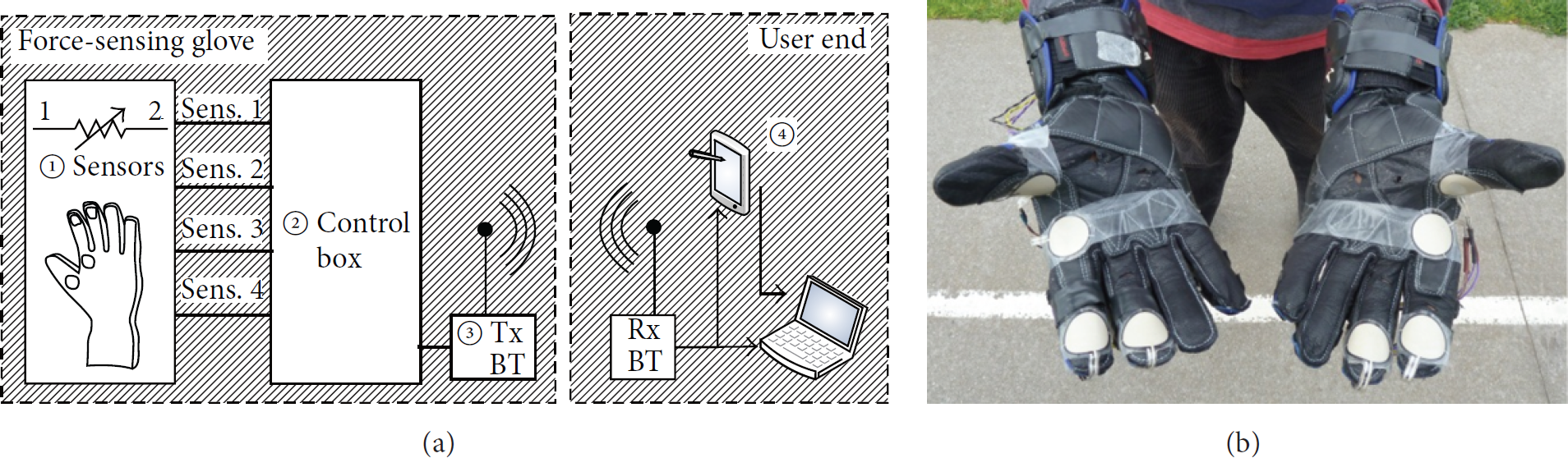
(a) Block diagram of the proposed system (① four flexi-sensors for one glove, ② chipboard with a MCF51 chip, ③ a Bluetooth transceiver, and ④ a smartphone or a laptop). (b) The prototype force-sensing gloves.
The most important requirements for the force-sensing glove system include low cost and lightweight construction, unencumbered movement on operating motorbike during data collection, and unobstructed sense of touch on the palms. In the present configuration, four A401 Flexi-Force tactile sensors (Tekscan, Inc., South Boston, MA) were attached as in Figure 1(b) to measure tactile forces. Two tactile sensors were placed on index finger distal phalanx (ID) and middle finger distal phalanx (MD), respectively, so that they are applied in the monitoring of the activity of two-finger braking [12]. Such braking action is used most commonly by riders because of its benefits including reduced braking reaction time and simultaneous use of throttle and brakes. It generally gives riders a firm grip on the throttle. The other two force sensors are integrated on palm (P) and thumb proximal phalanx (TP) of the glove surrounding the throttle; therefore the rotation of throttle can be observed from two force signals [3]. The A401 Flexi-Force sensor is a commercial light-weighted foil product which weighs only 0.33 g, with an active area diameter of 25.4 mm and 0.2 mm thickness. All tactile sensors are separately connected to the conditioning/signal-processing circuit block using twisted pair cable. The electrical noise going into or coming from the cable can be prevented to an extent. All tactile sensors are interfaced to the smartphone wirelessly via Bluetooth protocol.
The microcontroller is the MCF51JM128VLH (Freescale Semiconductor Inc., West Austin, TX). This commercialized device is a 32-bit reduced instruction set computing (RISC) microprocessor and an ultralow power microcontroller. It operates at processor core speeds up to 50.33 MHz. The operating supply voltage is between 2.7 V and 5.5 V. The Bluetooth transceiver is a Parani-ESD 200D (Sena Technologies, Inc., San Jose, CA) and its operating supply voltage is 3.3 V. Bluetooth standard was specifically proposed by the SIG to fulfill a need for extremely lower power, lower data transmissions for wireless sensor networks monitoring, and most of glove-based system [5]. Bluetooth technology feasibly supports real-time and wireless hand activity recognition with a mobile device. The adopted bidirectional transmission is not encrypted and is asynchronous. Authentication and error detection are not implemented as well. Parani-ESD200 has a built-in on-board antenna and provides an antenna connector for longer distance communication. Another reason for adopting Bluetooth standard is to perform data collection from both gloves synchronously. With the Android 4.0 version operation system, a smartphone can communicate well with the Bluetooth hardware and millisecond-level synchronization between the wireless devices can be achieved.
The wearable portion of the system weighs approximately 145 g (four sensors + wires: 40 g, signal conditioning circuit with packaging + battery: 105 g). The entire system (including sensors and signal conditioning hardware) is powered by a Li-Ion battery, which is sufficient for a minimum of 8 hours of data collection. There are sensor nodes that connect to the body and record physiological parameters before wirelessly transmitting the recorded signals to a smartphone, PC, or another computer. The power consumption of the sensor node is a critical factor in realizing the smaller device size with the longer operating lifetime, which in turn affects the ease of use. Table 1 summarizes the specifications of three typical batteries which are potentially suitable for powering glove-based system. The physical size, which is discussed above, dominates the device volume and the energy storage capacity, typically expressed in mA-hours. Though capacity is lower than others, Li-Ion battery is better in size and weight. Duration tests also show that over 8 hours of battery life is enough for daily use of our glove system with Li-Ion battery. Hence Li-Ion battery is the best choice for our force-sensing glove system.
Specification of batteries potential for wireless glove-based system.

Data acquisition software (as shown in Figure 2 a real-time monitoring of the glove activity) was also developed for hardware setup. Human interaction with the system is facilitated through the smartphone software. The four plots demonstrated the clutch, brake, steer, and throttle of the motorbike, respectively.

Real-time data acquisition interface of the force-sensing gloves.
The dual purpose smartphone software is responsible for logging the data collected from the glove and visualizing the data. The user interface was built using JDK and eclipse IDE in Android 4.0.4 development environment. The application is capable of performing common Bluetooth operations. The raw data was logged to comma separated value (CSV) files. The software incorporates visual displays of the tactile sensors; the amount force of each hand activity is indicated with color and any emergent event is indicated with sound alarms [6]. In this research, raw data sampling was initially performed at 20 Hz, as generally suggested sampling frequency in other similar works [5, 13].
2.2. Calibration Tests
It is necessary for force-sensing glove system to be calibrated before application to reduce inaccuracies. Most existing force-sensing gloves are calibrated under static conditions [14]. However, since loadings are dynamic in typical applications, dynamic measurements are indispensable in this study. The calibration tests herein include both static and dynamic protocols.
2.2.1. Static Calibration Tests
At this stage of the process, weights load was applied on a load cell with a tactile sensor attached onside in order to obtain a relation between the applied force and the output data of force-sensing glove via wireless connection. The applied force was consecutively varied every 0.5 kg, starting from 0 kg up to 5 kg and then decreasing back to 0 kg. As the maximum single finger force is around 50 N [9, 10], 5 kg has been considered as the limitation for sensor measurement. The test was repeated 10 times. Measurements from the force-sensing glove system were collected for 10 seconds at a sampling rate of 20 Hz. After unloading the weight, a break of 2 minutes was taken before the next trial to eliminate any influence of sensor drift, which could be evaluated by considering amplitude and environmental changes.
2.2.2. Dynamic Calibration Tests
During the calibration, operator wearing the glove upright placed the sensor on a load cell and smoothly applied a continuously changing force. The load cell (Xtran Load Cells S1W force transducer, Applied Measurement Australia Pty. Ltd., Melbourne, Australia) was fixed on a vibration isolation table with screws. Data of load cell were transmitted to NI USB-6002 data acquisition adapter (National Instruments Corporation, Austin, USA) via an amplifier (Figure 3(a)) [15], then uploaded, and recorded by Ni LabVIEW signal-express 2013 software (National Instruments Corporation, Austin, USA) at 20 Hz, which was the same as the sampling frequency of the force-sensing glove. Then, the measurements of the force-sensing glove system were synchronized with corresponding load cell measurements (Figure 3(b)). Data stream synchronization was confirmed by a tap with the first finger so that a large spike in the sensor data streams from both the force-sensing glove and the load cell marks the start and/or the end of the measurement streams. Unlike manual operation in traditional measurements under static conditions, streams from both the force-sensing glove and the load cell are synchronously and automatically collected in the same window. One advantage is that it avoids operative error.
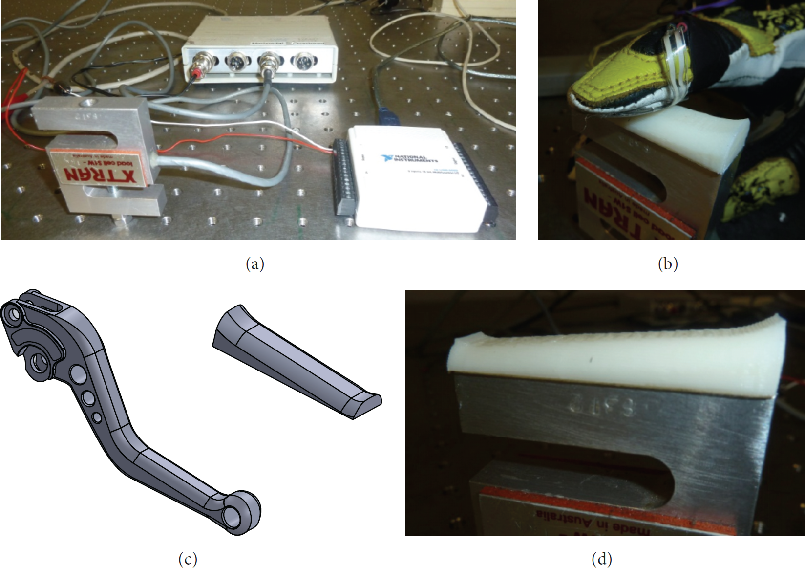
Calibration. (a) The total setup of testing environment. (b) For the force sensor calibration, finger puts on the surface of a real motorbike brake 3D printed model. (c) Built clutch models in SolidWorks. (d) The load cell which was fixed with a 3D printed model which provides similar touching surface of natural environment.
Since the tactile sensors intrinsically react to pressure, the contact area had to be restricted (made constant) by the introduction of an intermediate activator surface. It was necessary to provide a contact area close to the real environment use for the force-sensing glove system. A model (Figure 3(c)) capturing true geometrical aspects of a motorbike handle or clutch was developed with SolidWorks 2013 (Dassault Systèmes SolidWorks Corp., France) and then 3D printed in ABS plastic. This realistic solid model was fixed to the working plate of the load cell (Figure 3(d)). With the assistance of 3D printed model, the sensing area of the sensor under calibration is fully covered for a reliable calibration.
Four healthy subjects, aged 28–40 years, with no movement disorders in the hands participated in the calibration and reliability studies. All subjects received verbal and written descriptions for all procedures. Calibration was performed for each subject matching with each sensor. Subjects were familiarized with the apparatus and given a demonstration by the operator. In every test set, subjects were required to continuously apply vertical and gradually increasing pressure on the load cell for 10 cycles following an acoustic start signal.
2.2.3. Data Analysis
To quantify the accuracy and linearity, mean difference (MD%) and
2.3. Force-Sensing Glove Performance Evaluation
2.3.1. Hand Movement Recognition
Our investigation in tactile motion instructions addressed the composition of tactile patterns that could be used for representing hand movements in an intuitive way. Based on force-sensing, we can distil recommendations for composing tactile patterns that could represent specific hand movements.
The algorithm in Figure 4 worked as follows.
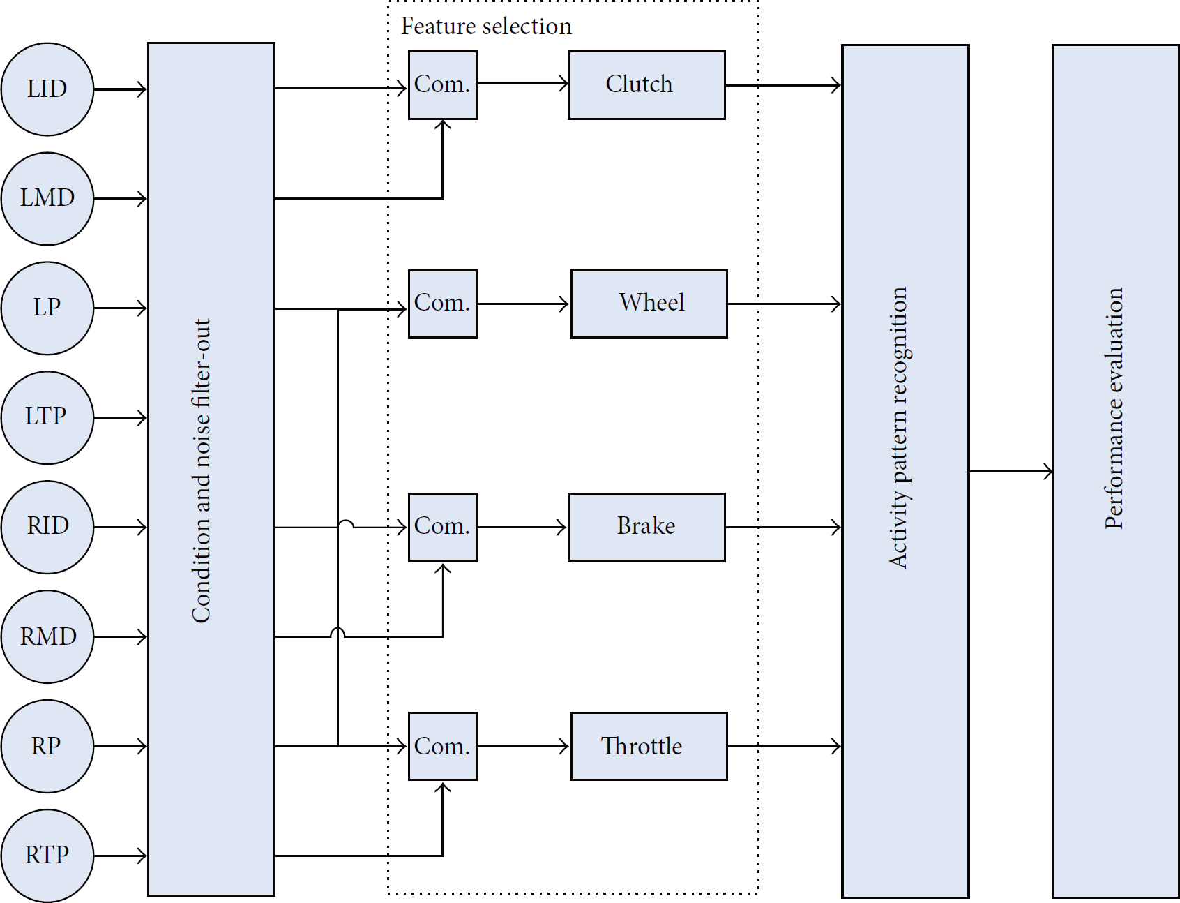
Flowchart of the activity classification algorithm for hand performance evaluation. For hand movements that could serve as general instructions. Every movement has a corresponding countermovement.
First, the sensing element recorded on the ID, the MD, the P, and the TP of the left hand (L) and the right hand (R) was computed:

Then, a threshold of 10% of the maximum expected signal 
As a result, the value 0 became the new reference value for all measurements. Then the forces measured under different places.
For brake and clutch, each of the two sensors is placed and works in the same direction. The resultant force 
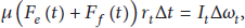
For the steer, it is rotating about a fixed symmetry axis, and its angular momentum is expressed as the product of the moment of inertia of the object and its angular velocity vector:

For the throttle, it also is rotating about a fixed symmetry axis. But the rotation is caused by friction, and thus the angular momentum is expressed as the product of the moment of inertia of the object and its angular velocity vector:
2.3.2. Verification Tests
One healthy subject was enrolled in the below tests, his age is 22 years, and he has no hand movement disorders. He drove a motorbike in a 400 m straight road, wearing a pair of force-sensing gloves and a Gopro2 camera. The rider repeated trials between the start point and the end point at different final velocity (60 km/h, 80 km/h, and 100 km/h in different trials); each time he started from motionless and then accelerated to the assigned speed. The rider repeated all of these movements eight times for every velocity. A smartphone was attached to the back seat of the motorbike (Figure 5) and simultaneously collected data from all tactile sensors.

Overview for hand performance test.
There are three main metrics that are used to assess the operation.
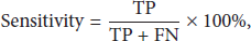
The sensitivity is the main performance metric and shows how many of the actual events are correctly detected:
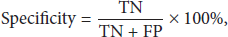
The specificity shows how many nonevents that should not be detected are indeed not detected:
The selectivity shows what fraction of all of the detection incidents made is in fact correct:

3. Results and Discussion
3.1. Tactile Sensing Performance
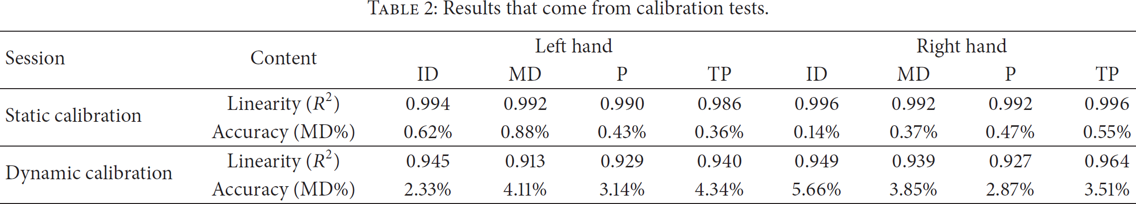
The static calibrations in this study validate the feasibility of the wireless force-sensing glove system in force measurement for solid and flat surfaces. Similar to most relevant studies [13, 15, 16], the static calibration tests as recommended in the User's Manual were efficiently accurate and reproducible. The tactile sensors demonstrated reasonable accuracy (MD% = 0.14~0.88%) and linearity (
Results that come from calibration tests.

Data for static calibration test.
Tekscan sensors are useful and reliable tools once the calibration has been optimized for their application, and calibration should be conducted under conditions as similar as possible to those used in force measurement [13–15]. A new calibration method was developed for synchronous measurements, for forces applied to an uneven surface, that is, motorbike handle. In the development of this calibration process, diverse behaviors had to be considered in order to obtain an acceptable force measurement in the natural environment.
Hysteresis, although not eliminated, is effectively compensated when data from force-sensing glove and load cell are acquired simultaneously. Hysteresis is the difference in the sensor output response during increased loading and decreased loading at the same force [13]. Sensor drift compensation was considered for static measurements, while hysteresis compensation was performed for dynamic measurements [15]. Since data acquisition depended on the experimental protocol (sensor type, interface shape and materials, sensor range in use, loading method, etc.), sensor physical characteristics and behavior should be investigated separately to avoid any potential errors. Hysteresis for all tactile sensors varied from 5.45% to 13.10% in static calibration while they varied from 1.46% to 4.27% in dynamic calibration. The effect is significant enough to warrant calibration of the force-sensing glove for each use to permit reliable repetition of dynamic force data acquisition.
Curved surfaces such as the motorbike handles were of concern since the force sensors would be subject to physical deformation even when no force was applied. Since interface forces happen between support surfaces, glove garments, and the skin, the surfaces of the skin are commonly uneven, and the curvature unavoidably changes the output of the tactile sensors [13]. As shown in Figures 7(b) and 7(d), it has a strong linear connection between the data from force-sensing glove system and the load cell. As noncontact area and slipping occur on curved surfaces of clutches, wrong detection consequently occurred which caused outlier points in scatter plots for sensor placed on the thumb proximal phalanx (Figure 7). Unlike flat brake or clutch surface touched by the sensor on the index finger distal phalanx, handlebar surface is more uneven and similar to cylinder. Ferguson-Pell et al. [13] conclude that the outputs of the sensor changed when the pressures were applied to the curved surface. In this study, the results show that there is no significant difference from the flat surface when the radius of the curved surface was less than 10 mm (the radius of the 3D model is 10 mm). Compared with the recognition results in Table 3, there is no significant influence by different surface in our calibration measurements; the reliability of the tactile sensors shows some decrease in dynamic calibration (Table 2). The simulated surface in our dynamic calibration exposes the influence to a great extent. When comparing our results with the literature [16], the accuracy (MD% = 2.33~5.66%) and the linearity (
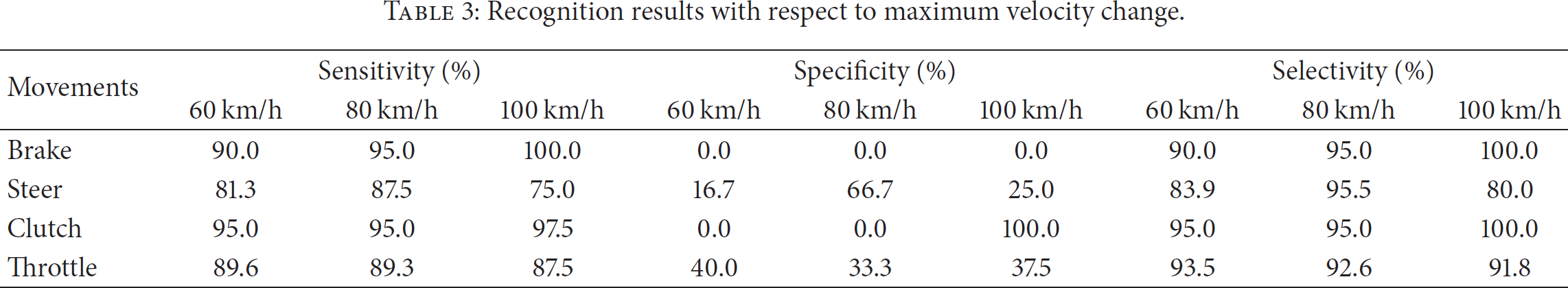
Recognition results with respect to maximum velocity change.

Typical dynamic calibration results for sensors on index finger distal phalanx and thumb proximal phalanx of the same subject's left hand. (a) Data of sensor on index finger distal phalanx by both measures. (b) Correlation of data from two measures. (c) Data of sensor on thumb proximal phalanx by both measures. (d) Correlation of data from two measures.
Despite considerable effort and many attempts to calibrate these sensors, the results were not perfectly satisfactory. The new calibration method was deemed necessary for force-sensing glove that would be sufficiently accurate and reproducible to enable quality research to be conducted in motorbike hand performance measurement. The force-sensing glove system is a potential attempt for motorbike operation after calibrations in static and dynamic conditions.
3.2. Force-Sensing Gloves' Performance
Off-line data analysis reveals that it is possible to differentiate hand movements based on the results between the velocity changes and the force data (Figure 8). In fact, hand movements recognition is challenging from the data stream of the force-sensing glove. The velocity changes during riding are superimposed on the hand movements making separation for recognition difficult. Compared to force information, hand movements messages are minor. The algorithm reported data in four groups.
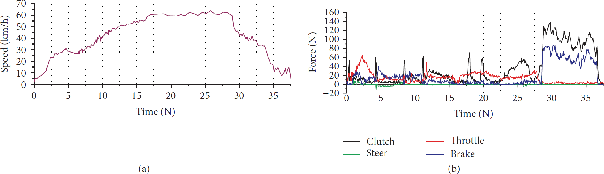
Typical performance results from a straight speed up to 60 km/h and speed down trial. (a) Speed data integral from accelerate of smartphone, (b) force data result from force-sensing gloves. As shown in this demonstration. During 0–4 s, there was a rapid acceleration and a bit right turn after shift up. During 4–8 s, there was an adaption which included a left turn and a bit brake. Accelerate during 8–16 s and keep the speed over 10 seconds during 16–28 s. Before brake for speed down, there was a continuous shift down. Finally there was brake movement for about 8 seconds.
The accuracy data of the recognition algorithm were assessed through a one-by-one comparison of its output with the expected results derived from manual annotations of videos. Table 3 summarizes the recognition accuracy for the test set. Results indicated that overall accuracy of the recognition algorithm is over 80%. The force-sensing glove performs good sensitivity in hand activity recognition.
The developed algorithm used a threshold test and empirically chosen parameters for the hand movement classification. This method is simple when compared to machine learning algorithms that consider sensor data variability. Even so, most of hand movements were correctly recognized in the test set, which comprised records with different speeds. The rate of wrong detection increased particularly for hand movements of steer and throttle. It was necessary to improve the setup of the force sensors and adjust threshold parameters to improve recognition. Although our algorithm correctly classified hand movements with high accuracy, we conjecture that other external sensors are required to assist with event detection, for example, the built-in accelerometer in the smartphone. Future work will focus on more movement experiments under real motorbike riding tests coupled with further sensors for event detection and movement recognition.
After providing a comprehensive understanding of the performance characteristics of the various force glove measurement system, the aim of this study is to estimate the influence of finger force and predict potential accidents to handle the racing motorbike activities. This force-sensing glove system furnishes sufficient data to build a feedback sensor network for the safety of motor divers and determine an optimal handle shape for motorbike riding.
Furthermore, the alerting threshold could be customized by the riders' subjective assessment during the test. These types of riding assistance improve the judgment of a safe driving approach and achieve the intelligent speed adaptation. This force-sensing glove system furnishes sufficient data to build a feedback sensor network for the safety of motor divers and determines an optimal handle shape for motorbike riding.
4. Conclusions
We developed a wireless force-sensing glove and demonstrated that the system is properly working as regards data communication, static calibration, and partially dynamic calibration. We proposed an approach to merge the results coming from the different sensors during motorbike riding.
To ensure reliability of the force-sensing glove, the present study provides a comprehensive understanding of the calibration of the force-sensing glove system. 3D printed parts were used to provide more realistic contact surfaces, that is, clutch and handle bars. The calibration process provided data on sensor drift and hysteresis of the force sensitive sensors for curved surfaces.
With the real-time classification algorithms employment, the accuracy of hand activity recognition reached 80%, on average. Our force-sensing glove achieves a wider range of recognition capability which is capable of recognizing both force feedback information and hand activities simultaneously. The four major feedback factors including clutch, brake, steer, and throttle contribute to the sophisticated force-based system during the motorbike movement, which could be integrated to a distribution sensor network for avoiding the predictable accidents. Even in high-speed working environment, the force-sensing glove still works well.
Footnotes
Conflict of Interests
The authors declare no conflict of interests.