
Abstract
The IEEE 802.15.8 provides peer-aware communication (PAC) protocol for peer-to-peer infrastructureless service with fully distributed coordination. One of the most promising services in IEEE 802.15.8 is group multicast communication with simultaneous membership in multiple groups, typically up to 10 groups, in a dense network topology. Most of the existing multicast techniques in mobile ad hoc networks (MANET) have significant overhead for managing the multicast group and thus cannot be used for fully distributed PAC networks. In this paper, we propose a light-weight multicast routing protocol referred to as a fully distributed multicast routing protocol (FDMRP). The FDMRP minimizes routing table entries and thus reduces control message overhead for its multicast group management. To balance the control message, all nodes in the network have a similar number of routing entries to manage nodes in the same multicast group. To measure the effectiveness of the proposed FDMRP against the existing schemes, we evaluated performance by OPNET simulator. Performance evaluation shows that the FDMRP can reduce the number of routing entries and control message overhead by up to 85% and 95%, respectively, when the number of nodes is more than 500.
1. Introduction
Due to the proliferation of smartphones, cellular networks have experienced a 5,000 percent surge in mobile data traffic in the last three years [1]. Mobile data offloading is the use of complementary network technologies to deliver mobile data traffic originally planned for transmission over cellular networks by using device-to-device direct communication. With this requirement, the IEEE 802.15 standards group has established Task Group 8 (IEEE 802.15 TG8). The IEEE 802.15.8 standard defines PHY and MAC mechanism for wireless personal area networks (WPAN) peer-aware communications (PAC) optimized for peer-to-peer and infrastructureless communications with fully distributed coordination.
PAC is a special type of MANET techniques and its features include (1) discovering peer information without association, (2) discovery signaling rate, typically 100 kbps, (3) being scalable with respect to the number of devices and data rate, (4) group communication with simultaneous membership in multiple groups, typically up to 10, (5) relative positioning, (6) multihop relay, (7) security, and (8) being operational in selected globally available unlicensed/licensed bands below 11 GHz capable of supporting these requirements [2]. The applications for PAC will be diverse and may include social network services (SNS), local advertisements, games, streaming applications, proximity device control, P2P services, and emergency services as in Table 1. In Table 1, most of the applications require multicast technique that supports multihop transmission. For these reasons, the PAC necessitate a fully distributed multihop multicast protocol.
The PAC application matrix [3].

In terms of MANET, there are a large variety of multicast protocols in the literature. We can classify them into two approaches: tree-based and mesh-based ad hoc multicast routing protocols. The tree-based ad hoc multicast routing [4–10] is a technique where a root node manages a multicast group based on a tree. Since the root node manages the multicast tree, it consumes resources such as memory, power, and control messages. Also, management cost of tree-based multicast routing is high because it is hard to change the structure of the tree to support mobile nodes. Moreover, if the root fails, then the multicast group has to elect a new root node to reconstruct the tree.
In order to support a high mobility environment, more recent multicast routing protocols use a mesh network [11–17]. Multicast protocols using mesh networks usually provide multipath links to nodes within a multicast group. For this reason, mesh-based multicast routing protocols can respond quickly to link breakage due to mobility. However, a mesh-based protocol imposes two major problems. First, to support multipath links, each node has to store a significant amount of information for neighboring nodes and routing information for the multicast group. Second, the computation overhead of a node in a mesh-based protocol is larger than in a tree-based protocol because there are multiple transmission paths.
These multicast protocols are not suitable for PAC because existing multicast routing protocols for MANET have some problem. In tree-based protocols, node has to manage a multicast group tree. Since one of the PAC features is fully distributed coordination, tree-based multicast routing is improper for PAC. In case of mesh-based multicast protocols, there are two problems as mentioned. Moreover, mesh-based multicast routing protocols consume a lot of power from control messages to manage most of the nodes within a multicast group. Since there is a lack of memory and battery-based devices, mesh-based multicast routing protocols are not suitable for PAC.
To overcome these problems, in this paper, we propose a light-weight multicast routing protocol referred to as fully distributed multicast routing protocol (FDMRP). In FDMRP, we assume that all nodes are deployed in fully distributed manner and they maintain routing table to support multihop. Under the assumption, the FDMRP tries to minimize the number of routing entries and optimize memory space and reduce power consumption for managing a multicast group. By using the above approach, we can reduce periodic control messages to support mobile nodes.
The remainder of this paper is organized as follows. We survey the existing related work in Section 2. In Section 3, we describe the proposed FDMRP in detail. In Section 4, we describe theoretical analysis with discrete Markov chain model. Section 5 evaluates performance of the FDMRP compared with existing schemes. Finally, we draw conclusions and suggest future directions in Section 6.
2. Related Work
To facilitate the analysis of multicast protocols, we can classify them into three approaches: tree-based [4–10, 18], mesh-based [11–17], and hybrid-based ad hoc multicast routing protocols [19, 20]. Ad hoc multicast routing protocol utilizing increasing ID-numbers (AMRIS) [8] falls under the tree-based approach. AMRIS assigns every node in a multicast group with an ID-number and makes multicasting tree. This ordering between ID-numbers is used to direct multicast traffic and quick local repair for the multicast tree. Another tree-based multicast protocol by a cross-layer designed approach [5] uses multipoint relays (MRPs) for MANET. The source node selects some MPRs among its 1-hop neighbor nodes and these MPRs can cover all 2-hop neighbor nodes of the source node. Continuously, each MPR selects the next MPRs. As a result, a protocol has a tree formation. Multicast ad hoc on demand distance vector (MAODV) [6] has a multicast group leader for managing a group. The multicast group leader periodically broadcasts group hello (GRPH) message to the multicast group members to forward information. Ad hoc multicast routing protocol (AMRoute) [9] uses logical cores. Specific tree nodes are designated by AMRoute as logical cores and are responsible for initiating and managing the signaling component of AMRoute, such as detection of group members and tree setup. Extendable multicast routing protocol (EMRP) [7] is used for hierarchical multicasting in MANET environments. This protocol uses the subsource to reduce the paths among receivers. The aforementioned tree-based multicast routing protocols are very simple and their network structure is easy to set up. However, these protocols have to reconstruct the entire tree when the link failures occur. This situation will become severer when nodes are mobile. Additionally, maintaining a shared tree loses path optimality. On the other hands, maintaining multiple trees to support many source nodes imposes significant overhead such as memory, power, and control messages.
Unlike the former, there is no root note in the mesh-based multicast routing protocol. Mobility-based hybrid multicast routing (MHMR) [11] joins a cluster communication mesh. In their scheme, several nodes formed a cluster and they elect a cluster head node. In the cluster, all nodes are connected with mesh link and the cluster head node manages its own cluster members. If a cluster member wants to communicate with the other cluster member, it can communicate through its cluster head node. Core-assisted mesh protocol (CAMP) [13] is another mesh-based protocol. This protocol is proposed to solve the weakness in a tree-based multicast routing protocol. CAMP provides the multipath and the core maintains the mesh network. In network sender multicast routing protocol (NSMRP) [17], a sender transmits its multicast data frames to a special node which is called the mesh sender (MS). In turn, this MS takes the responsibility of delivering the messages to all group members in the network. On demand multicast routing protocol (ODMRP) [16] is distributed mesh-based protocol. Since the ODMRP provides the multipath for receivers, the ODMRP is robust for the link breakage and channel error. However, the ODMRP has a significant weakness if all the source nodes flood the Join-Q message for maintaining the routing group. Therefore, the control overheads are larger than tree-based or other mesh-based multicast routing protocols. Moreover, since all receiver IDs are saved in the routing table, more memory is used for the routing table. As observed, mesh-based multicast routing protocol requires more control messages than the tree-based approach. As a result, it imposes power inefficiency, network load, and control overhead.
Hybrid-based multicast routing protocols combine with the advantages of both tree- and mesh-based approaches. Efficient hybrid multicast routing protocol (EHMRP) [19] separates data forwarding path from join query forwarding path by incorporating low overhead local clustering technique to solve the scalability issue. However, this protocol has significant overhead for clustering when the nodes have mobility. Additionally, there have been a variety of multicast routing protocols based on application dependence. These multicast routing protocols can be divided into QoS [21], energy-efficiency [22–24], network-coding [25], and reliable multicast [26]. However, this type of research is not applicable to PAC scenario since the PAC is targeting an application where the PAC nodes have light-weight routing entries and thus reduce control message overhead under the mobile environment.
As observed, the existing techniques are not appropriate for PAC networks especially because of bad scalability in densely deployed distributed topology. In order to consider the routing overhead, in this paper, we proposed light-weight multicast routing protocol for fully distributed networks. Our scheme minimizes the number of routing entries to reduce control overhead under the mobile environment and unnecessary control messages.
3. Fully Distributed Multicast Routing Protocol
3.1. System Model and Basic Assumption
In the FDMRP, we assume a multihop mesh topology consisting of N PAC devices (PDs) in
3.2. Multicast Group Management
3.2.1. Finding/Joining Multicast Group
A multicast group consists of two or more PDs with the same application type ID (
(1) (2) Broadcasts an ACF (3) (4) (5) (6) (7) (8) (9) (10) (11) (12) Save routing entry for the originator of the ACF; (13) Multicast MGNF (Type: 0); (14) Reply ARCF through backward path; (15) (16) (17) Decrease the TTL of the ACF and forward the ACF to neighbors; (18) (19) (20) (21) Save routing information for originator of the ARCF; (22) Become a multicast group member; (23) (24) Save routing information for originator of the ARCF; (25) Become a fowarding PD; (26) Forward the ARCF to the destination of the ARCF; (27) (28) (29)
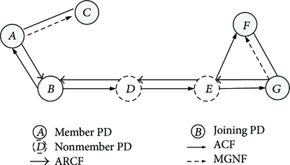
The multicast group joining procedure of the FDMRP.
By proposed joining procedure, we can reduce the number of routing entries since each PD maintains entries only for PDs that has exchanged ACFs and ARCFs in its routing table. Figure 2 shows an example of the number of routing entries when we use our proposed joining procedure. In Figure 2(a), all member PDs maintain entries for other member PDs. Additionally, forwarding PDs maintain entries for member PDs as well as forwarding PDs. Therefore, the total number of entries is 40. On the contrary, in Figure 2(b), each of the member PDs A and D only maintains entry for PDs D and A, respectively, because they exchange ACF and ARCF. Since they do not exchange ACF and ARCF with other member PDs (e.g., PDs E, G, and I), they do not maintain entries for other member PDs. Similarly, since nodes E, G, and I exchange their ACF and ARCF, node E only maintains entries for PDs G and I. Then, the proposed technique can reduce the routing table size as 16.
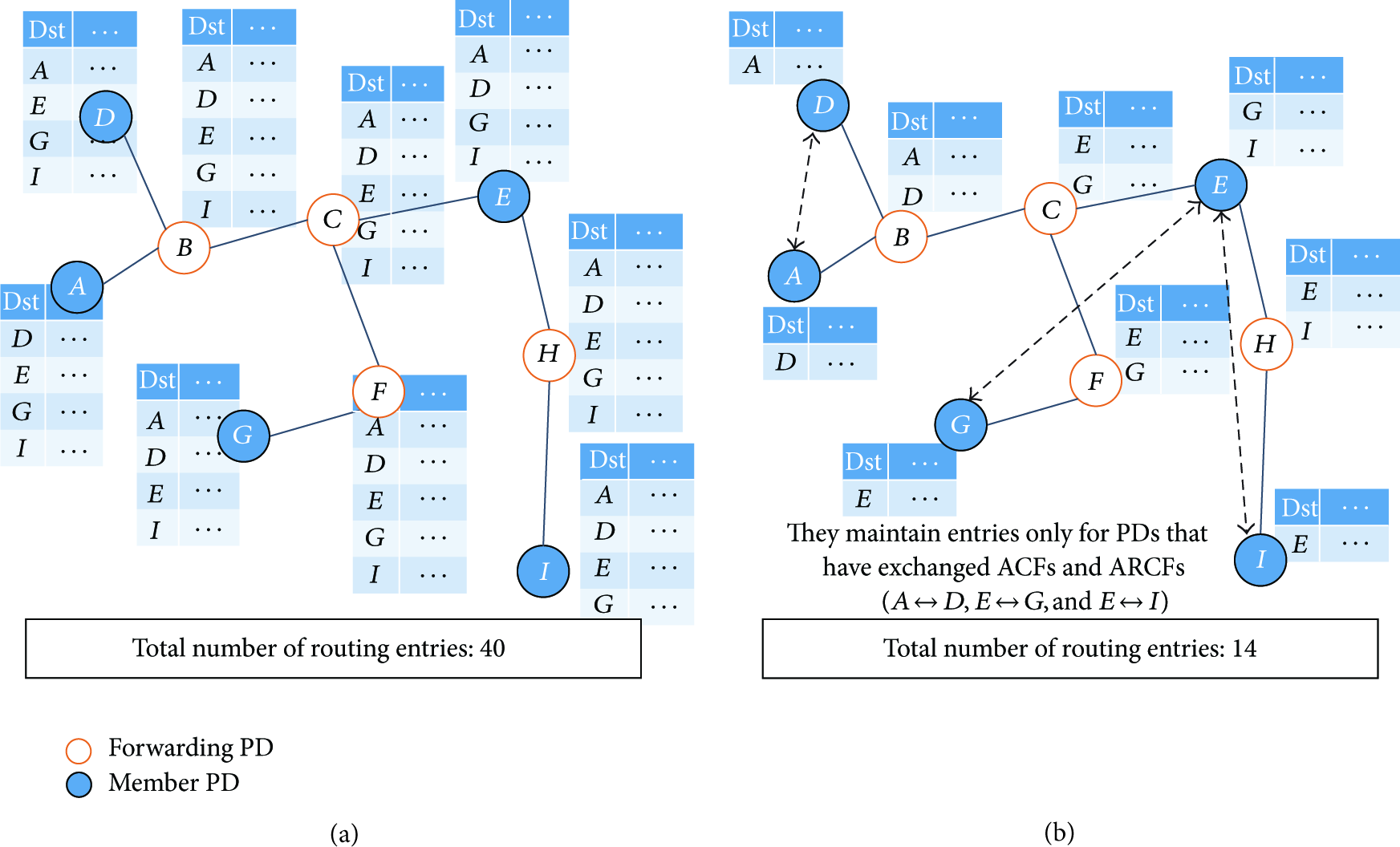
The comparison between heavy-weight routing table and light-weight routing table.
3.2.2. Device Group ID Creation
A multicast group is determined by
3.3. Multicast Group Notification Frame (MGNF)
The purposes of MGNF are (1) limiting duplicate ARCFs, (2) managing the routing table, (3) leaving notification to multicast group, (4) device group ID creation, (5) request for unicast routing, (6) reply for unicast routing, (7) mobility support, (8) local repairs, and (9) notification of removed routing entries. These are listed in Table 2.
Type of multicast group notification frame (MGNF).

3.3.1. Limiting Duplicate ARCFs
A PD receiving an ACF multicasts an MGNF with notification type set to
3.3.2. Management of Routing Table
In order to reduce entries in the routing table, each PD maintains entries only for PDs that have exchanged ACFs and ARCFs in their routing tables. Each PD in a multicast group multicasts MGNFs periodically such as (
3.3.3. Leaving Notification to Multicast Group
There are several reasons for a PD to leave the network: (i) by its intention, (ii) by mobility, and (iii) by limited resources. If a PD wants to leave from a multicast group, it multicasts (within K-hops) a MGNF with notification type set to 2. Upon receiving the MGNF, a forwarding PD deletes the entry of the originator of the MGNF and forwards it. On the other hand, the nonforwarding PD does not forward the MGNF.
3.3.4. Device Group ID Unification
When two or more multicast groups or nodes are merged, the device group ID should be identical. The PD that recognizes the existence of two or more multicast groups determines the device group ID for those groups randomly. Then, the PD sends MGNF (notification type: 3 and TTL: ∞) to the group that does not have the selected group ID to update the multicast group ID.
3.3.5. Requests for Unicast Routing
When a PD wants to unicast data frame, the PD searches routing entry of destination address in its routing table. If the PD finds the routing entry of destination address, it starts to unicast immediately. If it does not find routing entry of destination address, it multicasts a MGNF (notification type: 4) to group.
3.3.6. Reply for Unicast Routing
When the other PD receives the MGNF (notification type: 4), it saves backward route information in its routing table. Then, it starts to find a routing entry of destination address in its routing table. If a PD receiving MGNF finds routing entry of destination address, it unicasts a MGNF (notification type: 5) to the PD which wants to unicast.
3.3.7. Mobility Support
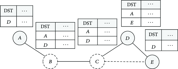
When a node moves within the one-hop coverage of another node, both of the nodes are aware of each other within the one-hop by TTL of MGNFs and they update their routing table. Then one of them sends a MGNF (notification type: 6) to another neighbor node. Therefore, the notifying node becomes aware that the nodes became closer. However, if the node is a multicast group member, it does not do anything. If it is a forwarding PD, it deletes the routing entry whose destination field is for both of those nodes. Assume the topology that Figure 3(a). If C moves near to A (Figure 3(b)), A and C recognize each other because A directly listen to C's MGNF frame. When C recognizes A, C unicasts a MGNF to B to notice that A and C become neighbor to each other. Then, B deletes routing entries of A and C.

An example of mobility support (all nodes A, B, and C are separated by 1-hop).
3.3.8. Local Repair
Since an expiration timer is proportional to the number of hops from the impaired PD, the closest multicast group member detects link breakage. A PD starts local repair if it detects link breakage between multicast group members. Then, the PD multicasts a MGNF (notification type: 7). If PDs receiving the MGNF do not have an existing routing entry for originator of the MGNF, a routing entry is created and an expiration timer
3.3.9. Notification of Removed Routing Entry
When routing table of a node is full of routing entries, it chooses another node from its routing table with shortest distance (hop-based) firstly. It sends a MGNF (notification type: 8) to the chosen node and sets timer. When the node receives the MGNF, it breaks the link between the node and itself and sends an ACF. The node which has timer ignores the ACF and another node which receives the ACF sends an ARCF to it and creates a new link between the node which sends the ACF and itself.
3.4. Creation and Management of Routing Table
3.4.1. Creation of Routing Table
Whenever a relay-enabled PD receives an ACF or an ARCF, a routing entry is created in the routing table. Also, the routing table is updated by a receiving MGNF. A routing table contains a destination address, next-hop address, expiration timer, number of hops, current sequence number (current_SN), device group ID, and last ACF reception time (
3.4.2. Management of Routing Table
Since MGNF (notification type: 1) is sent periodically, a MGNF implosion problem can occur in the network. To prevent this problem, we propose an adaptive MGNF transmission technique based on the distance between nodes. The distance can be measured from the received signal strength indicator (RSSI). This technique is used when the distance between nodes becomes longer or shorter. If the node moves away from the network, the MGNF transmissions become more frequent since there can be a link breakage. In contrast, if the node moves within one-hop coverage (e.g., mobility support), the MGNF transmissions become less to prevent redundant MGNF traffic.
3.4.3. Merging Multicast Groups
The finding/joining procedure using ACFs and ARCFs can help to merge disjoint groups. If a PD in a group receives an ACF from different disjoint groups with the same
3.5. Multicast Data Transmission
If a PD receives a multicast data frame, it has to decide whether to forward the frame or not. The PD receiving the multicast data frame compares the source address of the data frame and next-hop address entries of its routing table. The PD checks the next-hop addresses in its routing table. If it finds one or more next-hop entries which do not overlap with the source address of the received frame and those next-hop entries have the same device group ID as the received frame, then, the PD forwards the incoming data frame to other PDs. Otherwise, the PD does not forward the incoming frame. For the multicast data transmission, we have to know the destination address, source address, originator address, sequence number, and TTL from the multicast data frame. This information should be included in all multicast data frames. In Figure 4, there are five nodes in the topology. A, D, and E are in the same group; B and C are a forwarding PD. Although C and E are in one-hop range, routing table creation policy of the FDMRP does not make cyclic links. If A sends multicast data, B compares source address and routing table. Since B has one next-hop entry which is not overlapped with A, B forwards the data. In the same way, C and D also forward the data. Then, a group including A successfully receives the multicast data from A.
The routing table of the FDMRP.
3.6. Prevention Loopback Problem
PDs can prevent multicast/broadcast loopback problems by using the sequence number (SN) of data frames. When a PD forwards data with SN = n, the PD sets the current_SN field in its routing table to n. If the receiving frames SN is not greater than the current_SN, the PD discards the frame.
4. Theoretical Analysis of FDMRP
As mentioned earlier, the ARCF is delivered by a PD who transmits a MGNF (type: 0). However, in the special topology, this procedure causes overheads as in Figure 5. We can observe that multicast creation overheads of Figure 5(a) are less than those of Figure 5(b). To resolve this problem, PDs have to negotiate other PDs to decide a PD that will send ARCF to a PD sending ACF. The negotiation process is initiated by the PD who receives an ACF. The MGNF for negotiation contains the number of routing entries. If a PD receives an ACF, the PD multicasts MGNF with the number of routing entries of the PD. When transmission of MGNFs is finished, the PD which has the largest number of entries replies with an ARCF to the PD sending ACF.

(a) Multicast is done with 1 transmission; (b) multicast is done with 4 transmissions.
Although multicast transmission has advantage, negotiation based joining scheme has a lot of overheads for joining process. This is because all PDs receiving ACF have to multicast MGNFs. To determine appropriate joining scheme, we analyze the control overhead of joining procedure and multicast.
4.1. Success Probability of CSMA in Multihop Networks
The success probability of transmission depends on neighboring PDs. Therefore, the precise computation of the probability is difficult. We use the Markov model to evaluate the average success probability of a transmission. In each slot, a nontransmitting PD may become ready to transmit with probability p. When a PD senses the channel is idle, the PD transmits its frame. We assume that, in each slot, a nontransmitting PD transmits a frame with probability
To determine a probability of the channel which is sensed to be idle in a slot, we design the channel process by a two-state Markov chain shown in Figure 6. According to the system model in Section 3.1, the probability that there are i PDs in a disc area where radius is R is given by

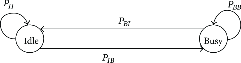
The Markov chain for a channel.
Therefore, the transition probability that channel remains idle, denoted by 
Denote the steady-state probability of Idle and Busy states as 
The limiting probability 
From (4), the transmission rate 
Now, we determine the probability of a successful transmission from PD in a slot. The transmission stages of PD can be represented by a Markov chain which is shown in Figure 7. The Markov chain consists of three states: the Idle state, the Successful transmission state, and the Collision state. At the beginning of a slot, if a PD is in the Idle state, it leaves Idle state with probability 

The Markov chain for a PD x.
We can determine the transition probability 


Since the PDs are uniformly distributed in region 
Therefore, the transition probability 
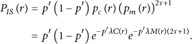
Finally, from Figure 7, the steady-state probability of state S can be expressed as
4.2. Joining Overhead
In non-negotiation-based joining scheme, the joining overhead 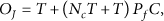

In Figure 8, we compare
The joining overhead versus the number of nodes in the entire network.
4.3. Multicasting Overhead
In this subsection, we evaluate the multicasting overhead with mobility. The multicasting overhead is correlated with the number of the forwarding data and the number of the rejoining data frames (local repair) by mobility. First, the overhead with one multicast data 


Figure 9 shows the multicasting overhead per δ. We assume the parameters

The multicasting overhead versus the number of nodes in the entire network.
Through theoretical approach to get a joining overhead and a multicasting overhead, we can decide which approach is appropriate for the network environment.
5. Performance Evaluation
In this section, we evaluate the performance of the proposed protocol compared with the ODMRP [16] and path-aggregation-tree multicast routing scheme (PAT) [22]. For performance evaluation, we use the OPNET modeler [27] and we measure the number of routing entries, control overhead, joining latency, and areal sum goodput during a 1 hour simulation time. In the simulation, we form a two-step uniform random drop model where the nodes are located within 500 m of each other. MAC and PHY layer system models follow the TG8 technical guidance document [28]. The simulation parameters are listed in Table 3.
Simulation parameters.
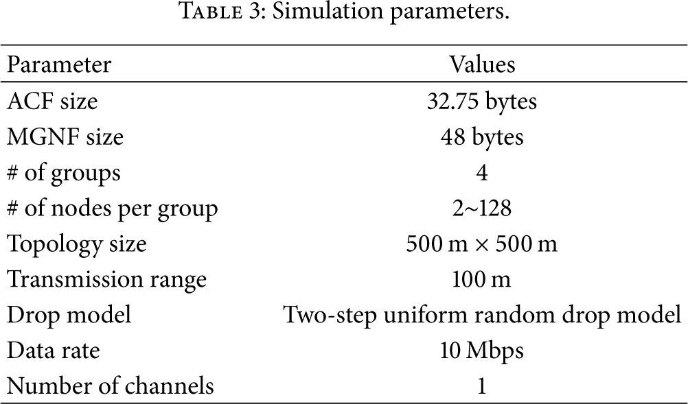
Figure 10 shows the control frame overhead versus the number of nodes. In the figure, control overhead of the FDMRP is lower than the ODMRP and PAT. This is because in the ODMRP the join request message floods frequently and periodically for managing the multicast group. Also, when a PD receives join request message, it continuously relays to its neighboring nodes until maximum TTL is reached. In the PAT scheme, since they try to maintain multiple trees for transmission, the control overhead increases as the number of nodes increases. Additionally, when a new node joins a multicast group, all nodes should reconstruct all of multicast trees. As a result, it causes significant control overhead. On the other hand, in the FDMRP, ACF flooding does not occur because when a node replies with ARCF, the ACF does not flood because a node sending the ACF is already joined to the same group as the node sending the ARCF.
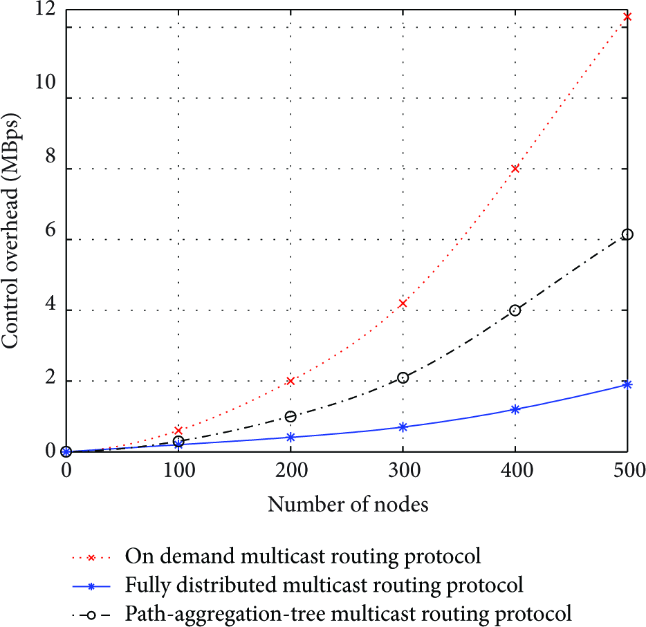
Control frame overhead versus # of nodes.
Figure 11 shows the number of routing table entries versus the number of nodes. From the figure, we observe that the number of routing table entries of the FDMRP is lower than other schemes. This is because both of the schemes store an amount of information for neighbor nodes and routing information for nodes within a multicast group. Particularly, the number of entries significantly increases as the number of nodes increases for ODMRP scheme because all of nodes maintain routing entries for all of destinations. However, the FDMRP stores minimum information for routing. That means the FDMRP can perform multicast routing with few routing table entries than the other schemes.
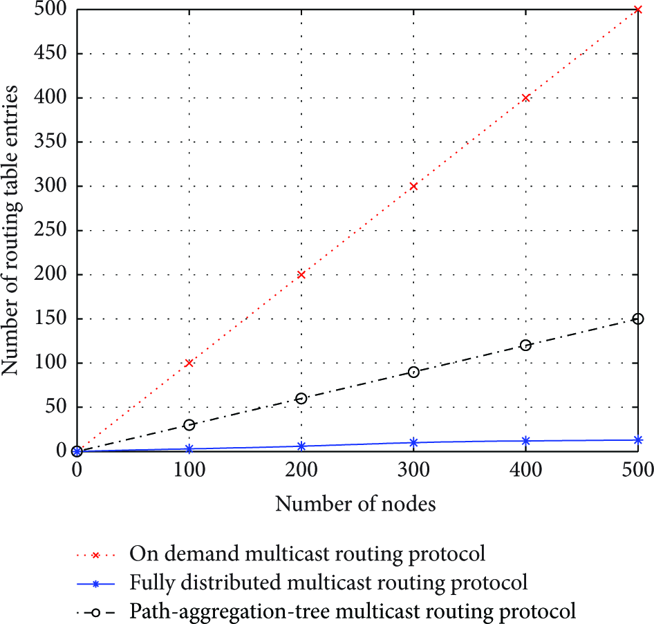
# of routing entries per node versus # of nodes.
Figure 12 shows the time of joining latency versus the number of nodes. In the figure, joining latency of the FDMRP is significantly lower than the other schemes. Since a node which uses the other schemes has to communicate with each receiver in a multicast group, the joining latency is higher in a large network. Particularly, if a receiver is far away from the sender node, joining latency also increases. However, in the FDMRP, a node can join a multicast group when there is at least one peer node in proximity to the node.

Joining latency versus # of nodes.
Figure 13 shows the areal sum goodput versus the number of nodes. The areal sum goodput is calculated by throughput of all nodes and area of topology. In the figure, goodput of the FDMRP is lower than the other schemes when a low number of nodes are located. Otherwise, goodput of the FDMRP is higher than the other schemes. This is because the other schemes have control messages with broadcasting while the FDMRP has multicasted one. Although the FDMRP performs more forwarding than the other schemes, the control packet overhead is a another serious factor in throughput. The result shows that the FDMRP is suitable with large scale network.

Areal sum goodput versus # of nodes.
In these figures, we observed that a control overhead, routing entries per node, joining latency of the FDMRP are extremely lower than the existing schemes. Although the number of routing tables is less than the existing scheme, the FDMRP shows significant throughput in the large scale network. If the network scale becomes larger, the difference of performance also becomes larger.
6. Conclusion
In this paper, we addressed the problem of coordination of a multicast group. Also we addressed the number of routing table entries and time cost for a joining procedure. Existing MANET multicast routing protocols cannot properly resolve the above problems and do not cope with environments which numerous nodes. To solve these problems, we proposed the fully distributed multicast routing protocol for PAC networks. FDMRP exploits the group joining scheme to minimize routing table entries. To minimize routing table entries and reduce join latency, replies to the join message are sent by only one node in each group. To reduce control overhead, group management messages are transmitted to nodes in the routing table. The simulation result shows that our protocol is very effective for reducing control overhead and provides minimized routing table entries. Furthermore, our protocol provides reduced group joining latency compared with existing protocols. As future work, some problems such as reliability in high density environments should be investigated. Enhanced reliability ought to be considered to improve routing efficiency.
Footnotes
Disclosure
Part of this work was presented at ICOIN 2014.
Conflict of Interests
The authors declare that there is no conflict of interests regarding the publication of this paper.
Acknowledgments
This research was supported by the Chung-Ang University Excellent Student Scholarship and National Research Foundation of Korea (NRF) funded by the Ministry of Education (NRF-2013R1A1A2012443).