
Abstract
We propose decoupling energy and sensing planes in WSN. This decoupling represents a paradigm shift as it can alleviate the fundamental problem of energy depletion in WSN and can (in theory) offer a sensor network with infinite lifetime. We present energy transference as the mode of decoupling energy by allowing energy to move between energy-rich and energy-poor nodes. We present a first practical energy distribution architecture that allows us to decouple energy supply from sensing activities. Such a separation of responsibilities enables us to utilize abundant energy sources distant from the sensing location, allowing unrestricted lifetime and resolving unequal energy consumption in WSN. We demonstrate energy transfer for practical decoupling using low-cost and low-footprint, laser μ-power beaming that powers current WSN platforms at 100 m of range. We design and implement LAMP, a tiered architecture to manage energy supply to both mesh and clustered WSN deployments using an energy distribution protocol. We evaluate our system to show that, for an additional cost of $29 per mote, LAMP can support perpetual mesh functionality for up to 40 sensors or 120 nodes in clustered operation.
1. Introduction
It is revealing to observe that the vast majority of research in the WSN community has focused on efficient energy management, albeit the principle motivation of WSN is to provide in situ sensing capability. This research bias is due to a fundamental coupling of the energy sources and their distribution (energy plane), with the spatiotemporal sensing requirements (sensing plane) of an application. This coupling, in turn, is necessitated by the axiom that availability of energy (wall socket or ambient) is independent of the sensing location.
There are two limitations arising from this coupling of a limited energy resource to a sensing location. First, it precludes the use of an abundant and cheap energy source physically distant from the sensor. A resulting trade-off occurs between sensing fidelity and greater lifetime achieved by using the large potpourri of energy management techniques developed by the research community [1–6]. Figure 1(a) shows an example of body sensor network where a wireless energy solution can simply use wall power to indefinitely run all sensors. While wireless energy might be inefficient, any cost of grid power wasted when weighed against the benefit of removing lifetime related constraints on sensing or communication is, in our opinion, quite acceptable.

Existing WSN deployments. The potential for wireless energy transfer is restricted due to coupled energy and sensing planes.
A second limitation, due to varying energy consumption across a WSN, results in nonuniform energy resource depletion. Such a scenario can result in a nonfunctional WSN even when the global (across the deployment area) energy available is sufficient for its operation. While harvesting energy at sensor node mitigates some of these limitations, the independence of ambient energy from sensor placement still results in a similar conundrum. Figures 1(b) and 1(c) show two such real WSN deployments by ETH-Zurich at Matterhorn and USC/ISI in a Costa Rican rainforest. In both deployments we see excess energy in areas with sunlight (one side of a ridge and the forest canopy) but they are forced to use batteries as all locations are not equally provisioned. As a result, despite using state-of-the-art energy efficient mechanisms for extending lifetimes, both deployments need frequent and difficult battery replacement.
We propose decoupling energy and sensing planes in WSN. This is enabled by the wireless energy research [7, 8] that removes the requirement for the energy source to be on or near the sensor node. By decoupling energy and sensing planes we can (i) treat energy as an independent, deployment wide shareable resource, (ii) create an abstraction of the energy plane that the sensing plane can use, for example, to request distribution of energy to satisfy sensing requirements, and, (iii) alongside existing energy management techniques, allow energy generation and distribution to evolve independently of the sensing requirements of an application.
We first identify four requirements for a wireless technology to practically enable decoupling in WSN. Any technology must be wireless with small footprint, have low cost, provide energy at radio comparable range, and deliver enough energy to support existing mote-class devices such as TelosB. To this end, we build the first practical, laser-basedμ-power beaming mechanism that meets these requirements by recharging a depleting node at an order of magnitude higher scale (mWs versus μWs), that too at an order of magnitude greater range (100 m versus 2-3 m) than existing mechanisms (Section 3).
We then design LAMP, an architecture that decouples energy and sensing planes in WSN using laser μ-power beaming (Section 4). LAMP is based on a tiered energy plane that distributes energy from power unconstrained (e.g., via wall sockets) master nodes to leaves that perform in situ sensing. Thus, LAMP enables the use of an abundant and cheap energy source physically distant from the sensor and schedule energy supply to match unequal consumption. We design LAMP to support any implementation of the sensing plane: from full mesh operation with homogeneous sensors to the tiered operation with specialized routing and sensing nodes commonly used for practical WSN deployments [9, 10].
We then build a prototype of our energy distribution architecture, delineating the practical limits of energy demand it can support for existing sensing architectures. We answer questions regarding its accuracy, scalability, and supported data rate (Section 6). We thus identify the need for laser recalibration at leaf distances greater than 29.5 m and a minimum spacing of 0.8 m between leaves for power beaming at 100 m. We show that our implementation can support TelosB class of motes with 7.4% duty cycle at distances in excess of 100 m. Furthermore, our system can perpetually support up to 120 leaves per master in clustered mode (only master-leaf communication) and up to 40 leaves in mesh mode (unrestricted intraleaf communication).
Our work thus has the following four contributions:
We identify essential constraints for practical energy transfer in WSN and build a laser power beaming solution that meets them. We design the first energy distribution architecture providing an energy plane abstraction to any sensing application in both mesh and cluster WSN deployments. Based on this architecture, we develop an energy plane control protocol to manage energy distribution across deployment and energize sensor nodes. We implement a prototype of this architecture and the control protocol to thoroughly evaluate and understand its practical limitations and scope.
2. The Argument for Decoupling Energy and Sensing Planes
We now elaborate on the concept of energy and sensing plane abstraction for a general WSN deployment (Figure 2). We use these abstractions in our paper to later understand the LAMP architecture.
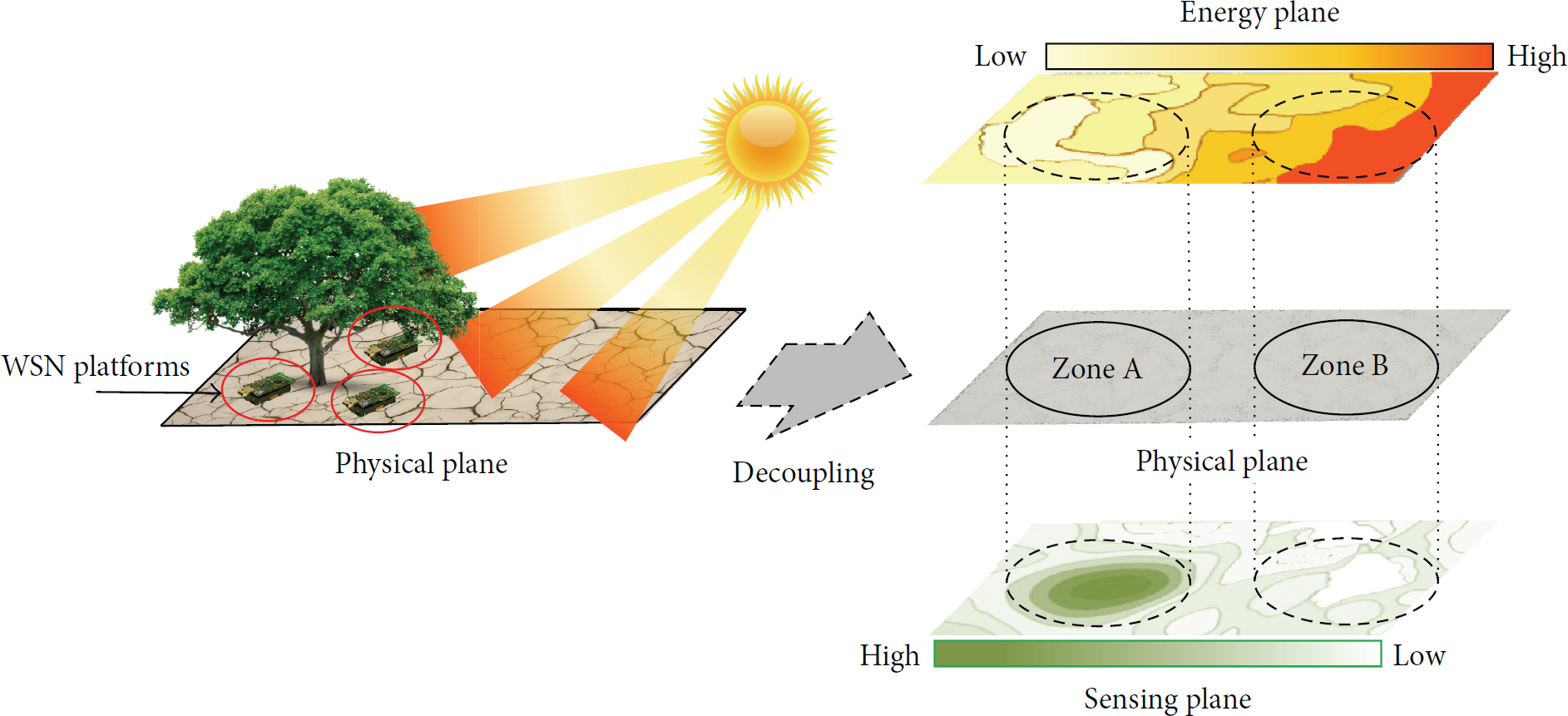
Decoupled energy and sensing planes in WSN. These planes are spatially uncorrelated in most deployments.
2.1. The Energy and Sensing Planes
The energy plane (E-plane) represents the distribution of energy sources, such as batteries, wall sockets, or ambient energy. The sensing plane (S-plane) represents the distribution of application-specific sensory information. Ideally, a WSN application wants to optimize deployment—in terms of cost, lifetime, and fidelity—for data sensing with just the S-plane information. However, these two planes do not overlap in most deployments; that is, an energy-rich area may not be a sensing point of interest. (Energy harvesting is beneficial only in areas where these planes serendipitously overlap.) This is why current WSN deployments couple these planes by adding energy sources (using batteries) at the sensing location.
As a consequence of the above coupling and the resulting paucity of energy at each node, WSN research has been focused on energy-conscious design, with many novel energy management techniques being proposed in the last decade. However, all energy management techniques implicitly trade off continuous and high fidelity sensing for greater lifetime. This coupling fundamentally limits energy at sensor nodes due to three application-specific constraints. First, in situ sensing must be done where the application requires it, but these locations are spatially uncorrelated with nearby and abundant energy sources (like sunlight or wall socket). Second, both sensor nodes and their harvesting mechanisms have size limitations to minimize invasiveness of the WSN application (e.g., surveillance or habitat-monitoring). Finally, postdeployment energy consumption varies for nodes with time and usage, causing an unequal distribution of energy at each node.
If we decouple these two planes, we can design a separate architecture that abstracts the transport of energy between locations in the E-plane. We can now, with this abstraction, remove the above limitations in one of two ways: either use it to balance unequal energy distribution in WSN by taking from energy-rich nodes and giving to energy-poor nodes, that is, a modified Robin Hood argument. Alternatively, we no longer compromise on the functionality or fidelity of a sensing application just to increase lifetime as energy can now be provided, within reasonable limits, on demand from a location with abundant energy (like a wall socket).
A pertinent analogy, and a motivation to decouple energy generation from its use, is the power grid which implements such decoupling, thereby allowing both consumer applications (e.g., home appliances) and energy distribution technology to evolve independently and more efficiently.
2.2. Benefits of Decoupling Energy and Sensing
In this paper, we advocate a cleaner and explicit understanding of the spatial decoupling between E-planes and S-planes. We believe that this separation provides four benefits. First, in a decoupled sensor network, new energy management techniques can be explored by sharing energy across a deployment. Second, a decoupled view will allow efficient sensing to evolve independently from energy generation and sharing. Third, an explicit understanding of the decoupling will allow the deployment engineer to make an informed choice between a coupled (existing) or decoupled deployment. Finally, we believe that all existing approaches in energy management are complimentary to any new solution, hence strictly improving the viability of existing WSN research.
With the above motivation in place, an obvious caveat is the cost of implementing energy-sensing decoupling in practical WSN. This decoupling can be realized only if it is cost-effective to move energy between nodes. We show in Section 3 that required technologies exist and, driven by consumer demand and rapid commoditization, will allow cost-effective decoupling.
2.3. Scenarios Benefiting from Decoupling
Figure 1 shows motivational examples of current WSN deployments where energy-sensing decoupling is necessary. One of the deployments (cf. Figure 1(b)) is for permafrost monitoring on the Matterhorn in Switzerland [14]. The deployment has a base station energized through solar panels; however, all permafrost sensing nodes cannot be solar powered as nodes on the north side of the same ridge are never exposed to sunlight during winters. Today, they power all sensors with batteries that require regular replacement. An energy decoupled view here would show excess energy at nodes not on the north facing sides and a deficiency for nodes on the north side. Thus, a solution that can share energy between these two zones will prevent the need for manual and arduous battery replacement.
A second forested deployment was done by USC/ISI in Costa Rica (cf. Figure 1(c)). In this deployment some sensors were placed in the tree canopy, with plentiful solar power, while sensors in the understory remained energy impoverished. Even for nodes deployed within the understory, the sunflecks distribute sunlight unevenly and cannot provide a dependable energy source. Again, a decoupled view would consider placing a large solar harvesting mechanism in the canopy with some sharing mechanism to the nodes down below.
Potential Scenarios. Apart from the general WSN deployment scenarios cited above, we further present two current areas of WSN research that can benefit tremendously from a decoupled view. First is the research for on-body sensor networks. Here, we can deploy more capable, less-energy constrained, on-body systems that, beyond data logging, identify health emergencies using algorithms currently offloaded to a gateway. A decoupled system will allow us to transport energy from elements that are grid-powered. A second area is ecological observation of animals. For animals that forage and return to their nesting place every night, a decoupled view allows a bulkier energy harvesting system near the nesting location. Then, when the animals return at night, this system can transfer accumulated energy to the tags/sensor on them. These sensors can in turn now perform greater functions (using GPS, wifi, etc.) as the requirement to hold charge is brought down from year(s) to just one day.
3. Energy Transfer for WSN Using Laser μ-Power Beaming
Several recent works propose interesting mechanisms for energy transfer within the context of WSN deployments [8, 15–20]. However, we believe that each of these mechanisms lacks some critical aspect, which makes them unsuitable for the majority of practical WSN scenarios. We first identify these minimum requirements for a WSN-specific energy transfer mechanism and then evaluate laser-based μ-power beaming as a suitable option.
3.1. Practical Constraints for Energy Transfer in WSN
At the minimum, a practical solution for energy transfer should not violate the fundamental goals of cheap, in situ, collaborative, and long lived sensing for WSNs. We thus believe that a WSN-specific energy transfer mechanism should have the following properties: (1) it should have small size and be wireless to allow minimally invasive deployments, (2) it should be a low-cost solution (sub-$100), (3) it should provide sufficient energy (in 10 s of mW) to power typical WSN class devices for sensing and communication purposes, (4) finally, its range of energy transfer should be at least comparable to typical communication range (10 s of m; direct or by routing) of WSN nodes to allow reasonable density of deployment.
We acknowledge that there can be other constraints that are specific to an application, like safety, line-of-sight, and directionality. However, the above are minimum requirements for integration with any practical WSN application.
3.2. Sensors with Lasers
We propose using laser μ-power beaming as an appropriate mechanism for WSN as it fulfills the above requirements. Our choice of laser μ-power beaming is inspired by higher-density power beaming research for satellites and UAVs [21, 22]. However, in order to meet the cost and size constraints, we radically reduce the scope of our power beaming solution.
We next discuss our setup to evaluate the range and energy transfer capability of such a system. We also experimentally compare our approach with two other approaches for energy transfer proposed earlier: light-based [8, 16] and RF-based [18, 20].
3.2.1. Evaluation Setup
We use three different mechanisms for energy transmission in the context of WSNs (Figure 3). For RF power transfer we use Powercast's module (same as in [20]) that uses a 3 W transmitter [23]. We use a 3 W Cree Q3 LED torch for energy transfer using light [24]. Finally, for our laser power beaming we use a 808 nm 0.8 W near-infrared laser module with adjustable beam width [25]. This laser has a driver circuitry to adjust its output power (for safety concerns).
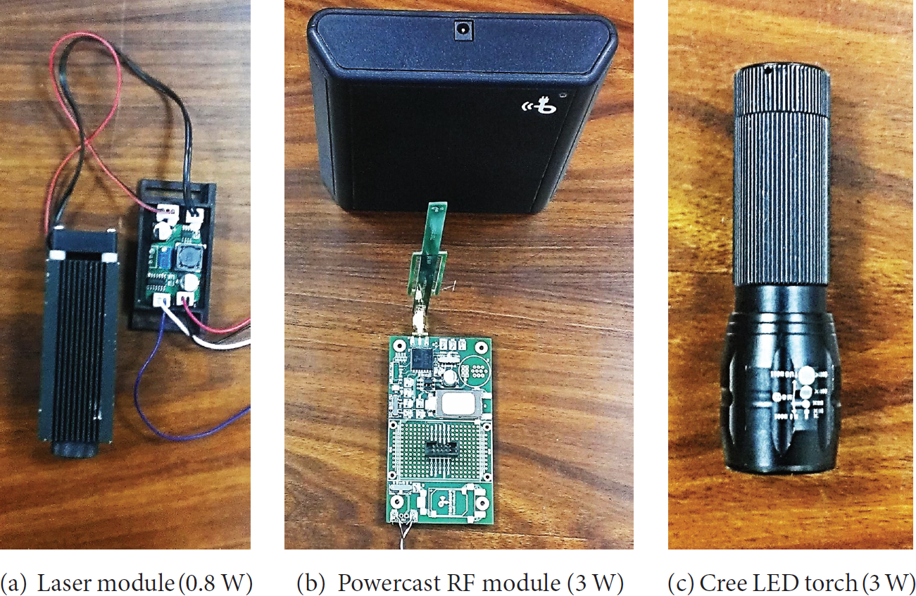
Wireless energy technologies.
We use a monocrystalline, high-efficiency solar cell [26] to collect radiant energy transmitted by both laser and LED. This solar cell has high efficiency (≈20%) with good response for frequencies of both visible and laser light. Additionally with its small size (
We use a simple setup with the transmitter and receivers perfectly aligned to measure the amount of energy received at different range. For each experiment, we optimally tweak the load at the receiver for fair comparison, as the actual amount of energy harvested depends on the load. Figure 4 shows the result of all the three mechanisms, which we next use to justify the selection of laser power beaming.

Harvested power at different ranges (log scale). Also shown are power requirement for TelosB operation at different duty cycles.
3.2.2. Range of Power Transfer
The first conclusion we can draw from Figure 4 is that laser power beaming is the only mechanism that can provide consistently good energy transfer at the 80–100 m range expected of current WSN nodes (requirement (4)). Thus, while both the RF and light-based transmitters use greater power (3 W), they effectively are unable to transfer energy beyond a couple of meters. Laser μ-power beaming, on the other hand, consistently provides around 7 mW of power all through 10–100 m of range. We observe a decrease in laser power transfer at less than 10 m due to the laser beam not covering the entire solar panel at these short distances. This limitation, however, is technological; optics in front of the laser can be used to spread the laser beam and cover the entire panel.
3.2.3. Supported Class of WSN Applications
We now evaluate the class of devices or application that each transfer mechanism can support, at their best operating point, where we normalize the power delivery different ranges. For this purpose we use a simple method where Figure 4 shows three average power requirements for a TelosB mote-class device under different duty cycles. These lines can be viewed to signify either different application requirements or a different class of devices [27, 28].
We again observe that only laser μ-power beaming can support typical WSN application and devices (requirement (2)). We, therefore, do not require a trade-off for lower capability platforms (like CRFID or EnHANTs [28]) which constrain the WSN applications we can support. Thus, all current WSN applications can simply focus on meeting the sensing requirements and request energy from our energy distribution system. Furthermore, laser μ-power beaming can support these devices even at 100 m as its coherent nature results in little loss in power transfer over longer range.
3.2.4. Cost and Conclusion
We now evaluate the cost of deploying these solutions on a single pair of devices (to transmit and receive power). Table 1 shows the cost comparison for deploying the four technologies. We note that laser μ-power beaming is slightly more expensive than simple light based energy transfer. However, this extra cost becomes negligible when amortized over the 120 nodes we can support (see Section 6.4).
Comparing wireless energy schemes.
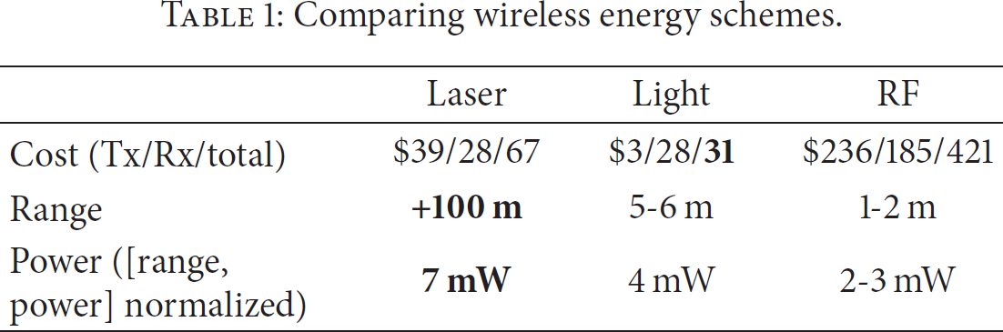
We thus conclude that laser μ-power beaming is the most suitable energy transfer mechanism among those available that satisfy requirement (1).
4. LAMP: Energy Distribution Architecture
We now present LAMP, a WSN architecture that allows us to decouple the E-plane, using our laser μ-power beaming mechanism, and transport energy to meet WSN requirements in the S-plane (cf. Section 2).
4.1. A Heterogeneous and Tiered Energy Distribution Architecture
We design a two-tier architecture for energy transport within a WSN, using a heterogeneous deployment which separates the roles of nodes responsible for sensing from the nodes responsible for energy generation and its distribution.
A homogeneous architecture would imply nodes to be equally capable of sensing, networking, harvesting, and energy transport. However, questions about the practicality of such an architecture, applicable even more for energy transport, have repeatedly been raised [10, 29–31]. A heterogeneous energy distribution architecture, in our opinion, is more promising. This is mainly because it allows us to clearly separate nodes responsible for generating energy from the nodes that consume energy in the E-plane and sense in the S-plane. With the help of wireless energy transfer between these nodes, we can then support the desired interaction between E-plane and S-plane abstractions to satisfy application sensing requirements. This architecture is similar to the recently proposed [9, 10] tiered architectures for WSN.
LAMP is thus based on a two-tier architecture represented by a master and its leaves. As shown in Figure 5, we propose LAMP masters as being responsible for energy generation and its distribution to the leaves in the E-plane. These leaves are WSN nodes responsible for sensing. (Note that this overlap between E-plane and S-plane functionality at the leaves is essential.) A master is unconstrained in that it is engineered with an abundant supply of energy, whereas a leaf is responsible for receiving that energy in the E-plane and sensing and reporting, at the location of interest, in the S-plane. The use of laser μ-power beaming, because of its longer energy transfer range, allows a relatively unconstrained, spatial deployment of leaves. The master periodically recharges and samples each assigned leaf to achieve the desired goals of a deployment.

LAMP architecture.
We emphasize that this tiering is employed to assign a set of leaves to each master in the E-plane. It does not restrict leaves from communicating with each other or with a sink node, possibly over multiple leaf hops in the S-plane. We defer a detailed discussion on possible operational modes of LAMP to Section 4.2.
Discussion. This architectural separation of node duties in LAMP is not new: it is similar to other tiered architectures in the S-plane, such as Tenet [29], consisting of constrained motes in the lower tier and relatively unconstrained masters in the upper tier. Tenet introduces this architectural separation to increase network capacity (i.e., using masters) while constraining motes to only minimally process locally generated data. While promoting Tenet motives, LAMP (we do not use the programming model of TENET but only borrow the architectural separation of node duties in WSN) assigns masters an additional role, in the E-plane, of generating energy and disseminating it to a set of leaves placed in situ.
The use of this tiered architecture for LAMP is intentional as it has been repeatedly advocated by WSN pioneers both in the past [32] and of late [10]. Hence, our choice is based on this strong observation that the future WSN deployments will be tiered [10, 29–31, 33] especially with the recent surge of the idea that Internet protocols should be applied even to the smallest devices [34]. In fact, this tiered networking architecture is not even idiosyncratic to WSN; it has been in use for long in pervasive identification systems, such as RFID, which uses a powerful reader to send signals to powerless tags within communication range to read their response. Hence, the use of this tiered architecture extends the utility of LAMP beyond the spectrum of typical WSN applications, for example, to improve the computational capacity and transmission range of RFID and Computational-RFID (CRFID) systems.
4.2. LAMP Operational Modes
Before presenting the implementation details of LAMP and its energy distribution mechanism, we first briefly discuss the operational modes supported by LAMP in terms of how the communication takes place in such a tiered WSN architecture. LAMP supports two operational modes, that is, mesh and cluster, to establish a multihop WSN. These two modes offer different advantages while imposing restrictions on performance characteristics such as recharging rate and the number of leaves per master (i.e., scalability).
4.2.1. Mesh Mode
This mode provides full mesh functionality in that it allows interleaf communication (cf. Figure 6(a)). Thus, leaves directly communicate with each other by using the extra amount of energy stored during a charging epoch. This mode is similar to the ad hoc mode in IEEE 802.11. The principle advantage of this mode is that it enables LAMP to support existing WSN applications and protocols that assume mesh connectivity. However, with the radio being used more frequently, this mode is less scalable in terms of the number of leaves per master.

LAMP operational modes.
4.2.2. Cluster Mode
In cluster mode, leaves only communicate with each other through their respective masters (cf. Figure 6(b)). Thus, while we assume that these nodes will sense at some application defined sampling rate, their radio will remain off until activated by the master through a charging epoch. This mode is similar to the infrastructure mode in IEEE 802.11, where the hosts can only interact through their access point. The principal advantage of this operation mode is that it improves scalability of LAMP (cf. Section 6.4). This improvement is because a leaf can live longer since its radio remains off once the interaction with master is over, allowing the master to supply a denser WSN that senses perpetually. However, the major drawback of this operational mode is that it requires changes in the existing application and protocol architectures developed for WSN.
We note that in both operational modes scalability is only limited if we want a perpetually active network where all the leaves are recharged before their power levels drop below their operational threshold. Otherwise, the scalability of both these modes is only affected by application constraints such as the desired recharging rates and data rates. We provide a detailed qualitative analysis for these different operational modes in Section 6.4.
4.3. Implementation of the LAMP
After describing the different operational modes of LAMP, we now discuss the implementation details and roles of LAMP master and leaves.
4.3.1. LAMP Master
A master is responsible for three functions: energy transmission, scheduling and directing energy at the appropriate leaf, and exchanging data with leaves.
Figure 7(a) shows our implementation of a LAMP master. We use laser μ-power beaming mechanism (Section 3.2) to provide the energy transmission capability. We develop a dual-axis, pan-tilt mechanism using servomotors with 180° rotation possible in both axes. The laser module mounted on this platform is controlled through a TelosB mote. LAMP protocols can use this apparatus to localize and focus the laser beam on the desired leaf. Finally, the master uses the TelosB radio for data communication with leaves. In our current implementation, master node is supplied with abundant energy without any constraint; that is, laser module is powered through power socket.

LAMP system components.
4.3.2. LAMP Leaf
A leaf is required to possess two basic capabilities: the ability to receive energy and the ability to communicate with the master and other leaves.
Our LAMP leaf is a TelosB (Figure 7(b)), without batteries, equipped with a monocrystalline solar panel (same as in Section 3.2). This panel converts energy of a focused laser beam in order to power a TelosB. We also attach a capacitor between the solar panel and the TelosB's input to allow energy buffering, thus enabling duty cycled operation. If required, rechargeable batteries can also be attached to the TelosB and charged through the solar panel. However, for this prototype, we do not employ this mechanism. Using monocrystalline solar panels has an additional advantage as leaves can scavenge ambient light energy.
5. Detailed Operation of LAMP
The overall operation of LAMP can be divided into three parts: bootup and searching for LAMP leaves, exchanging of E-plane control information to manage energy distribution, and energy scheduling based on S-plane requirements.
5.1. Bootup and Searching
Since the most important aspect of LAMP is transporting energy to nodes in situ, a first question is for a LAMP master to know the pan-tilt coordinates for providing energy to individual leaves. We consider two possibilities for this purpose: dynamic localization with searching or static locations known at boot time.
Localization is a well known research problem in WSN [35–37], but almost all of the proposed solutions require the nodes to actively participate. This assumption is not valid for our system where only the master possesses energy, while the leaves are energy deficient. Thus we need a localization mechanism where the master is responsible for localizing nonactive leaves. We propose a dynamic localization based on image processing. In this approach, the LAMP master is additionally equipped with a camera and flash, while the leaves have their solar panel with a reflective tape on its edges as shown in Figure 8. This reflective tape is visible even at a distance of ≈45 m to 60 m when light is directed on it. Thus, when the camera captures an image with flash, multiple nodes can be identified due to reflection from the tape and their coordinates can be calculated. The master can then shine the laser to determine and fine-tune the coordinates of a particular leaf. An alternative way to dynamic localization can be an exhaustive sweep of the entire range of the master's movement while stopping at each location for enough time to obtain a response (radio packet) from an energized leaf (thus localizing it).

Reflective tape reflection intensity at three different distances.
The second approach considers a static deployment, where the coordinates are manually provided to the master. The master then uses these coordinates to deliver energy to leaf nodes based on application needs and its scheduling strategy.
While we have already implemented support for searching in our prototype, we believe that dynamic localization and optimization of the searching algorithm is a research problem that needs to be evaluated separately. Hence, in this paper, we use the second approach to focus on evaluating the practical scalability of LAMP.
5.2. LAMP E-Plane Control Protocol
Once a master knows the location of a leaf, it then has to not only energize it but also exchange control information to manage energy distribution in the E-plane. We next present a first E-plane control protocol that enables both these functionalities.
LAMP protocol is a repetitive cycle defined by two types of leaf intervals: (i) Active interval (
LAMP master first focuses the laser beam on a leaf to accumulate energy on its capacitor. This charging continues until the response interval (
5.2.1. Energy Distribution in Mesh Mode
In mesh mode, like in a normal mesh network topology, leaves can communicate with each other directly. LAMP protocol is used to exchange control information between LAMP masters and leaves in this operational mode. This information can be a leaf requesting more energy from master as consumption can vary among leaves. Consider a traditional collection routing topology as shown in Figure 9. Here leaf 2 will require more energy because it has to receive and forward more packets when compared with, for example, leaf 1. Therefore, it requires a mechanism to request more energy from the master.

CTP routing protocol implemented on leaves. A master in E-plane focuses laser on a leaf for a variable charging epoch to enable sensing in S-plane; master then refocuses based on a scheduling policy.

LAMP control protocol in mesh mode.
The leaf, in the first active interval (
The master, after completing interaction with one leaf, refocuses its laser beam on another leaf determined by some scheduling strategy. A new interaction will thus start with this other leaf. However, after the charging epoch, the first leaf's capacitor retains energy for some
We note that a leaf cannot monopolize a master since it can accept or reject the request for further
Discussion. The tiered architecture employed by LAMP enables physical separation of energy sources and distribution (at master) from the sensing requirements of an application (at leaf). Similarly, the desired interaction between E-planes and S-planes is enabled by wireless energy and a variable charging epoch by allowing leaves to pull more energy. Although our prototype implementation is based on a fixed length
5.2.2. Energy Distribution in Cluster Mode
The behavior of LAMP protocols is slightly different in the cluster mode. This is mainly because in cluster mode a leaf only communicates with master during its recharging epoch. Hence, this master-leaf interaction during
As shown in Figure 11, after the master has transferred sufficient energy to leaf 3 during

LAMP control protocol in cluster mode.
Discussion. In cluster mode, since the leaves only communicate with the master, the variable charging epoch may not be of as much significance as in the mesh mode. Thus, as mentioned earlier, the current prototype of LAMP protocol only supports a fixed length
5.3. Scheduling Energy to Meet Sensing Plane Requirements
The energy scheduling policy is important in both mesh and cluster modes in order to ensure uninterrupted functioning of leaves. Similar to managing the demand and supply on the power grid, our energy scheduler is meant to assign charging epochs to leaves in order to best meet the application requirements. The scheduler has to do so within the system constraints of not only supply but also, in our case, timing, as power is beamed individually at some rate. In our current evaluation we schedule energy network wide in a round-robin fashion where we cycle through a spatially ordered list of leaves, with master periodically visiting each leaf at the LAMP recharging rate (LRR). For this scheduling our evaluation shows that, to maintain a fully active WSN of a particular size, our system mechanics introduce strict timing requirements on LRR (Section 6.4).
We can see more involved scheduling policies that depend on a wide range of aspects: from static priorities like Earliest Dead First to application-driven schemes that meet timing constraints. However, we defer the choice of scheduling policies to future work.
6. LAMP Evaluation
Having explained the implementation and operation of our LAMP system, we now investigate its practical limits. We thus answer two fundamental questions: what is the maximum application data rate and duty cycle supported by LAMP? What is the scalability of LAMP in terms of the number of leaves per master? The answers to these questions allow us to fully understand the overall benefits as well as limitations of our system.
To answer these questions we first need to understand the microcharacteristics of the LAMP master and leaf hardware.
6.1. Master Movement Characterization
The characteristics of the servo-based pan-tilt mechanism at the master and the charging and discharging dynamics of the leaf constrain the overall LAMP system.
6.1.1. Minimum Node Separation
We first evaluate the minimum separation achievable between leaves to allow for proper laser focusing. For this purpose we evaluate the minimum resolution, in degrees, of the servomotors used to move the mounted laser. While information about resolution and speed is provided in a data sheet, it is for an unloaded motor. We control the mechanism using two Futaba s3003 servomotors over the ADC1 and ADC2 channels on the TelosB. For measuring the resolution we vary the PWM signal to these motors in increments of 8 μs and observe the laser point on a wall 15 m away. We measure the first change in the location of the laser point and then, using trigonometry, compute angular change along a single axis. We repeat this experiment three times and compute the average which turns out to be 0.49° along any axis.
This minimum resolution gives us a minimum separation of 0.87 m for leaves at 100 m of radial distance from the master, an acceptable inter-node separation.
6.1.2. Limits on Refocusing Time
We now find the minimum time and maximum time it takes for a master to refocus from one leaf to another. We use this result in computing the bounds on the LRR. To measure these limits, we simply measure the power drawn by the motor as we command it to move the full 180° arc. Figure 12(b) shows the measured transition taking 680 ms (i.e., max. refocusing time), implying that it takes 3.78 ms for a single degree of movement. To find the minimum refocusing time from one leaf to the other, we observe that our smallest possible movement of 0.49° requires just 1.85 ms.
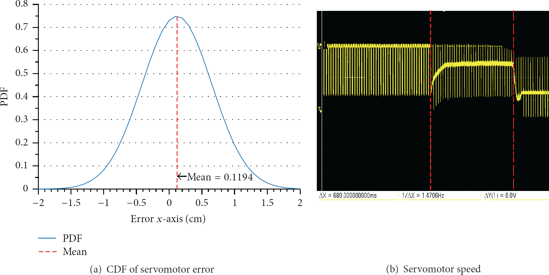
Servomotor characteristics.
6.1.3. Calibration Requirements
For recharging the leaf, we need to ensure that the laser beam correctly points at the solar panel of the leaf. The master might require recalibration once it returns to the same leaf after recharging all other assigned leaves. The frequency and the magnitude of this recalibration strongly depend upon the movement-error characteristics of a particular servomotor.
We measure this error for our servomotors by fixing the laser beam at a certain point, that is, the origin, before moving it a complete 180° along x-axis and then back. After each iteration we manually measure (with a metric rule) the tangential distance from the origin. We repeat this experiment 360 times. Figure 12(a) shows the PDF of these errors from the origin. We can clearly observe that the errors are bounded with a maximum error of 2 cm when leaf is 7 meters away, preventing cumulative error build-up with the mean value of 0.1194 cm. By performing simple trigonometric calculations on these values, we found the maximum angular error of 0.163°.
Technological Limitations. We emphasize that these error bounds are for a particular motor technology, that is, Futaba's s3003. Hence, these results should not be generalized to define the accuracy limits of laser-beaming used in an energy distribution architecture including LAMP. The selection of a motor technology is a trade-off between its cost and the required recalibration effort for a particular architecture. Since recalibrating the master is not within the scope of this prototypical study, our choice is biased towards the overall cost concerns of LAMP.
6.2. Charging Behavior of the LAMP Leaf
The choice of capacitor determines the charging and discharging dynamics of a LAMP leaf. A capacitor is like a water reservoir; the voltage across a capacitor is determined by the level of charge. For a fixed rate of charging, this charge level is reached later for a larger capacity of reservoir (its capacitance). Thus, while a smaller capacitance quickly reaches a defined usable voltage, it delivers lesser amount of current.
With this basic understanding we experimentally evaluate two important system parameters: the response interval
6.2.1. How Quickly Can a Leaf Be Energized?
We measure the response interval by focusing the laser beam on a completely discharged leaf and use an oscilloscope to observe voltage across a capacitor bank that we use to vary capacitance. The sudden changes in the voltage level on the oscilloscope clearly indicate the charging of the capacitor and the subsequent transmission of the first packet, allowing us to measure
Table 2 shows
Leaf

6.2.2. What Is the Minimum Interaction Interval?
We now want to understand the dynamics of the master-leaf interaction interval (
With the minimum
We find that
Table 3 shows

Discussion. Our evaluation of the energy dynamics of the leaf indicates that for the fastest interaction we should use the smallest possible capacitor size of 100 μF with the smallest
With these system characteristics defined, we next answer our two questions that will help define the practical limits of our LAMP implementation.
6.3. Application Duty Cycle and Data Rate
A first important question we want to answer is about the data rate during master-leaf interaction and the largest leaf duty cycle supported by LAMP. The duty cycle in this particular scenario is the duration for which the radio hardware of leaf remains active during
An answer to both these question helps understand the range of WSN applications that can be supported by our system. Using laser μ-power beaming mechanism, we expect to support a duty cycle of around 10% (cf. Figure 4).
We vary

LAMP application throughput: varying
6.4. LAMP Scalability
We finally evaluate the scalability of LAMP in terms of the maximum number of leaves that can be supported by a single master. The scalability of LAMP is strongly dependent upon
6.4.1. Survivability Limits for Leaves

In cluster mode, we can observe a similar pattern, as shown in Figure 14(b), but at a very different scale.
Overall, in both mesh and cluster modes, we see improvements in
6.4.2. Modeling Recharging Rate

If we want to maintain an always active network, the master must return to recharge each leaf before its power level falls below 2.1 V, which, by definition, happens after
6.4.3. Results
In an active network, the communication mode (Section 4.2) greatly impacts the duration of
Recall that, for mesh operation, all leaves use their radio for direct communication with each other even after the master relocates its laser beam. While any radio duty cycle can be supported, for simplicity we continue with the duty cycle determined by
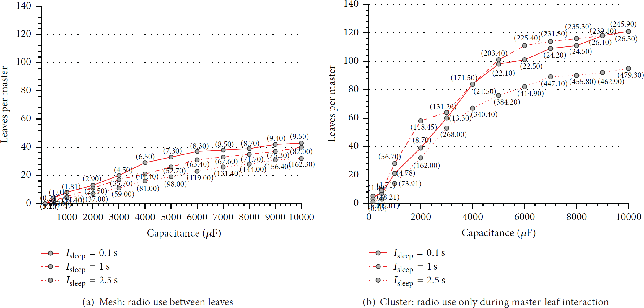
While maintaining an always-on network, LAMP scales up to 40 and 120 leaves per master in mesh and cluster modes, respectively (marker values represent recharging rate in seconds).
We next look at the cluster operation, where leaves only sense at an application defined rate with no intraleaf communication after the master relocates its laser beam (all data routing occurring through the master during a LAMP interaction). With lesser energy consumption we expect it to achieve greater scalability than mesh operation. Figure 15(b) validates this as LAMP can now scale up to 120 leaves per master with a recharging rate (or polling rate) of 26.5 s. This implies that, for a LAMP recharging rate of 26.5 s, again with a 10 mF capacitor, we can perpetually energize a 120-node WSN that networks only via masters.
One observation across both mesh and cluster modes is that LAMP scales better for smaller
Finally, if we want to support greater number of leaves we need to increase the LRR to greater than its
Overall, we can conclude that scalability of LAMP is well suited for practical WSN deployments and can be controlled by user-controlled parameters such as recharging rate, capacitor size, and sleep interval.
6.4.4. Effect of Improved Pan-Tilt on LAMP Scalability
The evaluation of LAMP in this paper is based on the hardware used in our prototype of LAMP master, mainly the pan-tilt mechanism. Since a different motor technology can change the localization accuracy of the pan-tilt mechanism, we, therefore, before concluding this section, evaluate the scalability of LAMP by disregarding the technological limitations of the motor technology used for masters. This evaluation is important to understand the scalability limits of LAMP when, for example, using the best pan-tilt hardware available in the market.
For this purpose we assume an ideal laser beam steering mechanism which provides
Hence, to evaluate the impact of such an ideal steering mechanism, we use

Improvement in scalability under mesh and cluster modes considering ideal pan-tilt mechanism. This evaluation is for
7. Limitations
Our work is the first attempt to decouple energy from sensing through a laser-based power beaming solution. As such, it lacks robustness and is not mature enough to be deployed in production or uncontrolled environments. To make our system more reliable and adoptive to real world scenarios, we identified following areas that require further research and proposed their possible solutions, as future work, below.
Line-of-Sight (LoS). LAMP architecture currently requires LoS between a master and a leaf. We believe that adding a third node-type, having mirrors, in our architecture can allow a power beam to route around obstacles. We see this achievable with previous work for outdoor settings on reflecting sunlight [8, 16] and indoors using mirrors on the ceiling as used for a non-LoS 60 Ghz wireless communication in data-center networks [40].
Localization, (Re)Calibration, and Robustness. While we do meticulously identify the calibration limits for our pan-tilt mechanism (Section 6.1), we agree that this issue needs further investigation for a fully functional deployment. We, as a future work, propose to replace the pan-tilt mechanism with a nonmechanical procedure, for example, electrooptic laser scanners [41], which use liquid crystals whose refractive index can be tuned by varying a voltage level. This method makes the steering system more robust, accurate, and easy to deploy.
We also believe that technology for precise aiming exists, with laser power beaming used on mobile UAVs 1 km away with cm-level accuracy [21]. Although the high cost precludes its use in our system, these costs will reduce as the technology matures. We thus believe efficient localization of leaves is a fertile area of future research.
Safety. A final area of concern is the safety issues when using lasers. We show that, by using just a 1 W laser, it is feasible to support low-power mote-class devices, although eye safety and long term exposure are still areas of concern. We can increase the safety by using “eye-safe” lasers at wavelength beyond 1500 nm [42]. Furthermore, we can use a very low-power (few mW) pilot beam while localizing the leaf and use the RF channel for feedback to move to full power transfer once aligned. This same channel can be explored to provide feedback such that when the power beam is broken (e.g., by animals or humans) the energy beam can immediately be switched off.
Despite these limitations, this paper is a significant step forward in identifying the limits and scales of a practical wireless energy transfer mechanism for WSNs.
8. Related Work
The scope of our paper is quite novel; to our knowledge, LAMP is the first system that uses laser μ-power beaming to build an energy distribution architecture for WSN. Unlike theoretical formulations [20, 43], this paper emphasizes the practical feasibility of a wireless energy transfer mechanism and thoroughly evaluates its limits to establish its feasibility boundaries. Moreover, unlike earlier work using light [8, 16], LAMP is not just an energy transfer mechanism; it is a complete architecture providing the abstraction of an energy plane that can transparently integrate with any existing sensing architecture to provide energy as a service.
We can broadly divid the related research into three main categories.
Physical Transfer. This paradigm of wireless energy transference in WSN is derived from store-carry-forward mechanism, which has been successfully applied to data collection in mobile ad hoc networks (MANETs) and WSN. In recent years, research community has used the same idea to transfer energy instead of data through the use of mobile chargers. These chargers visit each sensor node to recharge its battery. Li et al. [18] use the same idea and propose a mobile charger called Qi-Ferry (QiF) that must start from a depot (charging station), visit each sensor node for wireless recharging, and then go back to the depot. The authors define the Qi-Ferry problem which aims to maximize the number of sensor nodes charged during a single tour, while the energy spent by the mobile charger during the tour does not exceed its initial energy. They proposed a PSO-based heuristic to compute a tour that covers all the sensor nodes. Yao et al. [44] used the method of inductive charging by proposing two kinds of nodes in WSN, sensor node and charger node. In their proposed model, sensor nodes are static and are equipped with inductive coil to receive transmitted energy while charger nodes are mobile. In other approach [45] Powercast transmitter [23] is installed on the Acroname Garcia robot to move around and power the sensor node which is equipped with Powercast receiver in [45]. They proposed two heuristic based algorithms (greedy and greedy plus) to optimally charge the sensor nodes.
However, physical transfer of energy requires human-driven or robotic vehicular movement across the network, strongly limiting deployment scenarios. Furthermore, the energy requirement for a robot mobility also limits the practicality of such approaches.
Ambient Harvesting. A great deal of research deals with ambient harvesting of energy to buy longer lifetimes both in WSN [3, 46, 47] and in pervasive identification systems [27]. However, energy harvesting requires favorable conditions and thus restricts spatial deployment of nodes only at energy-rich areas. Similarly, energy harvesting alone is not sufficient to achieve our main goal, that is, to decouple energy and sensing planes in WSN. For this purpose our primary focus in this paper is to utilize abundant energy sources nearby a deployment to develop an efficient wireless energy transfer mechanism that can nonetheless support additional sources of ambient energy.
Light Reflection. Approaches such as elighthouse [8, 16] propose reflecting sunlight on to sensor nodes using mirrors. However, as we demonstrate in Section 3.2.3, the range and magnitude of such energy transfer are insufficient for running a mote-class device such as TelosB indefinitely even with LoS between the light source and the node. In [48], Wang et al. reflected 3 watt laser light on phosphor element to diffuse the laser light and charge multiple nodes at the same time but they were only able to harvest 0.132 mW at 1.5 meter distance.
9. Conclusions and Future Work
In this paper, we argue that present day energy transference technologies allow energy and sensing to be decoupled, thereby allowing energy management research to evolve independently from the sensing applications, much like power generation and consumption in a grid. Through a proof-of-concept prototype, we show that practical and cost-effective energy-sensing decoupling is now possible using off-the-shelf technologies. We compare different wireless energy transfer mechanisms to identify that laser μ-power beaming satisfies the fundamental goals of cheap, in situ, collaborative, and long lived sensing in WSN. We also present the first energy distribution architecture that enables decoupling energy and sensing planes. Our results demonstrate the feasibility of such an architecture in terms of data rate, duty cycle, and scalability. We believe that energy-sensing decoupling compliments all the existing research in WSN while opening an exciting new research dimension.
The argument for an energy plane abstraction opens up a great body of intriguing future work. Much like the early era of WSN, we envision research on both hardware and software aspects of small scale energy distribution architecture. On the software side, we expect refinement in the basic API that sensing applications (in the S-plane) will use to request energy (in the E-plane) through an energy transfer technology. Similarly, building the entire network stack for the E-plane elements, including an optimized version of our current LAMP protocol, is a promising future direction. On the hardware side, we see mobile and pervasive computing demands push the envelope of wireless energy technology. We see this being used to build more compact and low-cost technologies, with sensors being able to measure their energy “RSSI.” Furthermore, employing different technology for energy distribution will require a different implementation of the energy plane abstraction. We even see potential in modulating the energy transfer to enable communication between devices, thus precluding the need of using the expensive radio for master-leaf interaction.
Footnotes
Conflict of Interests
The authors declare that there is no conflict of interests regarding the publication of this paper.