
Abstract
Radio-frequency identification (RFID) techniques are widely used in many ubiquitous applications. The most important usage of RFID techniques is to read the tags within a reader's interrogation area such that the objects attached with those tags can be identified. In real practice, it is common that a tag is physically in the interrogation range but cannot be read by the reader, due to the multipath effect and other interference. This phenomenon, namely, the hidden tag problem, is a big challenge to achieve high identification rate. To address this problem, most prior works depend on empirical or measurement-based methods to tune the transmission power for readers. Such a case-by-case solution is impractical for generic implementation. In this paper, we theoretically and experimentally explore the reasons why hidden tag problem occurs. To alleviate its impact, we propose a unified and measurable model to formulate this problem and its impact. Different from previous works, our solution is generic and fully compatible with existing EPC C1G2 protocol. The analysis and measurement based on our model can help to design and deploy RFID systems with high identification rate.
1. Introduction
Radio-frequency identification (RFID) technology experiences a proliferation in the past decade [1, 2]. It has been widely used for identifying objects attached with tiny, low-cost, and wirelessly accessed tags. To identify those objects, the RFID reader usually continuously scans the tag within its interrogation region. However, it is very common that a tag physically staying in the interrogation region cannot be read by the reader, due to the multipath effect or interference. This phenomenon, namely, the hidden tag problem, incurs a severe performance degradation to current RFID systems. A report from Impinj, a famous RFID manufacture, shows five factors for successfully reading tags [3], such as the performance, flexibility, and reliability. Those factors, however, are seriously affected by the hidden tags. According to recent statistics, hidden tag problem causes 70% of loss in the real RFID applications [4].
We believe that it is important to understand the performance of existing UHF RFID systems under various settings in combination at a detailed realistic experiments. We are interested in the question concerning which reasons that trigger hidden tag problem occur and further explore the theoretical explanation combined with realistic experiments.
Many approaches [5–8] have been proposed to tackle this problem. Most of them are empirical [5, 6] or measurement-based [7, 8]. To our knowledge, reasonable and generic theoretical analysis on the hidden tag problem from the electromagnetism perspective is still missing. Meanwhile, prior works also pay little attention to the intrinsic nature of antenna design, which may degrade the identification performance. Therefore, the hidden tag problem remains challenging and severely degrades the performance of the RFID system.
We believe that addressing this problem needs a combination of comprehensive theoretical analysis and validation in real deployments. In this paper, we first explore the essence of the hidden tag problem by studying the interaction patterns of RFID communications. In particular, we analyze the antenna gain and impedance of RFID devices to explore how their impacts cause the occurrence of hidden tags. We also employ a Rayleigh channel fading model and spatial selective multipath signal to theoretically formulate the signal energy at different positions, yielding a unified model for explicitly explaining the reason why hidden tag problem occurs. Through extensive experiments, we validate the proposed unified theoretical model. Furthermore, we highlight the root causes of hidden tags based on our experimental results, providing a guidance to address the problem to future RFID system designs.
The contribution of this paper can be summarized as follows. We define the hidden tag problem in RFID systems and explore it from the perspectives of electromagnetic and digital communication. To our knowledge, we are the first to analyze this problem from such an integrated way. We propose a unified and measurable model to characterize the signal features in real applications. More importantly, the root causes of hidden tag problem can be revealed based on the proposed model. We present our implications and lessons learned from the empirical studies. Our experiences can facilitate mitigation of the negative influence of the hidden tags in practice. We also provide useful guidance for future RFID designs and deployments.
The rest of the paper is organized as follows. Section 2 briefly reviews the literature of RFID tag identification, missing tag detection, and measurement and analysis of realistic system. Section 3 introduces the theoretical models and realistic experimental settings of our study. Section 5 presents the detailed root causes of hidden tag problem occurring in terms of three categories. Section 6 illustrates the limitations of our work, and Section 7 gives our implications and lessons learned from the empirical study of hidden tag problem. We conclude our work and give future works in Section 8.
2. Related Work
RFID is a promising technique to enable remote and automatic identification for a variety of applications. Intuitively, both the dedicated design and the RF signal interferences are potential factors to cause hidden tags [9].
In RFID systems a tag usually replies to the readers query in a randomly chosen slot. When two or more tags reply to the reader in one slot, a collision happens. Collisions, however, are a main cause of hidden tags, because the reader cannot decode their IDs from collided signals. There are two categories of anticollision protocols: slotted-ALOHA-based protocols [5, 10] and tree-based protocols [11, 12]. Both of them can address the hidden tag problem caused by collisions. The work in [13] designed two protocols, a trusted reader protocol (TRP) and an untrusted reader protocol (UTRP), to find out whether a set of tags are intact or not. The two protocols do not require the reader to collect IDs from tags, providing users privacy protection as well as high efficiency. Different from TRP, EMD [14] allows a tag to probabilistically decide whether it answers the reader query even after it chooses a slot for replying. Different from the approaches [13, 14] that only concentrate on the time efficiency, MSMD [15] adopts multiple hash seeds to reduce the number of collisions, resulting in the reduction in both energy consumption and execution time.
In large-scale RFID systems, multiple readers are synchronized as one logical reader for further improving the time efficiency in identification [16]. However, a reader-to-reader collision may occur [8]. Instead of collecting the response from each tag, some other works, like P-MTI [17], deal with the aggregated responses from physical layer symbols. P-MIT makes use of the compressive sensing technique to reconstruct tags’ responses.
Passive RFID systems depend on the backscattering communication to achieve interaction between readers and tags. However, backscattered RF signals are vulnerable to the multipath effect and ambient interference, especially in indoor environments. Recently, many works focus on the factors influencing the identification performance. Aroor and Deavours [18] present a series of experiments to measure the technical capability of passive UHF RFID tags and readers. It shows that the identification performance would degrade significantly if the tag is near metal or water surface.
The work in [19] is the first detailed, low-level measurement study on the EPC C1G2 UHF reader under the setting from real deployments. The results show that physical layer effects, such as the errors and multipath effects, are important factors to degrade the overall performance. Xie et al. [20] expand the experiment to a relatively large number of tags. The authors build a model to depict how various parameters affect the reading performance of mobile readers. The factors include the readers’ power, moving speed, and tag density. A recent work, Blink [21], measures the link quality, mobility prediction, and rate adaptation for improving the link layer performance. Unlike prior works, our approach aims to find the gaps between the theoretical results and realistic experiments when addressing the hidden tag problem for ultimately improving the identification efficiency.
3. Impact Factors of Hidden Tag Problem
In this section, we firstly introduce the reasons that may cause hidden tag problem and then investigate the factors that should be considered for constructing our generic model.
3.1. Reasons of Incurring Hidden Tags
We categorize the reasons into three main aspects. First, the tag-to-tag interference may lead to hidden tag problem. From the perspective view of electromagnetic engineering, the antenna gain and impedance among nearby sensors are the major factors that can influence the identification performance. We experimentally and theoretically compare the critical distance to figure out the noncoupling distance of pairwise tags. Second, the tag-to-reader interference is also considered as a main source of generating hidden tags. We mainly discuss the channel diversity and transmission power changes to illustrate the impact from tag-to-reader interference. Third, the environmental interference is another major aspect that degrades the whole performance by incurring the hidden tag problem. We employ Friis transmission equation and spatially selective multipath effect to formally model the signal fading and multipath influence. In order to validate the theoretical model, we conduct extensive experiments under three typical environmental settings, named open-space environment, semi-open-space environment, and enclosure space environment, respectively.
3.2. Link Quality
Link quality is one of the most significant factors that influence the hidden tag that occurs. For an RFID system, there are two separate wireless links shown in Figure 1. One is the reader-to-tag communication (the forward link) and another is the tag-to-reader communication (the backward link). These links are dominated by the reader transmission power and path loss.
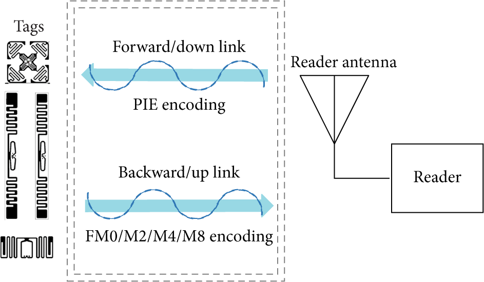
A typical RFID system has two logical wireless links, the forward link and the backward link.
3.2.1. Reader Transmission Power
Tuning the reader transmission power is an effective way to reduce the number of hidden tags. However, we cannot increase the transmission power too much. The reader transmission power is determined by a combination of practicality and regulation. For example, in China, the government allows RFID operations within the band 920–925 MHz. However, the equipment itself must obey certain operating regulations to avoid the unlicensed use. For example, the off-the-shelf RFID reader Impinj Speedway R220 cannot set transmission power larger than 1.8 W.
In our experimental validation, we will dynamically change the transmission power from the maximum value to the minimum value, recording the critical power and RSS of a tag. Here, the critical power is the minimum transmit power for the reader that can just detect the particular tag. Indeed, it is helpful to study the critical distance, power, and RSS of tags, because setting the reader with those values will easily trigger the occurrence of hidden tags and further lead us to detect hidden tag that occurs.
3.2.2. Path Loss
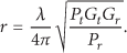
Path loss is another potential factor incurring hidden tags. The path loss is defined as the difference between the power delivered to the transmitting antenna and obtained from the receiving antenna. Generally speaking, finding the path loss requires knowing some details of the antenna operation. We assume that the transmitting antenna radiates in all directions with the same power density, which means the transmitter is isotropic. We can picture the radiated power as being uniformly distributed over a spherical surface at any given distance r from the reader antenna. We set the transmission power as

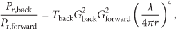
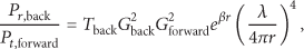
Since the backscatter communication comprises the forward link and backward link, the received signal of forward link can be calculated using the Friis transmission equation. The backward link shows how the power is backscattered to the reader. The backward link path loss can be derived from the Friis transmission equation, and the power of reader received is formulated as follows:
To provide the empirical results of above behavior, we estimated the path loss under independent experimental settings in an enclosure space, a semiopen space, and an open space environment.
Implications: The gap between the theoretical model and the experimental results seems a bit large. And they show different patterns under various experimental settings.
3.3. Antenna Gain and Impedance
The hidden tag problem is highly related to the gain of the tag and reader antennas. RFID systems, especially those passive UHF ones, usually use directional antennas in their readers. The directive gain along the direction in which tags are most likely to be found is known as the directivity of the antenna. The directivity multiplied by the radiation efficiency is the power gain of the antenna (G). The gain is also influenced by the power in the sidelobes and deviations of a couple of dB from this simple formula are not uncommon.
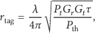
It is known that the physical identification range is the minimum value of the tag-to-reader activation distance and the reader-to-tag backscattering distance. From (1) (Friis transmission equation), we can quickly get another transformation of Friis transmission equation:

Furthermore, we plot Impinj E41B and E41C tags as shown in Figure 2, using HFSS (High Frequency Structural Simulator) [23]. HFSS is used to simulate the antenna electromagnetic field radiation of those tags. Clearly, Figure 2 describes different electric diagrams of two tags; the different impedance may lead to such diversity, and we demonstrate different results in the following discussions.

Impinj E41B and E41C tag.
3.4. Multipath Propagation
Multipath propagation leads a nontrivial impact on the successful reading rate of tags. It is an inherent wireless channel characteristic and has been widely studied in previous works [1, 2]. However, the physical environment diffracts or scatters the radio waves such that the signal cannot be easily captured and well formulated. Furthermore, the signal may be calculated accurately in an enclosure space under rich multipath effects. Hence, we explore the received signal strength of the reader and compare with the realistic experiments.
Let us consider a multipath propagation environment of an RFID application. The radio waves will be overlapped in the space so the composite signal observed on a receiver antenna will be the superposition of the effects of each multipath signal. Figure 3 illustrates the signal received by the antenna under this situation. The theoretical model of the multipath propagation is stated as follows [24]:

The angle of arrival of received multipath radio waves.
The wireless channel selectivity can be classified into three types: frequency selectivity, spatial selectivity, and time selectivity. Since the deployment of tags is static and fixed, the frequency selectivity and time selectivity can be ignored. We only consider spatial selectivity in the following analysis.
For simplicity, we assume that signal bandwidth is small enough such that the channel is well modeled as frequency flat. We define a reference position, A, at which the received signal has the form
We aim to calculate the signal received at a certain position compared with the experimental results to study the impact of multipath.
4. Unified Model and Experimental Settings
4.1. Unified Friis Transmission Equation
From the above analysis, we refine the basic Friis transmission equation by adopting the factors that may influence the signal received by the RFID reader, which are missed in prior works. For instance, the effect of impedance mismatch and absorption can be included by adding additional factors. We rewrite (2) as follows:

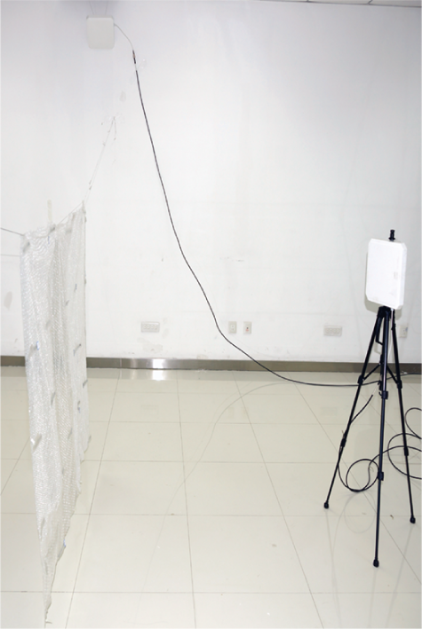
4.2. Experimental Settings
In our experiments, we employ an off-the-shelf UHF RFID reader (Impinj speedway R220), two circularly polarized antennas (Larid S9028PCL), and 25 Impinj E41B and E41C passive tag. The E41B and E41C tags are typical UHF tags in the market. The reader communicates with tags and collects their IDs. We record and evaluate the critical power, RSS, and reading rate of each tag under three environmental settings, that is, the enclosure space, semiopen space, and open space environments. The results are depicted in Figures 4, 5, and 6, respectively.
Enclosure space experiment.
Semiopen space experiment.
Open space experiment.
Scenario 1 (enclosure space).
The enclosure space is a
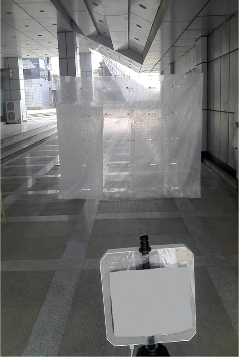
Scenario 2 (semi-open-space).
We choose a corridor which is only open in the direction of both ends. In this experiment, tags are deployed close to a wall at the right side (1 m away), but far away from the wall at left side (more than 4 m). Other settings are similar to Scenario 1.
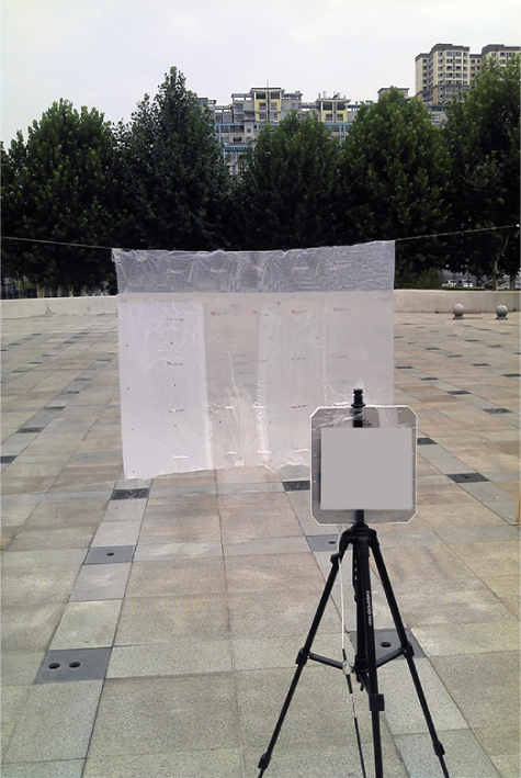
Scenario 3 (open-space).
The experiment is conducted in an open-air square in our campus. Other settings are similar to Scenario 1.
5. A Closer Look at Hidden Tags
To investigate the root causes of hidden tag problem, we perform correlation analysis between the causes and factors potentially triggering the occurrence of hidden tag.
Intuitively, the root causes that incur hidden tag problem can be summarized into three aspects, tag-to-tag interference, tag-to-reader interference, and system-to-environment interference, respectively. In this section, we discuss the detailed root causes and the corresponding factors of them.
5.1. Tag-to-Tag Interference
We employ HFSS (High Frequency Structural Simulator) [23] V10 to simulate the antenna electromagnetic field radiation of Impinj E41B and E41C tags. We take the parameters listed in Table 1 to establish our model. To calculate the radiation, we employ a cuboid boundary condition (
Parameters used in the simulation to model the radiation of Impinj E41C tag.

5.1.1. Inductive Coupling
Inductive coupling is one important reason that leads to the occurrence of hidden tags. When two tags are physically close to each other, the antenna inductive coupling will decrease the electric diagram.
Figures 7 and 8 depict the single tag electric diagram of Impinj E41B and E41C tags. The original intensity of E41C tag is smaller than E41B tag, indicating that the E41C is quite suitable for being attached to high-dielectric-constant surfaces. The electric diagram of pairwise tags under different distances cannot be directly observed from the HFSS simulation. However, we can infer that the distinct distances exhibit quite different characteristics. When one tag is 30 cm away from another one, the electric diagram shows little difference as the inductive coupling is negligible.

Tag electric diagram of Impinj E41B.

Tag electric diagram of Impinj E41C.
5.1.2. Antenna Gain
Antenna gain refers to the fact that, for a receiving antenna to be located along the direction of maximum power density, the received power is increased relative to that of an isotropic antenna just as if the output power of the directive antenna had been increased by a factor of G. The higher the gain of a directional antenna, the more narrowly the energy radiated focuses.
If the antenna radiates most of the energy it receives, the gain and directivity are almost the same. In this case, the size of the beam is inversely proportional to the gain. The beam angle is roughly the square root of the beam solid angle when the beam is reasonably symmetric. The antenna gain can be derived from the power. This power is called the effective isotropic radiated power. We can modify the Friis equation by some main contributions described as follows.
From (3) we know that, keeping other variables unchanged, varying the tag antenna gain may lead to different activation distance. We conduct several experiments to compare the theoretical results with the values. The theoretical parameters include the following:
Theoretically, the activation distance increases with tag antenna gain increasing. However, from Figure 9, we find a huge gap between theoretical value and practical value. This may be caused by the ideal parameter settings or the ideal environmental assumptions. It shows that there is a difference of activation distance between E41B tag 3022 and E41C tag 2004. Limited by experimental environment restriction, the tuning range of reader transmission power is narrow. Under low reader transmission powers, the signal itself appears unstable, so the activation distance lines of two tags are mixed together. However, when increasing the transmission power, the results tend to be stable and start conforming to the theoretical results.

Impact of antenna gain for the activation distance.
5.1.3. Tag Impedance
For general purpose, UHF RFID tags should be usable for both pallet level and item level. For instance, the E41B tags are designed to provide long reading ranges on low-dielectric-constant materials. These logistics RFID tags enable a cost-efficient solution for apparel tagging applications.
The E41C are UHF tags which are also general purpose RFID tags for logistics but, unlike the E41 and the E41B, are more suitable for high-dielectric-constant surfaces. Typical applications include tagging of carton and plastic boxes, apparel, books, and file folders.
5.2. Tag-to-Reader Interference
5.2.1. Channel Frequency
An RFID reader transmits on a frequency within 50 channels in the band of 902–928 MHz. In USA, Federal Communications Commission (FCC) allows maximum 0.4 s usage of each channel within 10 s, which means 25 channels can be used rather than 50. In China, the operation band is 920–925 MHz, and the Impinj reader offers us 16 channels frequencies starting from 920.625 to 924.375 MHz. The reader hops among the 16 channels automatically or mutually. To figure out whether and how the channel frequency affects the performance of identification, we demonstrate several results from our realistic experiments in the enclosed-space. Firstly, we recorded every reading data of our target tags under the hopping mode within a duration of 32 s, ensuring every channel is utilized at least once. Then, we incrementally changed the channel frequency, from channels 1 to 16, and recorded the data collected at each channel within 5 s. The distance of the reader antenna to the tag is 0.6 m, and the transmission power is 10, 20, 30 dBm for comparison.
Figure 10 shows the tag's reading rate in each of the 16 channels under two modes. We find that when at the critical condition, different channels show different ability. Under the frequency hopping mode at the channels 5, 6, 7, 8, 9, 10, and 16, tags present smaller values of reading rate at other channels. Also, their reading rates are even less than half of the optimal value, which is about 33 times per second deriving from large amounts of experiments. When fixing to channel 11, the reading rate is nearly zero. This may emerge as a hidden tag in practice. While in Figures 11 and 12, when the transmission power is enlarged, all channels show a similar reading rate, either in the hopping or fixing mode. Moreover, we compared the reading rate in different channel frequencies between different readers. Figure 13 shows that, for a given reader, the reading rate is almost the same when the power is 30 dBm. UESTC reader's reading rate is lower than that of Speedway. Figure 20 is derived from further experiments. We randomly select 20 locations in the room, and in each location we repeat the reading experiment 5 times with 60 s individually. The results are the average value in each channel frequency. We find that the overall trend of reading rate is almost similar for two kinds of tags.

Frequency hopping versus fixed frequency (power equals 10 dBm).

Frequency hopping versus fixed frequency (power equals 20 dBm).

Frequency hopping versus fixed frequency (power equals 30 dBm).
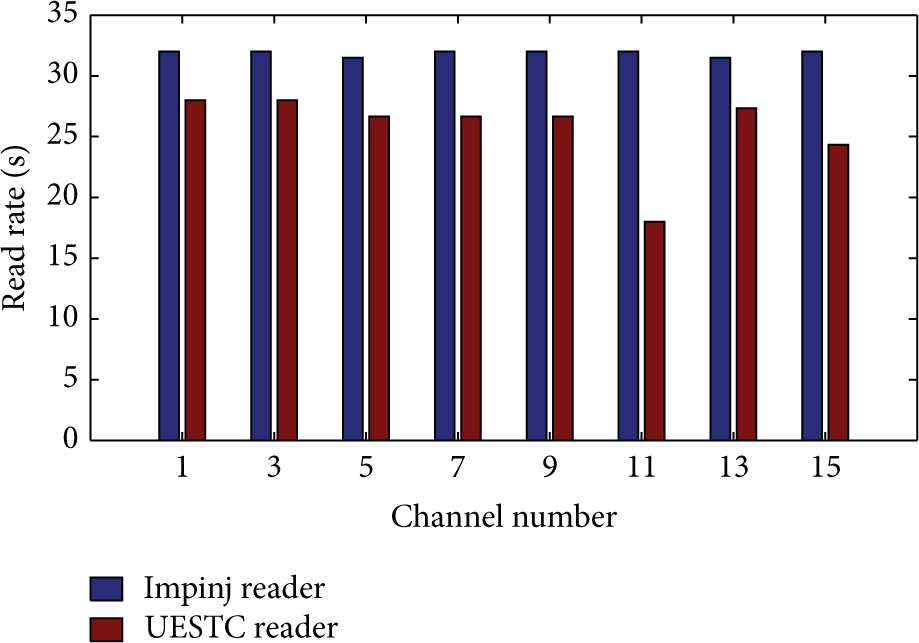
Impinj reader versus UESTC reader (power equals 30 dBm).
In general, the performance of various channels depends on the deployment, external interference, or reader hardware. To enhance the effectiveness of identification, we suggest artificially choosing the top specific number of channels and using fast hopping mode.
5.2.2. Power
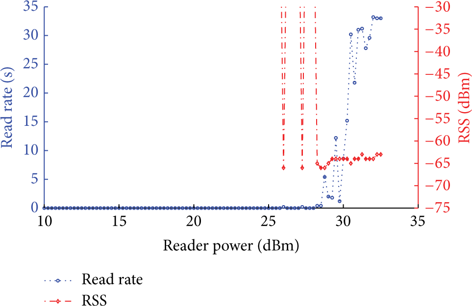
Intuitively, the reader's transmission power is a vital factor for RFID systems. On the tag side, RSS can be used to reflect the transmission power. According to our observations, the RSS varies when changing the transmission power settings of the reader. In most cases, increasing the transmission power for a reader leads a higher RSS to the tag. However, it is not always true. Figures 16 and 18 demonstrate this phenomenon. Moreover, the reading rate of a tag becomes unpredictable and uncontrollable at the critical power. In Figure 14, when the transmission power is 32.5 dBm, the reading rate of a tag is less than that with the transmission power setting of 13–30 dBm. It indicates that increasing the transmission power for a reader may not be always effective to improve the reading efficiency, not to mention a large overhead incurred by such an increase (see Figures 15, 17, and 19).

The reading rate versus RSS with distance = 60 cm.

The reading rate versus RSS with distance = 100 cm.

The reading rate versus RSS with distance = 200 cm.

The reading rate versus RSS with distance = 300 cm.
The reading rate versus RSS with distance = 400 cm.

The reading rate versus RSS with distance = 500 cm.

Impinj tag versus Alien tag (UESTC reader; power equals 30 dBm).
5.3. System-to-Environment Interference
5.3.1. Channel Fading
Fading is a fundamental problem in all radio based systems. In real deployments, there are often several objects between the reader and tag, resulting in the phase delay or variation on the received signal. Fading can also produce path loss and hence decrease the energy received by the reader antenna. When the energy is lower than certain threshold, the tag will not be successfully identified. Therefore, we discuss the path loss from both the theoretical and practical aspects. In Figure 21, we plot our observation on the number of identified tags over 16 channels under 90 power values. In each channel, the reader stays 5 s. We can see that the number of identified tags significantly differs with the minimum power value. Between the transmission power of 13 dBm to 30 dBm, at each channel the tag behaves analogously and has a stable reading count. Figure 22 depicts the relationship between the transmission power and the number of identified tags on channel 3 under various distances. When the transmission power value becomes 30 dBm, the reading efficiency is relatively stable. With above observations, we then conduct the channel fading experiments under 3 scenarios described in Section 3.4 at a constant channel frequency (921.125 MHz) and transmission power (30 dBm) and then change the distance from 0.6 to 5 meters between the reader's antenna and tag.

Channel changes from 1 to 16, the identification efficiency comparison.

Channel 14 at a fixed frequency and power, we change distances which vary from 0.6 to 5 m.
The value required for this experiment is calculated by (2), where
Figure 24 shows the experiment results. Theoretically, the value of path loss increases when the distance between the tag and reader is enlarged. However, it is not exactly the truth. For example, the path loss increasing at 5 m is larger than that at 4 m in the enclosed-space scenario. This phenomenon can be explained by the multipath effect. In this experiment, the tag at 5 m away from the reader is just against the wall. Radio signals are reflected to the reader, strengthening the received RSS at the tag.
5.3.2. Multipath Effect
The signal radiated by the reader antenna may travel along different paths to a tag simultaneously. The signals along multipath overlap at the receiver antenna, leading to a large variance of the received signal. Indeed, multipath effect is a double-edged sword for RFID systems. Sometimes it makes a line-of-sight object unreadable, but sometimes it may enhance the reading efficiency of some tags with special angles or positions.
Figure 23 shows the different tag's reading performance in

The congruent relationship between power and RSS of

The path loss comparison between different scenarios and experimental results with various distances of tags.
First, under all deployments, an obvious trend is that if tags are unidentifiable at lowest power, when increasing the transmission power of the reader, they become identifiable. This implies that sufficient power is necessary for guaranteeing high successful reading rate of identification. Second, in the enclosure space scenario and the 2 m cases, it is true that as the power increases, the RSS value also increases. Even when there exist abnormalities, the difference of RSS is marginal. Third, in the 4 m case for both the semi-open-space and open-space scenarios, outliers appear frequently. There is no exact proportional relationship between the transmission power of readers and the RSS of tags, as the results obtained in the enclosure space from tags 4, 13, 18, 19, and 20, in the semiopen space data from tag 9, and in the open-space from tag 13. These tags became hidden tags when the transmission power is at a specific value but visible after the transmission power is enlarged. On the other hand, when the transmission power increases, the multipath effect is strengthened. Some paths may cause interference cancellation such that the RSS of some tags is below the reader's lowest sensitivity, and hence they became hidden suddenly. To avoid this and improve the reading rate, we can gradually change the power.
In summary, the multipath effect may cause RSS changes, and then in some cases the RSS signal may be strengthened, while in other cases, the multipath effect makes tags hidden.
6. Limitations
Our study presents a unified model based on the analysis between theoretical results and empirical results. Our model explores core reasons responsible for the hidden tag phenomenon. The data we collected for analysis is based on the reader independent operations. The settings of experiments may not be exactly the same, since some unpredictable factors interfere with the system significantly. For example, in the open-space scenario, the influences of wind cause a sudden and irregular jittering on the foaming-attached tags. Since we cannot model the interference involving the weather impact, we conducted our open space and semiopen space experiments in a clear day, in order to alleviate the uncontrollable environmental impacts.
Another fact is that the theoretical analysis of our model is based on previous works. But we modify the Friis transmission equation to meet the RFID systems. In case of using any requirements that violate ours, the empirical results can be different. However, for the normal static RFID applications, we have already done relative fundamental results.
7. Lessons Learned
In this section, we summarize our observations, implications, and lessons learned from this study.
Observation 1. Tags from different manufactures experience different identification rates under the same settings. Similarly, the UESTC reader performs quite different from the Impinj reader as experimental setting changes. Implication 1. RFID devices perform distinctly in terms of performance. Although the commercial devices are more reliable than the products of labs, however, the main reason that causes the hidden tag problem is not coming from the difference of the devices.
Observation 2. In Section 5.2, when the power equals 10 dBm and channel frequency is fixed, identification rate performs better than the hop mode. However, if the channel is set to 11 or 12, the fixed frequency mode experiences no tag reply. Implication 2. The performance of various channels depends on the deployment and external interference. To enhance the effectiveness of identification and alleviate hidden tag problem, we suggest artificially choosing specific number of channels and using fast hopping mode.
Observation 3. Through our analysis in Sections 4 and 5, we know that the hidden tags are not always hidden, especially in the enclosure space environments. To alleviate hidden tag problem we give a general model to characterize the signal strength. Implication 3. The formulated model considers three aspects of the interference, tag-to-tag interference, tag-to-reader interference, and system-to-environment interference. However, there are still some aspects we could focus on, such as characterizing the environmental changes and different material features.
8. Conclusion
In this paper, we aim to explore the hidden tag problem that occurs in the RFID applications. To deal with this problem, we present a unified model to measure the reader's received signals, so as to alleviate the hidden tag problem. We also explore the main factors that cause hidden tags and modify state-of-the-art Friis transmission equation. Based on extensive experiments, we validate the effectiveness of our proposed unified model. The future works will focus on exploring multidimensional factors that influence the hidden tags in real applications.
Footnotes
Conflict of Interests
There is no conflict of interests regarding the publication of this paper.
Acknowledgments
The authors thank Professor Jinsong Han for his valuable suggestions on improving the quality of this paper. This work is partially supported by the National Natural Science Foundation of China (NSFC) under Grants nos. 61325013, 61373175, 61190110, 61402359, 61472312, and 61272456 and the open fund ITD-U14004/KX142600011. This work is also partially supported by the Overall Innovation Project of Shaanxi Province Science and Technology Plan (2012KTZD02-03-03) and the Fundamental Research Funds for the Central Universities under Projects nos. K5051323005 and BDY041409.