
Abstract
In order to improve the location accuracy in the complicated greenhouse environment, a positioning system is designed in this paper. According to RSSI data in the greenhouse, the parameters of the path-loss model are modified. Besides, least square estimation is used to filter RSSI data to eliminate random disturbance. Based on RSSI, the blind node is positioned by triangle centroid location method. Finally, to lessen the negative influence of steel pillars in the greenhouse, a region segmentation mechanism is introduced to the system. Experiments prove that our positioning system has higher accuracy in the greenhouse.
1. Introduction
Modern facility agriculture control system is developing from the control over the microclimate to the control based on crops' physiology and ecology in the greenhouse [1, 2]. It plays an important role in the control system that accurately monitoring of each part of crops. However, the greenhouse environment data of crops' different parts and light intensity of greenhouse's different regions have fluctuations in a day. If Wireless Sensor Network (WSN) with the fixed nodes is selected to transmit data, it will cause the problem of data redundancy, node resources wasting, and excessive energy. Thus, the mobile WSN nodes are necessary for their great flexibilities [3–5].
Once the mobile WSN nodes are used, the positional information of mobile nodes is essential for the monitoring system. But there are lots of factors influencing the location accuracy, such as WSN radio signal being blocked by the steel structure of greenhouse or by multipath effect in indoor environment [5, 6].
In this paper, a positioning system based on Zigbee WSN which is suitable for greenhouse is developed to solve these problems. The region segmentation mechanism is also proposed to solve the problem of WSN radio signals being blocked by the steel structure of greenhouse. Experiments prove that the positioning system has higher accuracy in the greenhouse.
2. The System Structure Design
Generally, WSN localization algorithms include Range-Based Localization Schemes (RBLS) and Range-Free Localization Schemes (RFLS) [1–3]. Comparing with the RFLS, RBLS has a higher accuracy. But it requires distance or angle information between nodes. Time of Arrival (ToA), Time Difference of Arrival (TDoA), Angle of Arrival (AoA), and Received Signal Strength Indication (RSSI) are the most common approaches to obtain distance [4]. In Range-Based WSN, the accuracy of localization system depends on precise estimation of nodes distance [5–8]. Considering the cost of greenhouse construction, the low-cost RSSI method is preferred.
In this paper, the entire greenhouse is preliminarily split to 6 regions by WSN node arrangement. Then, according to RSSI, these greenhouse regions are segmented further to optimize the position system.
2.1. System Architecture
The whole localization system can be divided into two layers: WSN layer and PC client. The system architecture is shown in Figure 1.
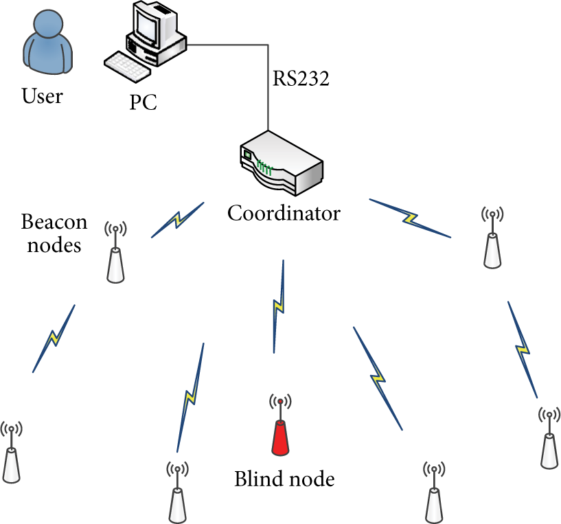
System architecture diagram.
The WSN layer consists of the stationary beacon nodes and the mobile blind node. The network structure is a tree structure. Coordinator is the core of WSN, and its main work is building and maintaining the network. Beacon nodes collect data and upload to coordinator. Then coordinator preprocesses data and uploads RSSI data to PC by RS232.
The major jobs of PC are processing the data which is uploaded from WSN, assorting nodes and filtering RSSI. The optimized data obtained from the calculation of PC is used to calculate the location of the blind node. In our system, WSN and PC are connected with serial port.
2.2. Node Arrangement Scheme
In this paper, the size of the greenhouse is

Node arrangement schematic diagram.
3. Hardware Design
In this paper, Zigbee WSN is selected as R&D platforms. The CC2530 chips are the cores of the coordinator, the beacon nodes, and the blind node.
3.1. Nodes Design
CC2530, launched by TI corporation, is a solution of system on chip (SOC). The chip supports IEEE802.15.4 and Zigbee PRO. And it integrates 2.4 GHz direct sequence spread RF transceiver and high-performance 8051 CPU. CC2530 has the characteristic of low power consumption, high sensitivity, and strong anti-interference capacity.
CC2591 is a 2.4 GHz RF front end with high integration and lower power consumption. The integrated power amplifier has ability to amplify output power to 22 dBm. The communication distance could be extended over 10 times. Based on CC2530, RF front end CC2591 enhances reliability of the data transmission.
3.2. Solar Power Supply System Design
Dry cells are selected to be a conventional power system. But dry cells are unable to supply stable voltage. To eliminate the negative effect, different nodes choose different power systems. Because coordinator has no special requirement, it selects direct feeding system. Blind nodes and beacon nodes select solar power supply system. Solar power system not only saves energy but also has ability to supply stable 5 V voltage to eliminate random error which is caused by power supply.
Solar power supply system consists of 3 modules, energy conversion, energy storage, and energy control. Figure 3 shows structure of the solar power supply system.
Energy conversion: single silicon solar cell panel constitutes the energy conversion module. It is used to supply energy to node and battery under bright light conditions. Energy storage: energy storage module consists of capacitance and silicone battery. Extra solar energy is stored in the battery under bright light conditions and supplies power under dark conditions. Energy control: to manage charge and discharge of battery, energy control module chooses work patterns according to the voltage of solar cell panel.

Solar power system structure diagram.
4. Software Design
Software design includes Zigbee node program design and PC program design. Node program is responsible for transmitting data. And PC program takes charge of data processing.
4.1. Node Program Design
Using a task scheduling mechanism like Operating System, Zigbee Protocol stack achieves the basic functions, such as building and maintaining network and joining network. Beacon nodes can receive the location request from the blind node and upload RSSI to PC. The process of node software is designed as shown in Figure 4.

Node program flow diagram.
There are 3 steps in WSN node software program.
Location request: the blind node broadcasts location request with identifier. Respond request: all of the beacon nodes receive location request with identifier. Then they analyze RSSI from the request and upload to coordinator. Check beacon response: coordinator collects RSSI of every beacon node. If any Beacon's RSSI is lost, coordinator will broadcast location request again.
4.2. PC Program Design
The main works of PC program are filtering and optimizing RSSI from coordinator. With the distance which is converted from RSSI, the specific location of the blind node is calculated in the system.
4.2.1. RSSI Ranging Model
When radio signal transmits over short distances, RSSI is disturbed by reflection, refraction, or diffraction of environment. Due to the steel structure in the greenhouse, moving people, and other greenhouse facilities or crops, signals often have many paths to arrive to receiver. And this phenomenon may result in multipath fading effect. It means that the received signal is superposed by many signals of different paths. In indoor environment, None Line of Sight (NLoS) is effected by Rayleigh fading, while Line of Sight (LoS) is effected by Rician fading [9]. And the two fast fading have a significant impact on communication system. Therefore, to indoor radio signal transmission model, multipath fading effect is the major factor of error.
The path-loss model which is suitable for free space is inappropriate. In this paper, log normal distribution model is used to estimate radio signal loss. The following mathematical expression is

Equation (2) is the simplification of (1). Because RSSI value is negative, (2) selects absolute value for convenient calculation. Equation (2) is

Equation (2) is the relational expression of distance and RSSI. With (2), the parameters of path loss model in greenhouse could be estimated.
4.2.2. Least Squares Filter
Due to multipath effect and other random noise in the greenhouse, RSSI which location nodes receive has great error, and the accuracy of location is reduced. In this case, it is necessary to carry on filter processing to RSSI. Least squares Filter is selected in this paper. Least squares method is a classical parameter estimation method. It estimates parameters of regression model from an error fitting perspective [10]. Experiment proves highly effective.
According to RSSI of one beacon node, the equations are as follows:

To simplify the equations get (4) as follows:

In (4),

To solve (4) with least squares method, the result is
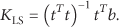
Then the estimation of distance is

4.2.3. Triangle Centroid Location
The three-bonier measurement and the triangulation method are common methods of RBLS. Because of the influence of multipath effect and random error, it is often the case that 3 location circles do not meet in one point. In this paper, triangle centroid location algorithm is selected to locate the blind node. The 3 location circles intersect with one another. With 3 intersections, a triangle could be found. And the centroid of the triangle is the position of the blind node. The principle of triangle centroid location is shown as Figure 5.

Triangle centroid location.
Triangle centroid location uses RSSI from the beacon nodes to calculate the position of the blind node. This method is entirely network connectivity based and does not rely on cooperation among the beacon nodes and the blind node and which is simple to be realized.
Triangle centroid location applies to the case that 3 location circles intersect with one another. That is to say, measured distance should be smaller than the actual value. But in indoor environment like greenhouse, reflection of radio signal is very common. In most cases, beacon nodes always receive RSSI which is larger than actual value. Therefore, it is frequent that 3 location circles do not intersect and lead to the inability to locate the blind node. In this case, the measured distance should be appropriately enlarged until 3 location circles intersect with one another. In this paper, if location circles do not intersect, the measured distances will be expanded by the same multiple.
4.3. Region Segmentation Mechanism
In the greenhouse, the severe multipath fading effect is caused by glass walls of the greenhouse, crops, and other agriculture facilities. The further away from the beacon nodes the blind node is, the more strongly the RSSI fluctuates, and the more difficultly the blind node position estimates. Specifically, when steel pillars keep out radio signals between the blind node and the beacon node, severe attenuation of RSSI is caused, and the slashing of location accuracy is very large. According to this characteristic, a region segmentation mechanism is introduced to correct RSSI and reduce location error that result from obstruction from steel pillars.
4.3.1. Region Segmentation Based on RSSI
To distinguish the outdoor RSSI location model and acquire model parameter which is suitable for indoor environment with severe multipath effect, indoor and outdoor RSSI experiments are designed.
In the experience, the CC2591 output power of the blind node is set to 10 dBm. The first data group is obtained in the greenhouse. In the range of 7 m, RSSI is measured once every 0.2 m. The second data group is acquired in the clearing. In the range of 8 m, RSSI is measured once every 0.5 m. The two data groups are shown as Figure 6.

RSSI contrast experiment indoor and outdoor.
In the greenhouse, RSSI which is received within the range of 2 m is stable. If the blind node is more than 2 m away from the beacon node, RSSI is prone to big swing. However, in the clearing, RSSI does not fluctuate wildly within the range of 8 m. So the outdoor RSSI location model is inappropriate for greenhouse.
According to path-loss model (2), combining data of RSSI distance experiment, model parameters are calculated by fitting curve with MATLAB. In the greenhouse path-loss model,

Fitting GGHPL model and NBCPL model curves.
If the blind node is close to the beacon node, RSSI will be stronger than general RSSI for the reason of reflection from steel pillars. And RSSI tends towards stability. According to the experiment data, a curve could be fitted by MATLAB, and, in this model,
According to the feature of RSSI, the regions of greenhouse are segmented further. In the region segmentation mechanism, RSSI threshold is 30. The beacon node which is close to the blind node is called CCB (Close Characteristic Beacon), RSSI of which is less than threshold. Two strategies are used to locate the blind node, respectively, in the two regions. The two regions are segmented as Figure 8.

Greenhouse region segmentation.
Region segmentation method is based on Figure 8; different models are appropriate for different regions. In region 1, RSSI of CCB selects NBCPL model and other beacon nodes select GGHPL model, while in region 2, all beacon nodes select GGHPL model. Locating the blind node procedure is shown as Figure 9.

Flow chart of RSSI partition location.
4.3.2. Optimizing Error of Steel Pillars
Steel structural frame in the greenhouse causes multipath effect, and blocking effect of steel pillars reduces location accuracy.
To show the disturbance of steel pillars in the greenhouse, a contrast experiment is designed. Put a beacon nod from a pillar 4 meters away. Within 8 m from the beacon node, RSSI is measured every 0.5 m. One experiment is disturbed by pillar and the other without disturbance. The contrast experiment data is shown as Figure 10.

Disturbance of pillar contrast experiment.
In Figure 10, when the blind node and the beacon node are both on one side of the steel pillar, radio signal is not blocked by pillar. But the steel pillar reflects radio signal and makes RSSI stronger than the actual value. In this case, measured distance will be smaller than the actual value. If the blind node and the beacon node are positioned on either side of pillar, blocked radio signal makes RSSI weaker than the actual value. Considering node arrangement, the RSSI is disturbed by the reflection. Here the blocked RSSI come in pairs.
The blind node broadcasts location request. Then, according to RSSI, four beacon nodes are selected to locate. Among the four beacon nodes, if the two high-strength RSSI are both larger than 68 dBm and the two low-strength RSSI are both less than 42 dBm, the blind node is disturbed by a steel pillar.
As is shown in Table 1, two modification functions are designed to modify these two disturbances.
Modification function.

5. Simulation and Experiment Results
A verified experiment is designed to validate the accuracy of this system. The blind node moves in the range of
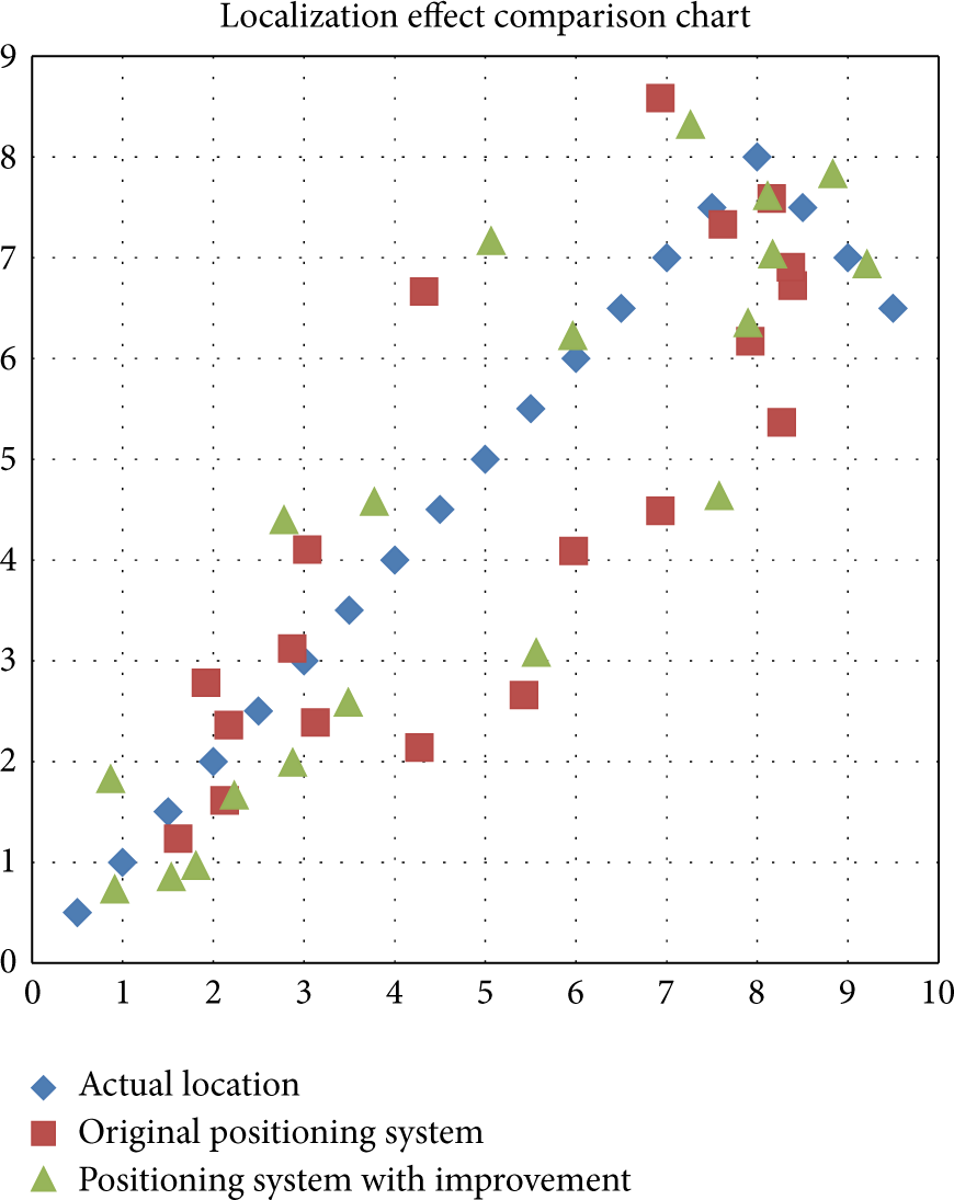
Localization comparison chart.
Experiment proves the improved positioning system can reduce error of steel pillars. The statistics of experiment are shown in Table 2.
System error comparison table.

6. Conclusion
According to the transmission characteristic of RSSI in the greenhouse, we proposed a positioning system based on RSSI partition in this paper. With the experiment data obtained from the greenhouse, two curves are fitted and two path-loss models are introduced to locate the blind node. Meanwhile a region segmentation mechanism is designed to improve the system performance. Experiments have shown that our system and algorithm have high positioning accuracy. It is appropriate to be applied in a complicated environment like the greenhouse.
Footnotes
Conflict of Interests
The author declares that there is no conflict of interests regarding the publication of this paper.
Acknowledgments
The work was financially supported by the National 863 High-Tech R&D Program of China (Grant no. 2012AA10A507 and no. 2013AA103006), the National Natural Science Foundation of China (Grant no. 61174090 and no. 61374094), and the Fundamental Research Funds for the Central Universities. The author hereby expresses many thanks.